US4900341A - Purification system - Google Patents
Purification system Download PDFInfo
- Publication number
- US4900341A US4900341A US07/213,235 US21323588A US4900341A US 4900341 A US4900341 A US 4900341A US 21323588 A US21323588 A US 21323588A US 4900341 A US4900341 A US 4900341A
- Authority
- US
- United States
- Prior art keywords
- container
- inlet
- purification system
- lower portion
- filter elements
- Prior art date
- Legal status (The legal status is an assumption and is not a legal conclusion. Google has not performed a legal analysis and makes no representation as to the accuracy of the status listed.)
- Expired - Fee Related
Links
Images
Classifications
-
- B—PERFORMING OPERATIONS; TRANSPORTING
- B08—CLEANING
- B08B—CLEANING IN GENERAL; PREVENTION OF FOULING IN GENERAL
- B08B15/00—Preventing escape of dirt or fumes from the area where they are produced; Collecting or removing dirt or fumes from that area
-
- A—HUMAN NECESSITIES
- A47—FURNITURE; DOMESTIC ARTICLES OR APPLIANCES; COFFEE MILLS; SPICE MILLS; SUCTION CLEANERS IN GENERAL
- A47J—KITCHEN EQUIPMENT; COFFEE MILLS; SPICE MILLS; APPARATUS FOR MAKING BEVERAGES
- A47J37/00—Baking; Roasting; Grilling; Frying
- A47J37/12—Deep fat fryers, e.g. for frying fish or chips
- A47J37/1214—Deep fat fryers, e.g. for frying fish or chips the food being transported through an oil-bath
-
- B—PERFORMING OPERATIONS; TRANSPORTING
- B01—PHYSICAL OR CHEMICAL PROCESSES OR APPARATUS IN GENERAL
- B01D—SEPARATION
- B01D47/00—Separating dispersed particles from gases, air or vapours by liquid as separating agent
- B01D47/14—Packed scrubbers
-
- B—PERFORMING OPERATIONS; TRANSPORTING
- B01—PHYSICAL OR CHEMICAL PROCESSES OR APPARATUS IN GENERAL
- B01D—SEPARATION
- B01D50/00—Combinations of methods or devices for separating particles from gases or vapours
- B01D50/60—Combinations of devices covered by groups B01D46/00 and B01D47/00
-
- F—MECHANICAL ENGINEERING; LIGHTING; HEATING; WEAPONS; BLASTING
- F24—HEATING; RANGES; VENTILATING
- F24C—DOMESTIC STOVES OR RANGES ; DETAILS OF DOMESTIC STOVES OR RANGES, OF GENERAL APPLICATION
- F24C15/00—Details
- F24C15/20—Removing cooking fumes
-
- Y—GENERAL TAGGING OF NEW TECHNOLOGICAL DEVELOPMENTS; GENERAL TAGGING OF CROSS-SECTIONAL TECHNOLOGIES SPANNING OVER SEVERAL SECTIONS OF THE IPC; TECHNICAL SUBJECTS COVERED BY FORMER USPC CROSS-REFERENCE ART COLLECTIONS [XRACs] AND DIGESTS
- Y10—TECHNICAL SUBJECTS COVERED BY FORMER USPC
- Y10S—TECHNICAL SUBJECTS COVERED BY FORMER USPC CROSS-REFERENCE ART COLLECTIONS [XRACs] AND DIGESTS
- Y10S55/00—Gas separation
- Y10S55/36—Kitchen hoods
Definitions
- the present invention relates to a fume purification system used in conjunction with food cooking equipment.
- Fume removal systems are widely used in commerical and residential environments.
- the use of a fan which expels a part of the fumes and a portion of the neighbouring air into the atmosphere is well known. In most instances, it is used in association with a canopy exhaust hood which captures the fumes from the cooking area and a filter which removes the particulate matter and sometimes a portion of the gases contained in the fumes.
- a canopy exhaust hood which captures the fumes from the cooking area and a filter which removes the particulate matter and sometimes a portion of the gases contained in the fumes.
- filters get rapidly clogged up with the resulting loss of filtering efficiency.
- U.S. Pat. No. 4,036,994 describes a method for reducing odor and smoke emissions by using an oxidizer such as hydrogen perioxide to scrub the fumes during their exit to the atmosphere.
- an oxidizer such as hydrogen perioxide to scrub the fumes during their exit to the atmosphere.
- this system is highly imperfect in that a significant portion of the fumes is still released in the atmosphere while the used water/scrubber is evacuated into the sewage system.
- U.S. Pat. No. 3,525,197 presents a purification system for removing dust from an air stream.
- the air stream enters in the system by a duct directed downwardly and then the largest air flow particles are collected in a container in the bottom of the system.
- the air is then passed through a plurality of hollow impingement elements. These elements are periodically washed by a liquid to remove the dust or other contaminants which may have adhered on them.
- U.S. Pat. No. 3,334,470 shows another dust removal system wherein a pair of nozzle means are provided for directing the gas into a high velocity stream. The nozzles converge towards each other, thus causing the liquid and gas in each stream to collide above the liquid bath, in which the contaminated liquid is collected.
- Another object of the present invention is to provide a purification system which removes grease, smoke or other particles from fumes.
- a further object of the present invention is to provide a purification which is easy to clean and particularly suitable for easy retrofitting of operating restaurants.
- Still another object of the present invention is to provide an effective closed-circuit purification system which is efficient, economical, easily installed and has low maintenance costs.
- a still further object of the present invention is to provide a fume purification system to be used in a fried food dispensing machine.
- a purification system in accordance with the present invention comprises a container having an oxidizing liquid bath in the bottom of said container, a plurality of balls placed inside the upper portion of said container, inlet and an outlet means connected to the hood of the cooking surface and a blower to suck the fumes away from the cooking surface.
- FIG. 1 is a side view of one embodiment of the present invention.
- FIG. 2 is a side view of the hood of the present invention mounted over a fired food dispensing machine so as to form a closed circuit purification system.
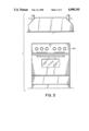
- FIG. 3 is a side view of the hook of the present invention mounted over a conventional stove.
- the purification system shown in FIG. 1 is more particularly adapted for use in a self-contained fried food dispensing machine.
- the typical food items which are prepared in such machines are french fries, onion rings, chicken or fish nuggets, etc.
- fumes generated during cooking of food products in the hot oil bath are collected, purified, cooled and recirculated. Since the food products handled here all have very high percentage of water content (over 90%) the largest constituent of the exhaust fumes is water vapour and steam. Other components of the emission fumes are a family of noncondensible gases which result from the high temperature exposure and the gradual degradation of the cooking oil and of the animal fats contained in the products used. There is also a certain amount of particulate matter and gasified oil/fat residues present in this blend of gases.
- FIG. 2 Gases produced during cooking and oil heating are collected and confined in a fully enclosed hoos 1 which is mounted right over the frying assembly generally referred to as 200 in FIG. 2 and 300 in FIG. 3.
- the frying assembly of FIG. 2 comprises a rotating basket 50 wherein the food to be cooked is placed. Said rotating backet is immersed in an oil bath 40 for the cooking.
- An exhaust port 2 is located on one side of the hood where the gas generation is concentrated. From here the gases are sucked into the condenser unit 3 where most of the gas purification and conditioning takes place.
- a blower 4 includes suction to extract the partially processed gases from exit port 5 of the condenser, and pushes it through the filter cartridge 6 for complete cleaning before re-entering into the hood at inlet port 7.
- Condenser 3 itself is fabricated from a double walled 8, cylindrical container which is equipped with a double wall cover 9. On the outside surface of the inside shell 8a, a copper tube coil 10 is wound and soldered (for better conductivity) to provide controlled cooling. Inside the condenser a large number of solid glass balls 11 having a predetermined diameter (for example, 1/2") are packed and supported on a circular wire mesh 12. The bottom part of the condenser is filled with a 21/2 percent potassium permanganate and water solution 13 up to the level of an overflow "T" 14. This solution is being circulated continuously in a closed circuit loop by a pump 15 at a rate of about 5 GPM through the entire glass ball packing.
- a pump 15 at a rate of about 5 GPM through the entire glass ball packing.
- a spray head 16 is provided fro even distribution of the solution 13. It consists of a centrally located hollow hub and four symmetrically arranged lateral, tubular branches 17. Holes 18 are drilled horizontally on these branches to create numerous, calibrated spray nozzles. These nozzles 18 are made to create a perfectly optimal distribution of solution. In practice it has been found to be very effective to direct about 2/3 of the circulated flow through the glass balls and 1/3 against the chilled, vertical inside wall 8a of the cylinder. This way a uniform capillary coating on the glass balls is attained for efficient scrubbing of the counter-flowing gases. At the same time the solution flowing down on the walls, is chilled to absorb the heat picked up from the hot emissive gases.
- the circular plate 20 mounted on the mesh support has a dual function. It deflects the incoming gas stream laterally for even distribution at the bottom line of the ball packing, and it also prevents the cascading solution to fall into the inlet opening 19.
- the dry and partially reconditioned gases enter into the tubular charcoal cartridge 6.
- a compacted bed of activated charcoal 22 is disposed between two wire mesh partitions 23a and 23b.
- the well established absorbtion technology of activated charcoal completes the removal of any remaining odor and gas constituents of the gases before re-directing the remaining portion (air) into the hooded enclosure 1 via inlet 7.
- a certain percentage of this purified air is expelled through a calibrated orifice 24 which is located on the exit side of the cartridge. This is provided to ensure a partial vacuum inside the enclosure 1 over the cooking zone.
- the objective of this provision is to prevent unpurified gases from leaking through any loose sealing of doors and/or bolted connections.
- the overflow "T" fitting 14 in installed to control the quantity of solution residing inside the condenser 3. This provision is necessary because the water content of the emissive gases is continuously added to the solution by condensation. Another function of this feature is to dispose of the layer of fat/oil precipitated in the scrubbing process. This way, therefore, the surplus solution and fatty slime is disposed into the water tank 25 via piping and a check valve 26. One directional operation of this valve prevents air from entering from the tank 25 into the condenser 3 which is under negative pressure.
- a cap 27 functions similarly to plate 20 to prevent drops of the cascading solution from entering into the overflow opening of "t" fitting 14.
- cover 9 be easily removable to allow access to the interior of the cylinder to clean or repair it.
Abstract
Description
Claims (16)
Applications Claiming Priority (2)
| Application Number | Priority Date | Filing Date | Title |
|---|---|---|---|
| CA541061 | 1987-06-30 | ||
| CA000541061A CA1292941C (en) | 1987-06-30 | 1987-06-30 | Purification system |
Publications (1)
| Publication Number | Publication Date |
|---|---|
| US4900341A true US4900341A (en) | 1990-02-13 |
Family
ID=4136013
Family Applications (1)
| Application Number | Title | Priority Date | Filing Date |
|---|---|---|---|
| US07/213,235 Expired - Fee Related US4900341A (en) | 1987-06-30 | 1988-06-29 | Purification system |
Country Status (6)
| Country | Link |
|---|---|
| US (1) | US4900341A (en) |
| EP (1) | EP0298000A3 (en) |
| JP (1) | JPS6434421A (en) |
| KR (1) | KR890000171A (en) |
| CN (1) | CN1030177A (en) |
| CA (1) | CA1292941C (en) |
Cited By (18)
| Publication number | Priority date | Publication date | Assignee | Title |
|---|---|---|---|---|
| WO1993018348A1 (en) * | 1992-03-05 | 1993-09-16 | Lucien Fauteux | Fume purification system |
| US5316569A (en) * | 1993-07-27 | 1994-05-31 | Heunermund Frederick W | Device for filtering sewer gases |
| US5358540A (en) * | 1993-12-22 | 1994-10-25 | Tsan Yun Chang | Exhaust cleaner for filter hoods |
| US5426953A (en) * | 1993-02-05 | 1995-06-27 | Meckler; Milton | Co-sorption air dehumidifying and pollutant removal system |
| US5472342A (en) * | 1993-12-27 | 1995-12-05 | Ldi, Mfg. Co., Inc. | Kitchen exhaust hood grease extractor |
| US5671726A (en) * | 1995-06-20 | 1997-09-30 | Hsu; Robert Y. | Cooking fume purifier |
| US6010558A (en) * | 1998-08-13 | 2000-01-04 | Flame Gard, Inc. | Grease containment system and method for absorbing grease |
| US6511844B1 (en) | 2000-02-11 | 2003-01-28 | Michael A. Smith | Air purification system and method of using the same |
| US6516711B1 (en) * | 1999-10-29 | 2003-02-11 | Patatas Chef, S.L. | Semiautomatic deep frier with fume and smell purifiers |
| US6698419B2 (en) * | 2000-09-26 | 2004-03-02 | Mong-yu Lee | Smoke extracting ventilation system for cooking |
| US20040139858A1 (en) * | 2001-03-01 | 2004-07-22 | Phillips Plastics Corporation | Filtration media of porous inorganic particles |
| US6797041B2 (en) | 2002-03-01 | 2004-09-28 | Greenheck Fan Corporation | Two stage air filter |
| US6814783B2 (en) | 2001-03-01 | 2004-11-09 | Phillips Plastics Corporation | Filtration media of porous inorganic particles |
| US20050028498A1 (en) * | 2003-08-04 | 2005-02-10 | Phillips Plastics Corporation | Separation apparatus |
| US20050087069A1 (en) * | 2003-10-22 | 2005-04-28 | Phillips Plastics Corporation | High capture efficiency baffle |
| US20100242737A1 (en) * | 2009-03-31 | 2010-09-30 | Liu Chun-Chi | Environmental protection double layer oil smoke filter device for kitchen range |
| US20150128816A1 (en) * | 2013-11-06 | 2015-05-14 | Lucien Fauteux | Automated self-contained cooking assembly |
| US10195470B2 (en) | 2013-03-15 | 2019-02-05 | Oy Halton Group Ltd. | Water spray fume cleansing with demand-based operation |
Families Citing this family (19)
| Publication number | Priority date | Publication date | Assignee | Title |
|---|---|---|---|---|
| CA1302103C (en) * | 1987-10-21 | 1992-06-02 | Julius S. Csabai | Revolving basket |
| US5272961A (en) * | 1988-10-17 | 1993-12-28 | The R/M Trust Company | Apparatus for providing french fried potatoes |
| US5180405A (en) * | 1992-06-09 | 1993-01-19 | Chi Chang Enterprises Co., Ltd. | Oily smoke purifying apparatus of central processing system type |
| IT1256899B (en) * | 1992-07-27 | 1995-12-27 | Massimo Bertotti | DEVICE FOR PURIFYING AND DEODORING FUMES, IN PARTICULAR FUMES GENERATED BY OVENS FOR DENTAL AND TECHNICAL USE, GOLDSMITH AND SIMILAR. |
| IT1289390B1 (en) * | 1996-08-05 | 1998-10-02 | Electrolux Zanussi Grandi Impi | METHOD AND DEVICE FOR THE PURIFICATION OF FLUIDS |
| DK199800249U3 (en) * | 1998-07-01 | 1998-11-27 | Fki Fast Food Teknik As | Belt grill with air purification system |
| FR2828414B1 (en) * | 2001-08-08 | 2003-11-14 | Patent Invest Group Holding Sa | GAS FLOW DEGREASER DEVICE |
| US7092077B2 (en) | 2001-09-24 | 2006-08-15 | Entegris, Inc. | System and method for monitoring contamination |
| US6620630B2 (en) * | 2001-09-24 | 2003-09-16 | Extraction Systems, Inc. | System and method for determining and controlling contamination |
| DE10235603A1 (en) * | 2002-08-02 | 2004-02-19 | Bernd Beck | Doner grill with filter system |
| JP4541668B2 (en) * | 2003-07-10 | 2010-09-08 | 株式会社コロナ | Gas processing equipment |
| ITFI20060006U1 (en) * | 2006-02-07 | 2007-08-08 | Target Catering Equipment S R L | DEVICE FOR FILLING SMOKES AND SMELLS FROM GASEOUS DISCHARGES FROM INDUSTRIAL KITCHENS |
| JP2011005483A (en) * | 2009-05-22 | 2011-01-13 | Kitagawa Elaborate Mach Co Ltd | Impurity recovery apparatus |
| GB2519541B (en) * | 2013-10-23 | 2017-05-24 | Reco-Air Ltd | Ventilation System |
| CN104957963B (en) * | 2015-06-10 | 2017-04-19 | 哈尔滨工业大学 | Aerospace specific food cooking and kitchen smoke purifying system |
| CN104957964B (en) * | 2015-06-10 | 2016-12-07 | 哈尔滨工业大学 | A kind of spacefarer's special Chinese style food prepares intelligence control system and food making method thereof |
| NL2015109B1 (en) * | 2015-07-07 | 2017-02-01 | Caenator B V | French fries vending machine. |
| CN112413668A (en) * | 2019-08-23 | 2021-02-26 | 金百利科技(深圳)有限公司 | Zero-emission type air conditioner oil fume purifier |
| CN111939688B (en) * | 2020-08-14 | 2021-12-07 | 浙江独山能源有限公司 | PTA refining condensate recovery device |
Citations (10)
| Publication number | Priority date | Publication date | Assignee | Title |
|---|---|---|---|---|
| US901010A (en) * | 1907-12-31 | 1908-10-13 | Fred Davis Jacobs | Car-ventilating system. |
| US1047534A (en) * | 1909-11-24 | 1912-12-17 | Edward Lionel Joseph | Apparatus for effecting the sterilization of water by ozonation. |
| US3005679A (en) * | 1960-10-24 | 1961-10-24 | Felix L Yerzley | Gas-liquid contact method |
| US3302372A (en) * | 1964-04-17 | 1967-02-07 | Armour Agricult Chem | Gas scrubbing process and apparatus |
| US3334470A (en) * | 1965-11-10 | 1967-08-08 | Nat Dust Collector Corp | Method and apparatus for collecting contaminants from gases |
| US3525197A (en) * | 1967-03-13 | 1970-08-25 | Buell Eng Co | Separator apparatus |
| US3837269A (en) * | 1972-11-22 | 1974-09-24 | Elster S Inc | Effluent ventilation and cleaning apparatus |
| US4036994A (en) * | 1975-03-21 | 1977-07-19 | H.G.C. Construction & Equipment Company, Inc. | Method for abating odor and smoke emissions in the vapor exhaust from a meat broiling grill |
| US4251236A (en) * | 1977-11-17 | 1981-02-17 | Ciba-Geigy Corporation | Process for purifying the off-gases from industrial furnaces, especially from waste incineration plants |
| US4382807A (en) * | 1981-04-13 | 1983-05-10 | Century 21 Pollution Control, Inc. | Apparatus for separating foreign matter from a gas with a heat exchanger |
Family Cites Families (4)
| Publication number | Priority date | Publication date | Assignee | Title |
|---|---|---|---|---|
| US1848576A (en) * | 1932-03-08 | Self-contained air filtering and cooling apparatus | ||
| FR1364147A (en) * | 1963-05-10 | 1964-06-19 | Method and device for ventilating air polluted with fat rising from culinary appliances | |
| CH633726A5 (en) * | 1977-11-17 | 1982-12-31 | Ciba Geigy Ag | METHOD FOR REMOVING ACID POLLUTANTS AND HOVING SUBSTANCES FROM EXHAUST GASES FROM INDUSTRIAL OVENS, ESPECIALLY FROM WASTE COMBUSTION PLANTS, AND SLUDGE SEPARATORS FOR THE EXECUTION THEREOF. |
| JPS6058228A (en) * | 1983-09-09 | 1985-04-04 | Senichi Masuda | Air purifying apparatus |
-
1987
- 1987-06-30 CA CA000541061A patent/CA1292941C/en not_active Expired - Lifetime
-
1988
- 1988-06-23 KR KR1019880007575A patent/KR890000171A/en not_active Application Discontinuation
- 1988-06-28 EP EP88420226A patent/EP0298000A3/en not_active Withdrawn
- 1988-06-29 US US07/213,235 patent/US4900341A/en not_active Expired - Fee Related
- 1988-06-30 CN CN88103999A patent/CN1030177A/en active Pending
- 1988-06-30 JP JP63161103A patent/JPS6434421A/en active Pending
Patent Citations (10)
| Publication number | Priority date | Publication date | Assignee | Title |
|---|---|---|---|---|
| US901010A (en) * | 1907-12-31 | 1908-10-13 | Fred Davis Jacobs | Car-ventilating system. |
| US1047534A (en) * | 1909-11-24 | 1912-12-17 | Edward Lionel Joseph | Apparatus for effecting the sterilization of water by ozonation. |
| US3005679A (en) * | 1960-10-24 | 1961-10-24 | Felix L Yerzley | Gas-liquid contact method |
| US3302372A (en) * | 1964-04-17 | 1967-02-07 | Armour Agricult Chem | Gas scrubbing process and apparatus |
| US3334470A (en) * | 1965-11-10 | 1967-08-08 | Nat Dust Collector Corp | Method and apparatus for collecting contaminants from gases |
| US3525197A (en) * | 1967-03-13 | 1970-08-25 | Buell Eng Co | Separator apparatus |
| US3837269A (en) * | 1972-11-22 | 1974-09-24 | Elster S Inc | Effluent ventilation and cleaning apparatus |
| US4036994A (en) * | 1975-03-21 | 1977-07-19 | H.G.C. Construction & Equipment Company, Inc. | Method for abating odor and smoke emissions in the vapor exhaust from a meat broiling grill |
| US4251236A (en) * | 1977-11-17 | 1981-02-17 | Ciba-Geigy Corporation | Process for purifying the off-gases from industrial furnaces, especially from waste incineration plants |
| US4382807A (en) * | 1981-04-13 | 1983-05-10 | Century 21 Pollution Control, Inc. | Apparatus for separating foreign matter from a gas with a heat exchanger |
Cited By (27)
| Publication number | Priority date | Publication date | Assignee | Title |
|---|---|---|---|---|
| WO1993018348A1 (en) * | 1992-03-05 | 1993-09-16 | Lucien Fauteux | Fume purification system |
| US5426953A (en) * | 1993-02-05 | 1995-06-27 | Meckler; Milton | Co-sorption air dehumidifying and pollutant removal system |
| US5316569A (en) * | 1993-07-27 | 1994-05-31 | Heunermund Frederick W | Device for filtering sewer gases |
| US5358540A (en) * | 1993-12-22 | 1994-10-25 | Tsan Yun Chang | Exhaust cleaner for filter hoods |
| US5472342A (en) * | 1993-12-27 | 1995-12-05 | Ldi, Mfg. Co., Inc. | Kitchen exhaust hood grease extractor |
| US5671726A (en) * | 1995-06-20 | 1997-09-30 | Hsu; Robert Y. | Cooking fume purifier |
| US6010558A (en) * | 1998-08-13 | 2000-01-04 | Flame Gard, Inc. | Grease containment system and method for absorbing grease |
| US6516711B1 (en) * | 1999-10-29 | 2003-02-11 | Patatas Chef, S.L. | Semiautomatic deep frier with fume and smell purifiers |
| US6511844B1 (en) | 2000-02-11 | 2003-01-28 | Michael A. Smith | Air purification system and method of using the same |
| US6698419B2 (en) * | 2000-09-26 | 2004-03-02 | Mong-yu Lee | Smoke extracting ventilation system for cooking |
| US20040139858A1 (en) * | 2001-03-01 | 2004-07-22 | Phillips Plastics Corporation | Filtration media of porous inorganic particles |
| US7115160B2 (en) | 2001-03-01 | 2006-10-03 | Phillips Plastics Corporation | Filtration media |
| US7018449B2 (en) | 2001-03-01 | 2006-03-28 | Phillips Plastic Corporation | Filtration media |
| US6814783B2 (en) | 2001-03-01 | 2004-11-09 | Phillips Plastics Corporation | Filtration media of porous inorganic particles |
| US20050002833A1 (en) * | 2001-03-01 | 2005-01-06 | Phillips Plastics Corporation | Filtration media |
| US20050016376A1 (en) * | 2001-03-01 | 2005-01-27 | Phillips Plastics Corporation | Filtration media |
| US20040194623A1 (en) * | 2002-03-01 | 2004-10-07 | Brownell Kyle A. | Two stage air filter |
| US6994743B2 (en) | 2002-03-01 | 2006-02-07 | Greenheck Fan Corporation | Two stage air filter |
| US6797041B2 (en) | 2002-03-01 | 2004-09-28 | Greenheck Fan Corporation | Two stage air filter |
| US20050028498A1 (en) * | 2003-08-04 | 2005-02-10 | Phillips Plastics Corporation | Separation apparatus |
| US7041159B2 (en) | 2003-08-04 | 2006-05-09 | Phillips Plastics Corporation | Separation apparatus |
| US20050087069A1 (en) * | 2003-10-22 | 2005-04-28 | Phillips Plastics Corporation | High capture efficiency baffle |
| US7166140B2 (en) | 2003-10-22 | 2007-01-23 | Phillips Plastics Corporation | High capture efficiency baffle |
| US20100242737A1 (en) * | 2009-03-31 | 2010-09-30 | Liu Chun-Chi | Environmental protection double layer oil smoke filter device for kitchen range |
| US10195470B2 (en) | 2013-03-15 | 2019-02-05 | Oy Halton Group Ltd. | Water spray fume cleansing with demand-based operation |
| US20150128816A1 (en) * | 2013-11-06 | 2015-05-14 | Lucien Fauteux | Automated self-contained cooking assembly |
| US10058213B2 (en) * | 2013-11-06 | 2018-08-28 | Lucien Fauteux | Automated self-contained cooking assembly |
Also Published As
| Publication number | Publication date |
|---|---|
| KR890000171A (en) | 1989-03-13 |
| CA1292941C (en) | 1991-12-10 |
| JPS6434421A (en) | 1989-02-03 |
| CN1030177A (en) | 1989-01-11 |
| EP0298000A3 (en) | 1990-05-16 |
| EP0298000A2 (en) | 1989-01-04 |
Similar Documents
| Publication | Publication Date | Title |
|---|---|---|
| US4900341A (en) | Purification system | |
| US3865193A (en) | Air scrubber apparatus with grease removal means | |
| US5298043A (en) | Filter system for smoke or polluted air | |
| CA1110162A (en) | Control of range hood emissions | |
| JP3268229B2 (en) | Exhaust gas purification device | |
| US7731922B2 (en) | Apparatus and method for cleaning, neutralizing carbon monoxide and recirculating exhaust air in a confined environment | |
| DK2149756T3 (en) | Method of heat recovery from an extractor hood | |
| US4753218A (en) | Continuous water wash hood type ventilating system | |
| US5904751A (en) | Separation apparatus | |
| US3494108A (en) | Air cleaner | |
| JP4658271B2 (en) | Separation method, separation apparatus and cooking facility | |
| US4382807A (en) | Apparatus for separating foreign matter from a gas with a heat exchanger | |
| CN204730293U (en) | A kind of fume purifier of fume and smoke exhaust ventilator | |
| JPH05137934A (en) | Apparatus for treating soot | |
| JPH0123056Y2 (en) | ||
| WO1993018348A1 (en) | Fume purification system | |
| JPH11169300A (en) | Smokeless cooker | |
| US3796549A (en) | Air scrubber apparatus | |
| US4720291A (en) | Aero-hydraulic pollution control system | |
| JP3851234B2 (en) | Exhaust equipment | |
| US5935300A (en) | Separation Apparatus | |
| JP6812090B2 (en) | Heat exchanger spill collector | |
| EP0236281A1 (en) | Apparatus for cleaning air from gases through washing and cooling | |
| CN214581327U (en) | Intelligent cooker | |
| JPS58148318A (en) | Air curtain type transverse direction sucking and discharging device |
Legal Events
| Date | Code | Title | Description |
|---|---|---|---|
| AS | Assignment |
Owner name: METATRON INVESTMENTS INC., 715, HALPERN AVENUE, DO Free format text: ASSIGNMENT OF ASSIGNORS INTEREST.;ASSIGNOR:CSABAI, JULIUS S.;REEL/FRAME:004942/0726 Effective date: 19880819 Owner name: METATRON INVESTMENTS INC.,CANADA Free format text: ASSIGNMENT OF ASSIGNORS INTEREST;ASSIGNOR:CSABAI, JULIUS S.;REEL/FRAME:004942/0726 Effective date: 19880819 |
|
| AS | Assignment |
Owner name: AGENCE QUEBECOISE DE VALORISATION INDUSTRIELLE DE Free format text: ASSIGNMENT OF ASSIGNORS INTEREST.;ASSIGNOR:METATRON INVESTMENTS INC.;REEL/FRAME:005657/0475 Effective date: 19910320 |
|
| REMI | Maintenance fee reminder mailed | ||
| LAPS | Lapse for failure to pay maintenance fees | ||
| FP | Lapsed due to failure to pay maintenance fee |
Effective date: 19940213 |
|
| STCH | Information on status: patent discontinuation |
Free format text: PATENT EXPIRED DUE TO NONPAYMENT OF MAINTENANCE FEES UNDER 37 CFR 1.362 |