US4901160A - Electronic camera - Google Patents
Electronic camera Download PDFInfo
- Publication number
- US4901160A US4901160A US07/054,590 US5459087A US4901160A US 4901160 A US4901160 A US 4901160A US 5459087 A US5459087 A US 5459087A US 4901160 A US4901160 A US 4901160A
- Authority
- US
- United States
- Prior art keywords
- digital
- signal
- analog
- image signal
- image
- Prior art date
- Legal status (The legal status is an assumption and is not a legal conclusion. Google has not performed a legal analysis and makes no representation as to the accuracy of the status listed.)
- Expired - Lifetime
Links
Images


Classifications
-
- H—ELECTRICITY
- H04—ELECTRIC COMMUNICATION TECHNIQUE
- H04N—PICTORIAL COMMUNICATION, e.g. TELEVISION
- H04N5/00—Details of television systems
- H04N5/76—Television signal recording
- H04N5/765—Interface circuits between an apparatus for recording and another apparatus
- H04N5/77—Interface circuits between an apparatus for recording and another apparatus between a recording apparatus and a television camera
-
- Y—GENERAL TAGGING OF NEW TECHNOLOGICAL DEVELOPMENTS; GENERAL TAGGING OF CROSS-SECTIONAL TECHNOLOGIES SPANNING OVER SEVERAL SECTIONS OF THE IPC; TECHNICAL SUBJECTS COVERED BY FORMER USPC CROSS-REFERENCE ART COLLECTIONS [XRACs] AND DIGESTS
- Y10—TECHNICAL SUBJECTS COVERED BY FORMER USPC
- Y10S—TECHNICAL SUBJECTS COVERED BY FORMER USPC CROSS-REFERENCE ART COLLECTIONS [XRACs] AND DIGESTS
- Y10S358/00—Facsimile and static presentation processing
- Y10S358/906—Hand-held camera with recorder in a single unit
Definitions
- the present invention relates to an electronic camera, that is, a camera for electronically recording an optical image and, more particularly, to an electronic camera having a detachable recording section using a memory, such as a disk, as a recording means.
- a conventional electronic camera of this type consists of an image pickup section for converting an optical image into an electrical signal and a disk recording section for electronically or magnetically recording the electrical signal.
- an electronic camera of this type has a solid-state memory, instead of a disk recording section, as the recording means, in order to eliminate its drawbacks.
- an electronic camera having a disk recording section as the recording means has the following drawbacks:
- a predetermined time interval is required for a rise time of disk rotation when recording of an image is started, and a shutter release opportunity can be lost.
- the camera housing must be water- and dust-proofed due to the necessity of disk change, resulting in a high cost.
- an electronic camera using a solid-state memory as a recording means has the following drawbacks:
- a semiconductor memory requires power to maintain data of a recorded optical image, and it is difficult to reserve it permanently.
- an electronic camera has an image pickup section including an image pickup element and a solid-state memory for recording at least one-frame of image signals from the image pickup element, and an external recording section including a non solid state memory means are provided separately.
- the image pickup section and the external recording section are detachable.
- the invention is characterized by comprising a voice pickup means for obtaining voice data to be recorded on the solid-state memory.
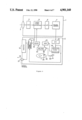
- FIG. 1 is a block diagram of a first embodiment of the present invention
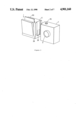
- FIG. 2 shows an outer appearance of the first embodiment
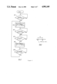
- FIG. 3(a) shows a flow chart and FIG. 3(b) shows a waveform chart of the operation of the first embodiment
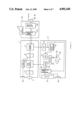
- FIG. 4 is a block diagram of a second embodiment of the present invention.
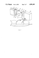
- FIG. 5 shows an outer appearance of the second embodiment
- FIG. 6 is a block diagram of a third embodiment of the present invention.
- FIG. 7 shows an outer appearance of the third embodiment.
- FIG. 1 is a block diagram of an arrangement of an electronic camera according to an embodiment of the present invention.
- the electronic camera of this embodiment basically comprises an image pickup section 1 and a disk recording section 2.
- the image pickup section 1 has a lens 3 and an image pickup element 4.
- the image pickup element 4 forms an optical image from the lens 3 and converts the optical image into an electrical signal, i.e., an image signal.
- the image pickup element 4 comprises a known image pickup means such as CCD, a MOS, an image pickup tube and so on.
- a signal processing curcuit 5 processes the image signal from the image pickup element.
- the image pickup section 1 also has an A/D converter 6 and a frame memory 7 for recording one-frame of digital image signals supplied from the A/D converter.
- the frame memory 7 can be field memory if needed.
- a nonvolatile DRAM is suitable as the frame memory 7. Therefore, a selection switch 8 is provided between the A/D converter 6 and the frame memory 7. When the frame memory 7 sequentially records incoming image signals, a contact a of the selection switch 8 is turned on. When a recording signal must be maintained, a contact b of the selection switch 8 is turned on. A recording signal is switched in this manner.
- a D/A converter 9 converts a digital image signal read out from the frame memory 7 into an analog signal.
- a monitor 10 displays an image signal as a visual image.
- a second selection switch 11 is also provided. When a contact a of the second selection switch 11 is turned on, raw image signals obtained by the image pickup element 4 and sequentially supplied via the signal processor 5 are supplied to the monitor 10 and displayed on it.
- the monitor 10 serves as a view finder of the camera.
- the image signal of the frame memory 7 is supplied to the monitor 10 via the D/A converter 9 and displayed on the monitor 10.
- a clock driver 12 supplies a clock pulses from a clock generator 13 to the image pickup element 4, the signal processing circuit 5, the A/D converter 9, the monitor 10, and so on.
- the respective units of the image pickup section 1 are driven in accordance with the clock pulse.
- a system controller 14 controls switching of the contacts of the selection switch 8 and the second selection switch 11 in accordance with the timing obtained by a release switch 15.
- the system controller 14 is also driven by a clock from the clock signal generator 13.
- a main switch 16 controls start/stop of the system controller.
- a power source 17 and a power source switch 18 are provided. Power from the power source 17 is supplied to the respective units of the image pickup section 1 and the disk recording section 2.
- the disk recording section 2 has a recording signal processing circuit 19.
- the recording signal processing circuit 19 performs signal processing in order to supply an analog signal, obtained by converting an image signal of the frame memory 7 by the D/A converter 9, to a recording disk to be described later.
- the disk recording section 2 has a recording disk 20.
- the recording disk 20 uses a magnetic sheet as the disk medium.
- Another medium such as an optical recording medium and a photomagnetic recording medium can also be used.
- An FM modulator 21 modulates an analog image signal from the D/A converter 9 into an FM signal and supplies the FM signal to the recording disk 20 when a recording disk is used as the magnetic medium.
- a recording/reproduction amplifier 22 is used to amplify the signal when the signal is to be recorded on the magnetic disk 20 or when a signal described later is reproduced.
- a digital image signal can be recorded without being converted into an analog signal by the D/A converter 9.
- a signal to be recorded does not pass the D/A converter 9 but is directly supplied to the disk recording section 2.
- the recording signal processing circuit 19 When a digital signal is directly recorded on the recording disk 20, the recording signal processing circuit 19 performs the signal processing necessary for processing a DC component in the signal. In this case, the FM modulator 21 can be omitted.
- the recording signal processing circuit 19 When a digital image signal is recorded, better image quality is obtained while the entire camera is simplified compared to the case wherein an analog image signal is recorded.
- a recording/reproduction head 23 is used to record and reproduce a signal on and from the recording disk 20.
- An FM demodulator 24 demodulates an FM reproduction signal supplied from the recording/reproduction amplifier 22.
- An analog image signal output from the FM demodulator 24 is supplied to the camera signal processing circuit 4 of the image pickup section 1. Therefore, the signal reproduced from the recording disk 20 can be displayed on the monitor 10 in the same manner as an image signal from the image pickup element 4.
- a microphone 32 and a voice processing circuit 33 are provided.
- the voice processing circuit 33 processes a voice signal from the microphone 32 by time base compression or the like.
- a loudspeaker 34 corrects a voice signal.
- a voice signal as well as an image signal can be recorded.
- a voice signal picked up by the microphone 32 is time-base compressed by the voice processing circuit 33 into a time-base compressed voice signal having the same frequency band as that of an image signal supplied from the image pickup element 4.
- a time-base compressed voice signal is short and has the same data amount as that of a longer voice signal. This signal is converted into a digital signal by the A/D converter 6 and recorded in the frame memory 7.
- the time-base compressed signal is then transferred onto the recording disk 20 in the same manner as for an image signal.
- a signal When a signal is reproduced, it is derived as a time-base compressed voice signal by the FM demodulator 24 in the same manner as an image signal, time-base expanded to a voice signal of a normal frequency band and having a normal time length by the reproduction signal processing circuit 31, and reproduced by the loudspeaker 34.
- the microphone 32 and the monitor 10 can be provided to one or both of the image pickup section 1 and the disk recording section 2.
- FIG. 2 shows an outer appearance of the electronic camera of the present invention.
- the same reference numerals are used to denote the same portions as in the block diagram of FIG. 1.
- a joint 25 includes a contact group 26 for electrically connecting the image pickup section 1 and the disk recording section 2.
- the electronic camera of the present invention operates in the following manner.
- step #1 the main switch 16 is turned on, and the system controller 14 is enabled.
- step #2 the power source switch 18 is turned on, and the contacts a of the selection switch 8 and the second selection switch 11 are turned on. In this step, power is supplied from the power source 17 to the respective portions to actuate them.
- the monitor 10 serves as the view finder of the camera.
- the system controller 14 generates a sync signal by a clock signal supplied from the clock generator 13.
- a vertical sync signal VD is generated every one frame period V, as shown in FIG. 3(b).
- the vertical sync signal VD is generated at a period of 1/2V.
- step #3 the flow advances to step #3 to turn on the release switch 15.
- the system controller 14 is driven and the vertical sync signal VD is supplied to the selection switch 8 and the second selection switch 11.
- the selection switch 8 and the second selection switch 11 are switched to their contacts b (step #5).
- the signal data on the frame memory 7 is connected through the contacts b, the image is fixed, and a so-called image freeze state is obtained.
- the frozen image is supplied to the monitor 10 through the contact b of the second selection switch 11 and displayed on it.
- the frozen image is also supplied to the disk recording section 2 through the D/A converter 9.
- the one-frame frozen image is recorded on the recording disk 20.
- step #6 When a next image is to be picked up, the release switch 15 is depressed again (step #6), and the flow returns to the state after step #1.
- the release switch 15 When the release switch 15 is turned on again, the operations as described above are sequentially performed, and the next image is recorded on the recording disk 20.
- the frame memory 7 has a small memory capacity of a limited frame number. However, if the memory capacity is greatly increased in the future, images of several tens of frames or more can be recorded.
- the electronic camera has a separate image pickup section 1 and a detachable disk recording section 2, as described above. After an image signal and a time-base compressed voice signal are temporarily stored in the frame memory 7, the image signal and the voice signal are transferred to the disk recording section 2. Therefore, a shutter release opportunity will not be lost due to a delay in the starting timing of the recording disk 20.
- the image pickup section 1 can be made small and lightweight. When peak power is decreased to decrease the power source load on the image pickup section 1, a signal is read out from the image pickup element 4 at a low speed and temporarily stored in the frame memory 7. Therefore, the number of photographing frames can be increased compared to a conventional electronic camera even with a cell of the same capacity.
- the image pickup section 1 is connected to the disk recording section 2, and the image and voice signals can be transferred from the frame memory 7 to the recording disk 20 at a normal speed.
- the content of the frame memory 7 can be reproduced and displayed on the monitor 10 through the D/A converter 9.
- the corresponding memory area of the recording disk 20 can store a new image.
- FIG. 4 shows a second embodiment of the present invention.
- the portions denoted with the same reference numerals as in FIG. 1 operate in the same manner as the first embodiment and a detailed description therefor is omitted.
- Some necessary circuits shown in detail in FIG. 1 are not shown in FIG. 4.
- an image pickup section 1 has the same arrangement and operation as those of the first embodiment.
- FIG. 5 shows an outer appearance of the second embodiment.
- an output terminal 27 for supplying an image signal to outside picks up an image signal displayed on the monitor 10 and displays it, through a cable 28, on a television monitor 29.
- a switch 30 controls the start of a recording/reproduction amplifier 22.
- the switch 30 is usd to determine whether an image in frame memory 7 of the image pickup section 1 is recorded on a disk 20. When the switch 30 is lightly depressed, a current image is not recorded on the disk 20 but a next image in the frame memory 7 is transferred. When the switch 30 is strongly depressed, a current image in the frame memory 7 is transferred, and both the frame memory 7 and the recording disk 20 can pick up and record a new image. The operation is shifted in this manner.
- the content of the frame memory 7 of the image pickup section can be automatically and sequentially transferred at once. In this case, it is easy to increase the number of recording frames of the frame memory 7 and to display these frames.
- the connection of the image pickup section 1 and the disk recording section 2 is not shown, they can be connected through a wire or without a wire.
- the monitor 10 is provided on the disk recording section 2.
- a reproduction signal processor 31 receives a reproduction signal from an FM demodulator 24, an image signal in the frame memory 7 supplied from D/A converter 9, and an input image signal supplied from an image pickup element 4 through a signal processor 5, and supplies them to the monitor 10 and the output terminal 27.
- the reproduction signal processor 31 also expands the time-base compressed voice signal on a time base, as described above.
- FIG. 6 is a block diagram of the embodiment shown in FIG. 3, and FIG. 7 shows an outer appearance of the same.
- the portions denoted by the same reference numerals are identical to those of other embodiments, and a detailed description therefor is omitted.
- a telephone set 35 is provided.
- a member 36 connects an image pickup section 1 and the telephone set 35.
- a contact group 37 performs electrical connection.
- Terminals 38 and 39 serve as interfaces with a receiver 40 of the telephone set and are connected to voice couplers 41 and 42 opposing the receiver 40.
- the telephone transmission section 35 has a data input/output terminal 43. Therefore, the frame memory 7 can be controlled through a transmission signal processing circuit 44, and data of an image signal in the frame memory 7 can be output.
- the terminal 43 can be a general microcomputer terminal and can be coupled to a microcomputer display, a printer, a disk memroy and so on with a known method.
- a voice signal from a microphone 32, an image signal from the image pickup element 4, and an image signal and a time-base compressed voice signal recorded in the frame memory 7 are modulated by a modulator/demodulator 45 through the transmission signal processing circuit 44, and converted into a carrier which is transmitted via a telephone line through the terminals 38 and 39.
- an image signal and a voice signal obtained and picked up at another timing are transmitted through the telephone line, they are input through the terminals 38 and 39, are demodulated by the modulator/demodulator 45 to have the base band, and reach the image pickup section 1 through the transmission signal processing circuit 44.
- the signals are transferred to the frame memory 7 and recorded and displayed in the same manner as described above.
- the image pickup section 1 and the telephone transmission section 35 are connected.
- the same effect can be obtained when a disk recording section 2 and the telephone transmission section 35 are connected.
- a solid-state memory performs data accessing for recording/reproduction in a non-mechanical manner and includes a magnetic bubble memory or the like.
- a non solid-state memory performs data accessing for recording/reproduction in a mechanical manner and includes a VTR or the like.
- a camera for picking up an optical image i.e., an image pickup section can be made small.
- the camera housing can easily be water- and dust-proofed.
- Photographing; reproduction, dubbing, and filing of an image or voice; and monitoring of the respective operation steps can be easily performed.
- the entire system can be easily extended for voice recording, telephone transmission, and data recording.
Abstract
Description
Claims (10)
Applications Claiming Priority (3)
| Application Number | Priority Date | Filing Date | Title |
|---|---|---|---|
| JP60201745A JPH0822043B2 (en) | 1985-09-13 | 1985-09-13 | Electronic camera |
| JP60-201745 | 1985-09-13 | ||
| PCT/JP1986/000479 WO1993013622A1 (en) | 1985-09-13 | 1986-09-13 | Electronic camera |
Publications (1)
| Publication Number | Publication Date |
|---|---|
| US4901160A true US4901160A (en) | 1990-02-13 |
Family
ID=26427124
Family Applications (1)
| Application Number | Title | Priority Date | Filing Date |
|---|---|---|---|
| US07/054,590 Expired - Lifetime US4901160A (en) | 1985-09-13 | 1986-09-13 | Electronic camera |
Country Status (1)
| Country | Link |
|---|---|
| US (1) | US4901160A (en) |
Cited By (20)
| Publication number | Priority date | Publication date | Assignee | Title |
|---|---|---|---|---|
| US5057925A (en) * | 1989-07-11 | 1991-10-15 | Ricoh Company, Ltd. | Still picture recorder utilizing a switch controlled timer |
| US5130813A (en) * | 1988-08-31 | 1992-07-14 | Casio Computer Co., Ltd. | Image data supervising system |
| DE4200875A1 (en) * | 1991-01-17 | 1992-07-23 | Samsung Electronics Co Ltd | VIDEO SIGNAL PLAYER WITH RECORDING FUNCTION AND RELATED PROCEDURE |
| US5170262A (en) * | 1985-09-13 | 1992-12-08 | Canon Kabushiki Kaisha | Electronic camera |
| US5337292A (en) * | 1989-08-16 | 1994-08-09 | Asahi Kogaku Kogyo Kabushiki Kaisha | Recording/reproducing apparatus with remote controller |
| US5376965A (en) * | 1989-09-14 | 1994-12-27 | Olympus Optical Co., Ltd. | Electronic imaging system capable of recording/reproducing images with any one of several possible recording media |
| EP0644690A2 (en) * | 1993-09-17 | 1995-03-22 | Lg Electronics Inc. | VCR with camcorder station apparatus |
| US5412425A (en) * | 1989-05-29 | 1995-05-02 | Canon Kabushiki Kaisha | Electronic still camera with power conservation facility |
| US5459582A (en) * | 1989-12-04 | 1995-10-17 | Canon Kabushiki Kaisha | Video signal processing system for taking into a memory a specified picture extracted from moving images |
| EP0729266A2 (en) * | 1995-02-21 | 1996-08-28 | Ricoh Company, Ltd | Digital electronic still camera |
| US5563655A (en) * | 1994-02-28 | 1996-10-08 | Eastman Kodak Company | Intelligent digital image storage for an electronic camera |
| EP0719036A3 (en) * | 1989-11-06 | 1996-12-27 | Canon Kk | Electronic still picture camera |
| US5726708A (en) * | 1987-10-29 | 1998-03-10 | Asahi Kogaku Kogyo Kabushiki Kaisha | Electronic still camera device |
| US5768163A (en) * | 1996-04-15 | 1998-06-16 | Hewlett-Packard | Versatile attachment of handheld devices to a host computing system |
| US5786851A (en) * | 1994-04-26 | 1998-07-28 | Canon Kabushiki Kaisha | Imaging system for recording or reproducing a photographed image signal or input audio signal as a digital signal |
| US5793444A (en) * | 1994-07-06 | 1998-08-11 | Lg Electronics Inc. | Audio and video signal recording and reproduction apparatus and method |
| US5815201A (en) * | 1995-02-21 | 1998-09-29 | Ricoh Company, Ltd. | Method and system for reading and assembling audio and image information for transfer out of a digital camera |
| US5821983A (en) * | 1994-05-20 | 1998-10-13 | Lucent Technologies, Inc. | Data message storage and transmission using a videophone and smart card |
| US6476869B1 (en) * | 1989-06-09 | 2002-11-05 | Canon Kabushiki Kaisha | Image processing system and method using system characteristic and image information |
| US20040201680A1 (en) * | 2001-05-30 | 2004-10-14 | Gennetten K. Douglas | Camera docking solution provides a user interface for printers, CD writers and other devices |
Citations (4)
| Publication number | Priority date | Publication date | Assignee | Title |
|---|---|---|---|---|
| JPS5744374A (en) * | 1980-08-29 | 1982-03-12 | Minolta Camera Co Ltd | Electrophotographic camera |
| JPS58182964A (en) * | 1982-04-21 | 1983-10-26 | Olympus Optical Co Ltd | Detachable unit type electrophotographing device |
| JPS58218004A (en) * | 1982-06-10 | 1983-12-19 | Fuji Photo Film Co Ltd | Sound recording system of electronic still camera |
| US4604668A (en) * | 1980-11-21 | 1986-08-05 | Lemelson Jerome H | Portable television camera and recording unit |
-
1986
- 1986-09-13 US US07/054,590 patent/US4901160A/en not_active Expired - Lifetime
Patent Citations (4)
| Publication number | Priority date | Publication date | Assignee | Title |
|---|---|---|---|---|
| JPS5744374A (en) * | 1980-08-29 | 1982-03-12 | Minolta Camera Co Ltd | Electrophotographic camera |
| US4604668A (en) * | 1980-11-21 | 1986-08-05 | Lemelson Jerome H | Portable television camera and recording unit |
| JPS58182964A (en) * | 1982-04-21 | 1983-10-26 | Olympus Optical Co Ltd | Detachable unit type electrophotographing device |
| JPS58218004A (en) * | 1982-06-10 | 1983-12-19 | Fuji Photo Film Co Ltd | Sound recording system of electronic still camera |
Non-Patent Citations (2)
| Title |
|---|
| Japanese article pp. 19 23, 11 15 83. * |
| Japanese article pp. 19-23, 11-15-83. |
Cited By (26)
| Publication number | Priority date | Publication date | Assignee | Title |
|---|---|---|---|---|
| US5170262A (en) * | 1985-09-13 | 1992-12-08 | Canon Kabushiki Kaisha | Electronic camera |
| US5726708A (en) * | 1987-10-29 | 1998-03-10 | Asahi Kogaku Kogyo Kabushiki Kaisha | Electronic still camera device |
| US5130813A (en) * | 1988-08-31 | 1992-07-14 | Casio Computer Co., Ltd. | Image data supervising system |
| US5412425A (en) * | 1989-05-29 | 1995-05-02 | Canon Kabushiki Kaisha | Electronic still camera with power conservation facility |
| US6476869B1 (en) * | 1989-06-09 | 2002-11-05 | Canon Kabushiki Kaisha | Image processing system and method using system characteristic and image information |
| US5057925A (en) * | 1989-07-11 | 1991-10-15 | Ricoh Company, Ltd. | Still picture recorder utilizing a switch controlled timer |
| US5475659A (en) * | 1989-08-16 | 1995-12-12 | Asahi Kogaku Kogyo Kabushiki Kaisha | Recording/reproducing apparatus |
| US5337292A (en) * | 1989-08-16 | 1994-08-09 | Asahi Kogaku Kogyo Kabushiki Kaisha | Recording/reproducing apparatus with remote controller |
| US5376965A (en) * | 1989-09-14 | 1994-12-27 | Olympus Optical Co., Ltd. | Electronic imaging system capable of recording/reproducing images with any one of several possible recording media |
| EP0719036A3 (en) * | 1989-11-06 | 1996-12-27 | Canon Kk | Electronic still picture camera |
| US5459582A (en) * | 1989-12-04 | 1995-10-17 | Canon Kabushiki Kaisha | Video signal processing system for taking into a memory a specified picture extracted from moving images |
| DE4200875A1 (en) * | 1991-01-17 | 1992-07-23 | Samsung Electronics Co Ltd | VIDEO SIGNAL PLAYER WITH RECORDING FUNCTION AND RELATED PROCEDURE |
| EP0644690A3 (en) * | 1993-09-17 | 1995-09-27 | Gold Star Co | VCR with camcorder station apparatus. |
| EP0644690A2 (en) * | 1993-09-17 | 1995-03-22 | Lg Electronics Inc. | VCR with camcorder station apparatus |
| US5563655A (en) * | 1994-02-28 | 1996-10-08 | Eastman Kodak Company | Intelligent digital image storage for an electronic camera |
| US5786851A (en) * | 1994-04-26 | 1998-07-28 | Canon Kabushiki Kaisha | Imaging system for recording or reproducing a photographed image signal or input audio signal as a digital signal |
| US5821983A (en) * | 1994-05-20 | 1998-10-13 | Lucent Technologies, Inc. | Data message storage and transmission using a videophone and smart card |
| US5793444A (en) * | 1994-07-06 | 1998-08-11 | Lg Electronics Inc. | Audio and video signal recording and reproduction apparatus and method |
| USRE39039E1 (en) * | 1994-07-06 | 2006-03-28 | Lg Electronics Inc. | Audio and video signal recording and reproduction apparatus and method |
| USRE43339E1 (en) | 1994-07-06 | 2012-05-01 | Lg Electronics Inc. | Audio and video signal recording and reproduction apparatus and method |
| US5815201A (en) * | 1995-02-21 | 1998-09-29 | Ricoh Company, Ltd. | Method and system for reading and assembling audio and image information for transfer out of a digital camera |
| EP0729266A3 (en) * | 1995-02-21 | 2000-07-05 | Ricoh Company, Ltd | Digital electronic still camera |
| EP0729266A2 (en) * | 1995-02-21 | 1996-08-28 | Ricoh Company, Ltd | Digital electronic still camera |
| US5768163A (en) * | 1996-04-15 | 1998-06-16 | Hewlett-Packard | Versatile attachment of handheld devices to a host computing system |
| US20040201680A1 (en) * | 2001-05-30 | 2004-10-14 | Gennetten K. Douglas | Camera docking solution provides a user interface for printers, CD writers and other devices |
| US7119835B2 (en) * | 2001-05-30 | 2006-10-10 | Hewlett-Packard Development Company, L.P. | Camera docking solution provides a user interface for printers, CD writers and other devices |
Similar Documents
| Publication | Publication Date | Title |
|---|---|---|
| US4901160A (en) | Electronic camera | |
| US5170262A (en) | Electronic camera | |
| US4897732A (en) | Electronic camera | |
| EP0617542B1 (en) | Recording and/or reproducing apparatus | |
| US5497194A (en) | Electronic camera for photographing and recording an image and for recording and reproducing a voice | |
| US5155584A (en) | Image recording reproducing apparatus switching image sensor signals or reproduced signals to an A/D converter | |
| US6618089B1 (en) | Display apparatus and electronic camera | |
| KR960010191B1 (en) | Still video camera | |
| JPH0822041B2 (en) | Electronic camera | |
| JP4200551B2 (en) | Imaging apparatus, image processing apparatus, imaging method, and image processing method | |
| US5740303A (en) | Magnetic recording system and method for a digital still video recorder | |
| JP2525385B2 (en) | Imaging device | |
| JPH0822042B2 (en) | Electronic camera | |
| US6999115B1 (en) | Image taking apparatus with an A/D converter and DSP with variable quantization bit numbers | |
| JPH0622262A (en) | Recorder | |
| JPH0822043B2 (en) | Electronic camera | |
| JPH07322195A (en) | Image recording/reproducing device and image/sound recording/reproducing device | |
| JPS63260376A (en) | Camera integrating type video tape recorder | |
| JP2692800B2 (en) | Data storage device | |
| EP1069781A3 (en) | Video signal recording and/or reproducing apparatus and methods, and image pickup apparatus | |
| KR100215308B1 (en) | Digital still camera using progressive ccd | |
| JPH01176167A (en) | Information signal recording system | |
| KR100247346B1 (en) | Apparatus for storing and reproducing data of pc using video cassette tape recorder | |
| JPH01277076A (en) | Electronic camera | |
| JPS63305684A (en) | Electronic camera |
Legal Events
| Date | Code | Title | Description |
|---|---|---|---|
| AS | Assignment |
Owner name: CANON KABUSHIKI KAISHA, 30-2, 3-CHOME, SHIMOMARUKO Free format text: ASSIGNMENT OF ASSIGNORS INTEREST.;ASSIGNORS:KINOSHITA, TAKAO;TAKISHIMA, YOSHIYUKI;REEL/FRAME:004727/0038 Effective date: 19870506 Owner name: CANON KABUSHIKI KAISHA, A CORP OF JAPAN,JAPAN Free format text: ASSIGNMENT OF ASSIGNORS INTEREST;ASSIGNORS:KINOSHITA, TAKAO;TAKISHIMA, YOSHIYUKI;REEL/FRAME:004727/0038 Effective date: 19870506 |
|
| STCF | Information on status: patent grant |
Free format text: PATENTED CASE |
|
| FEPP | Fee payment procedure |
Free format text: PAYOR NUMBER ASSIGNED (ORIGINAL EVENT CODE: ASPN); ENTITY STATUS OF PATENT OWNER: LARGE ENTITY |
|
| FPAY | Fee payment |
Year of fee payment: 4 |
|
| FPAY | Fee payment |
Year of fee payment: 8 |
|
| FEPP | Fee payment procedure |
Free format text: PAYER NUMBER DE-ASSIGNED (ORIGINAL EVENT CODE: RMPN); ENTITY STATUS OF PATENT OWNER: LARGE ENTITY |
|
| FPAY | Fee payment |
Year of fee payment: 12 |