US4901312A - Remote interconnection of local area networks - Google Patents
Remote interconnection of local area networks Download PDFInfo
- Publication number
- US4901312A US4901312A US07/241,846 US24184688A US4901312A US 4901312 A US4901312 A US 4901312A US 24184688 A US24184688 A US 24184688A US 4901312 A US4901312 A US 4901312A
- Authority
- US
- United States
- Prior art keywords
- bridge
- frame
- frames
- ring
- network
- Prior art date
- Legal status (The legal status is an assumption and is not a legal conclusion. Google has not performed a legal analysis and makes no representation as to the accuracy of the status listed.)
- Expired - Lifetime
Links
- 238000004891 communication Methods 0.000 claims abstract description 17
- 230000005540 biological transmission Effects 0.000 claims description 11
- 238000000034 method Methods 0.000 abstract description 11
- 238000010586 diagram Methods 0.000 description 9
- 238000012545 processing Methods 0.000 description 8
- 239000010410 layer Substances 0.000 description 7
- 230000007246 mechanism Effects 0.000 description 4
- 230000009471 action Effects 0.000 description 3
- 238000013507 mapping Methods 0.000 description 3
- 230000004044 response Effects 0.000 description 3
- 230000001360 synchronised effect Effects 0.000 description 3
- 238000009432 framing Methods 0.000 description 2
- FDSYTWVNUJTPMA-UHFFFAOYSA-N 2-[3,9-bis(carboxymethyl)-3,6,9,15-tetrazabicyclo[9.3.1]pentadeca-1(15),11,13-trien-6-yl]acetic acid Chemical compound C1N(CC(O)=O)CCN(CC(=O)O)CCN(CC(O)=O)CC2=CC=CC1=N2 FDSYTWVNUJTPMA-UHFFFAOYSA-N 0.000 description 1
- 241000271935 Bitis Species 0.000 description 1
- 230000000694 effects Effects 0.000 description 1
- 238000005538 encapsulation Methods 0.000 description 1
- 239000000284 extract Substances 0.000 description 1
- 229910000078 germane Inorganic materials 0.000 description 1
- 239000002346 layers by function Substances 0.000 description 1
- 238000012544 monitoring process Methods 0.000 description 1
- 230000008569 process Effects 0.000 description 1
- 238000011084 recovery Methods 0.000 description 1
- 230000000717 retained effect Effects 0.000 description 1
- 230000011664 signaling Effects 0.000 description 1
- 238000012546 transfer Methods 0.000 description 1
Images
Classifications
-
- H—ELECTRICITY
- H04—ELECTRIC COMMUNICATION TECHNIQUE
- H04L—TRANSMISSION OF DIGITAL INFORMATION, e.g. TELEGRAPHIC COMMUNICATION
- H04L12/00—Data switching networks
- H04L12/28—Data switching networks characterised by path configuration, e.g. LAN [Local Area Networks] or WAN [Wide Area Networks]
- H04L12/46—Interconnection of networks
- H04L12/4604—LAN interconnection over a backbone network, e.g. Internet, Frame Relay
- H04L12/462—LAN interconnection over a bridge based backbone
-
- H—ELECTRICITY
- H04—ELECTRIC COMMUNICATION TECHNIQUE
- H04L—TRANSMISSION OF DIGITAL INFORMATION, e.g. TELEGRAPHIC COMMUNICATION
- H04L2212/00—Encapsulation of packets
Definitions
- This invention relates to communication between Local Area Networks (LANs) and, particularly but not exclusively, between Token Rings (TRs) which are a particular type of LAN.
- LANs Local Area Networks
- TRs Token Rings
- a LAN is a digital communications network interconnecting several local computer workstations.
- Different types of LANs have been proposed including a serial loop configuration in which several adapters are arranged serially about the periphery of the loop with respective data sources connected to the adapters. In this configuration data flows from a data source through its associated source adapter and serially through one or more intervening adapters until it reaches the target adapter where it is extracted and forwarded to the target data source.
- a serial loop LAN is the Token Ring LAN developed by IBM.
- Token Ring LANs can be connected with one another using full bridges to form a multiple Token Ring LAN.
- interconnection by full bridges requires that the Token Rings be located physically proximate one another.
- a half-bridge To represent the network between the half-bridges, a half-bridge enters a number representing this pseudo ring in the Routing Information field of the frames it forwards over the network to a remote half-bridge.
- the communication network for interconnecting the remote LANs is referred generally hereinafter as a WAN (Wide Area Network).
- a WAN Wide Area Network
- a specific form of a WAN is a network containing some switching mechanism, to which the half-bridges are each interconnected by a single physical connection.
- Another form of a WAN is a simple point-to-point link for interconnection of only two remote LANs.
- WAN is used in this application to refer to the means for obtaining connectivity between the half-bridges, in the following senses.
- the WAN must provide a physical bi-directional channel to each half-bridge. The details of this channel and its interfaces can vary, as described elsewhere in this application with reference to the Adapter card used to interface to the WAN.
- the WAN may provide link-level bi-directional channels, commonly referred to as "logical links", between the half-bridges. These link-level channels are assumed to be nonduplicating and order-preserving, with possibly a small loss rate.
- Such a WAN provides in essence a mechanism for receiving link level frames from a physical channel attached to a half-bridge, switching these frames on the basis of their Data Link Connection Identifiers (DLCIs), and placing the switched frames on the physical channel attached to the destination half-bridge.
- DLCIs Data Link Connection Identifiers
- each half-bridge receives frames destined for a remote Token Ring from the local Token Ring, adjusts (if required) the proper Routing Information (RI) in the MAC (Medium Access Control) frame according to Token Ring Source Routing, envelopes the data in an LAPD frame with the proper Data Link Connection Identifier (DLCI) according to the destination, and sends the frame to the WAN.
- LAPD Link Access Protocol
- RI Routing Information
- MAC Medium Access Control
- the half-bridge receives LAPD frames from the WAN, extracts the MAC frame from the LAPD frame, adjusts the Routing Information (if required) and puts it on the Token Ring according to Token Ring protocol as described in the IBM Architecture Reference referred to above.
- the WAN is regarded as another Token Ring LAN by the half-bridges for the purpose of specifying Source Routing Information
- it is not a broadcast medium and so does not support switching by selective listening. Consequently, frames that are "All Rings Broadcast Frames" must be transmitted by a half-bridge on each of the logical links established with the remote half-bridges. Of course, frames destined for a specific ring are transmitted on only the one logical link that terminates on the appropriate remote half-bridge.
- the half-bridges of this invention must know the identity of the next bridge in the chain of bridges to the destination, as specified in the Routing Information. This knowledge enables the bridge to choose the appropriate logical link via a preconfigured mapping from bridge numbers to DLCIs. Consequently, the half-bridges must examine more of the Routing Information than do the conventional full bridges.
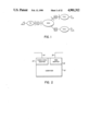
- FIG. 1 is a diagram illustrating the interconnection of several token ring networks by means of a Wide Area Network (WAN) according to the invention
- FIG. 2 is a diagram illustrating the hardware used for each of the bridges shown in FIG. 1;
- FIG. 3 is a diagram illustrating the bottom, functional layers of a LAN
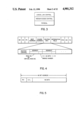
- FIG. 4 is a diagram illustrating the medium access control (MAC) frame format used
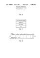
- FIG. 5 is a diagram illustrating how the Source Address field of the MAC frame of FIG. 4 is used to indicate the presence of a Route Information field;
- FIG. 6 is a diagram illustrating the format of the Routing Control field of the MAC frame of FIG. 4;
- FIG. 7 is a diagram illustrating how the MAC frame is encapsulated in a LAPD-compatible format by a bridge for transmission by the WAN of FIG. 1;
- FIG. 8 shows the various fields of the I-frame format used
- FIG. 9 is a diagram illustrating the format of the RR-frame format used.
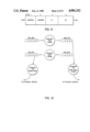
- FIG. 10 is a diagram illustrating the bridge functions
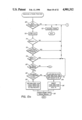
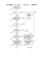
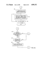
- FIGS. 11a-11c shows a flow chart illustrating the steps involved in processing a MAC frame from a Token Ring for transmission by the WAN;
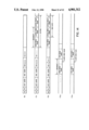
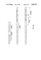
- FIGS. 12a and 12b illustrates the frame formats at different points of the flow chart of FIG. 11;
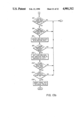
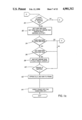
- FIGS. 13a and 13b shows a flow chart illustrating the steps involved in processing by a bridge a frame received from the WAN for distribution to a Token Ring;
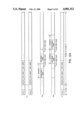
- FIG. 14 illustrates the frame formats at different points of the flow chart of FIG. 13.
- FIGS. 1 to 7 The invention will firstly be described in broad terms with reference to FIGS. 1 to 7 and will thereafter be described in more detail with reference to FIGS. 8 to 14 taken in conjunction with FIGS. 1 to 7.
- Each bridge can be seen to connect the respective Token Ring to the WAN. Although only one work station is shown connected to each Token Ring,in practice there could be two or more work stations connected to each Token Ring. Similarly, more than three Token Rings could be connected to the WAN, with each additional Token Ring having its own bridge.
- Each bridge is assigned a bridge number that is unique within the context of the Token Ring it is on, each Token Ring is assigned a unique ring number and the WAN is assigned a unique virtual or pseudo ring number.
- FIG. 2 illustrates the hardware used in an implementation of such a bridge.
- the main component is a computer 10 such as the Northern Telecom Vienna Advanced office computer (with associated hard disk, screen and keyboard) which is an IBM PC/AT compatible machine.
- the computer 10 is connected to its Token Ring via an IBM Token Ring Adapter Card II, indicated by reference numeral 12, and an IBM Token Ring Adapter cable 14 which connects to one of the ring's Multi-Station Access Units (not shown).
- IBM Token Ring Adapter 12 is described in the IBM manual entitled “IBM Token Ring Network PC Adapter: Guide to Operation” #67X0394 Second Edition June 1986 which is incorporated herein by reference.
- the interface between the computer 10 which runs the bridge software and the communication line 18 to the WAN is provided by a standard synchronous, serial card and its associated driver software.
- this card provides via a standard command/response interface, and is basically a means of translating between signals on the PC's bus and signals on the communication line that is plugged into the card.
- the ISDN PCTA card manufactured by Northern Telecom which provides an ISDNB-channel with HDLC framing. This card is described in full detail in the manuals supplied by Northern Telecom which manuals are incorporated hereinby reference.
- Every station on a LAN consists of a hierarchy of functions, the bottom layers of which are shown in FIG. 3.
- the physical functional component that handles the electrical signalling on the physical medium.
- the functional component that controls the access to the physical medium, cooperating with the corresponding level in all other stations on the LAN to share themedium.
- This layer formats the data appropriately into "MAC frames" to assist in this function.
- the functional component that, building upon the capabilities of the lower layers, may form logicallinks between stations.
- the present invention is particularly concerned with the MAC layer. More specifically, it describes a method of conveying MAC frames between LANs that may be physically distant.
- FIG. 4 shows the format of a MAC frame.
- This format is identical to the format described in the above-mentioned IBM Architecture Reference.
- the Routing Information field is, as can be seen in FIG.4, further divided into a 2-octet Routing Control field and as many as m 2-octet Segment Number fields where m is limited by the length of one of the subfields within the Routing Control field.
- the Segment Number fields contain in sequence the numbers of the rings and bridges through which theframe has to pass in order to transfer information from a work station on aparticular TR through the WAN to a work station on a different TR.
- the first Segment (FIG. 4) on the left would have ring number R1 and Bridge number B1
- the second Segment would have ring number R0 followed by Bridge number B2
- the third Segment would have ring number R2 with no accompanying Bridge number.
- R1 and R2 are the ring numbers assigned to TR1 and TR2 respectively
- B1 and B2 are the bridge numbers assigned to bridges B1 and B2 respectively
- R0 is the pseudo ring number assigned to the WAN.
- the frame format of FIG. 4 includes SD (Start Delimiter), ED (End Delimiter) fields which are distinctive patterns that allow a bridge to determine where a MAC frame begins and ends.
- SD Start Delimiter
- ED End Delimiter
- the SD and ED fields are stripped by the Token Ring adapter 12 before the frame is passed to the computer 10.
- the MAC frame shown in FIG. 4 also includes a FCS (Frame Check Sequence) field for checking bit errors in the frame and an FS (Frame Status) field which indicates whether or not the frame was recognized and copied by any station on the Token Ring. Both of these fields are removed from the MAC frame by the Adapter 2 before the frame is passed to computer 10.
- FCS Full Check Sequence
- FS Full Status
- the Adapter 12 adds the SD, ED, FCS and FS field to the MAC frame received from computer 10 for placing the frame on a Token Ring.
- this shows the format of the Routing Control fieldof FIG. 4. It consists of 16 bits, the first bit, B in the Figure, when setto 1 indicating that the frame has to be sent to all TR's. It does not imply that the frame is destined for all work stations on all TR's. "r" represents two bits reserved for future standardization. They are zeroes and their values will be ignored by receiving bridges.
- the next five bits marked LTH indicate the total length of the Routing Information field including the Routing Control field in octets. As the Routing Information field is of variable length while all the other fields in the frame headerare of fixed length, the length indicator is needed so that the remainder of the frame can be parsed.
- the LTH field indicates to a bridge where to insert the ring and bridge numbers.
- this field is initialized to 2 by the transmitting station. It is incremented by 4 by the first bridge that forwards the frame because the first bridge places both the first segment number and the second segment number in the RI field. Successive bridges insert only one segment number and therefore increment by 2.
- the length of the RI field also furnishes a basis for comparison with a bridge's hop-counts, for it reflects the number of segments, that a frame has been on so far.
- the field indicates the length of the RI field, but remains unchanged as the frame traverses the network.
- This bit indicates to a bridge whether a frame is travellingfrom the originating station to the target or the other way around. Its useallows the list of segments in the RI field to appear in the same order forframes travelling in both directions along the route.
- this shows the use of the Routing Information Indicator the Source address field address, as indicating the presence of a RI field.
- this RI indicator (RII) is set to 1 by the transmitter ofa frame, it indicates that an RI field is included in the frame.
- the MAC frame format described above can only be transmitted by the WAN if the MAC frame is encapsulated in a frame suitable for transmission into the WAN.
- the frame format chosen is compatible with LAPD (Link Access Protocol D channel) format; specifically, Multiframe Mode I-frames and RR-frames. It is noted that only the LAPD frame format is followed and that no LAPD elements of procedure are retained.
- the frame format is shownin FIG. 7. It can be seen that the MAC frame of FIG. 4 (less the SD, ED, FCS and FS fields as indicated above) is encapsulated between the header and the Frame Check Sequence (FCS) field of the LAPD-compatible frame, with a spare byte between the header and the MAC frame. The spare byte canbe used for bridge to bridge communication, i.e., for network management purposes.
- FCS Frame Check Sequence
- LAPD-compatible frame format used here includes in the header a Data Link Connection Identifier (DLCI) and this is used in the present invention.
- DLCI Data Link Connection Identifier
- Computer 10 modifies the bare MAC frame and adds the LAPD header containing the DLCI,and the spare byte.
- Adapter 16 adds the FCS field which completes the LAPD encapsulation asshown in FIG. 7.
- Adapter 16 receives the LAPD frame strips/checks the FCS field and forwards the frame to computer 10.
- Computer 10 strips the LAPD header and spare byte and forwards the modified MAC frame to Adapter 12.
- Adapter 12 adds the SD, ED, FCS and FS fields before the frame is passed to the Token Ring.
- Steps (2) and (5) above refer generally to actions by the computer in processing the frames. This processing is detailed as follows.
- the forwarding decisions are the same as those for frames received from theToken Ring Network.
- the frames are then placed into the queue for transmission on the Token Ring.
- the Token Ring Adapter 12 provides for the MAC layer protocol handling and all the details associated with being a work stationon the Token Ring.
- the Adapter 12 handles the procedures for Token claiming, error monitoring etc. It provides a simplified interface to the applications on computer 10, whereby information is exchanged by means of commands and responses.
- Adapter 16 enables the bridge to access the WAN via the access loop 18 and provides for the transmission of the LAPD-compatible frames without the underlying elements of procedure. In effect, the Adapter 16 provides the capability of transmitting a packet supplied by the computer 10 using LAPD-compatible framing.
- the bridge is implemented as a user program running on computer 10. More specifically, it uses a PC Disk Operating System DOS3.20, which is fully described in IBM documents such as "IBM DOS Technical Reference” Document Number 6138536 which is incorporated herein by reference.
- the frame formats used are compatible with LAPD as currently defined for conveying information on the D-Channel of Integrated Services Digital Networks (ISDN) and described in detail in the document entitled: "Report on the Meeting held in Geneva from 3 to 14 November 1986 [Part C.6.1--Recommendations Q.920 and Q.921]" published by the International Telegraph and Telephone Consultative Committee and incorporated herein by reference.
- I-frames for encapsulating the Token-Ring MAC frames
- RR-frames issued periodically if there is no other data to send, in order to maintain contact with all known remote bridges.
- the format of I-frames is as shown in FIG. 8.
- the address Field consists of two octets containing a Data Link Connection Identifier (DLCI), a Command/Response (C/R) bit, and two Address Extension(EA) bits.
- DLCI Data Link Connection Identifier
- C/R Command/Response
- EA Address Extension
- the DLCI consists of 13 bits, 6 bits in the first octet of the Address Field and 7 bits in the second octet. Bit 8 of the first octet is the mostsignificant bit; bit 2 of the second octet is the least significant.
- Each half-bridge when it is configured, has a table assigning a unique (to it)DLCI to each of the remote bridges with which it can communicate.
- the first octet's EA bit is always set to 0; the second octet's EA bit is always set to 1.
- the C/R bit is always set to 0.
- Control Field consists of two octets. These are not described further in this application since their usage is not pertinent to this applicationand is, moreover, described fully in the document cited above.
- the Information field consists of the data the bridge chooses to send. Thisconsists of a spare byte for possible use in the future, followed by a Token-Ring MAC frame.
- FCS Frame Check Sequence
- the format of RR-frames is as shown in FIG. 9.
- the Address Field is as described above for I-frames.
- the bridge does not implement the elements of procedure normally associatedwith the corresponding LAPD frame formats. That is, it does not take any action to recover frames lost or damaged in transit through the WAN. Instead, it relies on the WAN to provide a data transport service that is non-duplicating and order preserving, and it relies on the Token-Ring end-stations to take any necessary recovery actions.
- each bridge serves to process MAC frames received from a TRA (Token Ring Adapter) and transmit them as MAC frames on to the TR as illustrated in the Bottom part of FIG. 10.
- TRA Token Ring Adapter
- the software for carrying out this processing and which is stored in computer 10 is illustrated in the form of flow charts, FIGS. 11 and 13.
- block 20 represents the receiving of the MAC frame.
- Block 22 the presence or absence of Routing Information is determined by the RII bit in the Source Address of the MAC (see FIG. 5).
- block 30 decides that the Length field is not equal to 2, i.e., greater than 2, the program steps to block 34 which decides whether the last Ring number in the Routing Information field is equal to the local Ring Number and the WAN Ring Number does not occur. If the answer is yes, the program steps to block 36 which inserts the local bridge number and the WAN Ring Number and increments the L-field by 2, thereby giving the frame format F3(FIG. 12).
- the frame format F2 or F3 then passes to block 38 and 40 which modify the frame by adding for each DLCI in the bridge configuration the DLCI and field. This is shown as frame format F5 in FIG. 12. This frame is then inserted into the transmit queue for frames destined for the WAN, referredto as Queue WAN Qtx. Block 42 simply checks that all DLCI's have been added.
- the program then steps to block 50 which determines if there are 2 more segments in the information field and, if so, the program moves to block 52 where the current bridge Number, the distant Ring Number and the next bridge Number are obtained from the Routing Information field.
- the current bridge Number obtained is compared with the local bridge Number and if they are the same, the program steps to block 56 where the distant Ring Number obtained is compared to the WAN Ring Number and, if they are the same, the program steps to block 58 which mapsthe next bridge Number obtained from the RI field (block 52) to the DLCI ina look up table. Mapping errors are checked in block 60 and in block 62 theDLCI is appended to the frame as shown in F7 (FIG. 12) and finally the frame is inserted into the Queue WAN Qtx in block 64.
- Negative decisions at any of blocks 44, 46, 50, 54, 56 or 60 result in the program stepping to block 48 which discards the frame.
- FIGS. 13 and 14 when a frame F7 as shown in FIG. 12 is receivedfrom the WAN it is processed by the software in the bridge, the first step being a decision in block 68 as to whether the DLCI present is the one unique to that bridge. If it is, the program steps to block 70 where the DLCI is stripped as represented at F8 in FIG. 14. If the unique DLCI is not recognized, the frame is discarded at block 72.
- Blocks 74, 76, 78, 80 and 82 correspond to blocks 22, 24, 26, 28 and 30 of FIG. 11.
- the LTH-Field does not equal 2 and the program steps to block 84 which decides whether the last Ring Number in the Routing Information field equals the WAN Ring Number and the Local Ring Number does not occur. If the answer is yes, the program steps to block 86 which inserts the Local Bridge and Ring Numbers into the Routing Information field as shown at F10 in FIG. 14.
- the program then steps to block 88 which inserts frame F10 into the transmit queue for frames destined for the local Token Ring, referred to as Queue TRA Qtx.
- the Adapter Card 12 adds the SD, ED, FCS and FS fields before the frame is passed to the Token Ring.
- Block 90 relates to the general case of where a WAN Ring Number is added tothe Routing Information field if the bridge is the first to forward and would not, of course, apply in the case of receiving frames from the WAN.
- the current bridge Number obtained is compared with the local bridge Number and, if they are the same, the program steps to block 104 where the destination Ring Number obtained is compared to the local Ring Number and, if they are the same, the program steps to block 106 which inserts frame F11a or F11b into the transmit queue.
Abstract
Description
Claims (7)
Applications Claiming Priority (2)
| Application Number | Priority Date | Filing Date | Title |
|---|---|---|---|
| CA000565962A CA1294347C (en) | 1988-05-05 | 1988-05-05 | Remote interconnection of local area networks |
| CA565962 | 1988-05-05 |
Publications (1)
| Publication Number | Publication Date |
|---|---|
| US4901312A true US4901312A (en) | 1990-02-13 |
Family
ID=4137969
Family Applications (1)
| Application Number | Title | Priority Date | Filing Date |
|---|---|---|---|
| US07/241,846 Expired - Lifetime US4901312A (en) | 1988-05-05 | 1988-09-08 | Remote interconnection of local area networks |
Country Status (2)
| Country | Link |
|---|---|
| US (1) | US4901312A (en) |
| CA (1) | CA1294347C (en) |
Cited By (50)
| Publication number | Priority date | Publication date | Assignee | Title |
|---|---|---|---|---|
| US5086426A (en) * | 1987-12-23 | 1992-02-04 | Hitachi, Ltd. | Communication network system having a plurality of different protocal LAN's |
| EP0511144A1 (en) * | 1991-04-18 | 1992-10-28 | International Business Machines Corporation | Method and apparatus for interconnection of local area networks with wide area networks |
| EP0518581A1 (en) * | 1991-06-14 | 1992-12-16 | Digital Equipment International Limited | Routing in communications networks |
| US5179555A (en) * | 1990-09-11 | 1993-01-12 | Microcom Systems, Inc. | High speed data compression and transmission for wide area network connections in LAN/bridging applications |
| US5214648A (en) * | 1989-06-30 | 1993-05-25 | French State Represented By The Minister Of The Post, Telecommunications And Space | Complementary communication system in the no-connection mode for asynchronous time-division network |
| US5251213A (en) * | 1992-05-12 | 1993-10-05 | Microcom Systems, Inc. | Multiport source routing token ring bridge apparatus |
| EP0567217A2 (en) * | 1992-04-20 | 1993-10-27 | 3Com Corporation | System of extending network resources to remote networks |
| US5327431A (en) * | 1989-07-19 | 1994-07-05 | Ncr Corporation | Method and apparatus for source routing bridging |
| US5351242A (en) * | 1992-04-14 | 1994-09-27 | Marian Kramarczyk | Method and apparatus for configuring and maintaining token ring networks |
| US5355365A (en) * | 1993-03-31 | 1994-10-11 | Multi-Tech Systems, Inc. | Intelligent local area network modem node |
| US5404491A (en) * | 1989-07-13 | 1995-04-04 | Alcatel N.V. | Subscriber module for connection to a plurality of subscriber terminals and to an integrated services digital communication network (ISDN) |
| US5421024A (en) * | 1991-04-30 | 1995-05-30 | Hewlett-Packard Company | Detection of a relative location of a network device using a multicast packet processed only by hubs |
| US5428615A (en) * | 1991-01-25 | 1995-06-27 | Digital Equipment Corp. | Many to few group address translation through a network bridge |
| US5430727A (en) * | 1990-09-04 | 1995-07-04 | Digital Equipment Corporation | Multiple protocol routing |
| US5430728A (en) * | 1992-12-10 | 1995-07-04 | Northern Telecom Limited | Single-route broadcast for LAN interconnection |
| US5432907A (en) * | 1992-05-12 | 1995-07-11 | Network Resources Corporation | Network hub with integrated bridge |
| US5434864A (en) * | 1991-01-25 | 1995-07-18 | Digital Equipment Corporation | Encapsulation of an address within a forwarded frame in a computer communications system |
| US5504747A (en) * | 1993-03-03 | 1996-04-02 | Apple Computer, Inc. | Economical payload stream routing in a multiple-ring network |
| US5535326A (en) * | 1992-07-31 | 1996-07-09 | International Business Machines Corporation | System and method for logical console verification and feedback |
| US5539727A (en) * | 1992-04-14 | 1996-07-23 | Kramarczyk; Marian | Method and apparatus for configuring and maintaining token ring networks |
| US5581558A (en) * | 1995-03-29 | 1996-12-03 | Lucent Technologies Inc. | Apparatus for bridging non-compatible network architectures |
| US5594732A (en) * | 1995-03-03 | 1997-01-14 | Intecom, Incorporated | Bridging and signalling subsystems and methods for private and hybrid communications systems including multimedia systems |
| US5594728A (en) * | 1994-01-26 | 1997-01-14 | International Business Machines Corporation | Realtime addressing for high speed serial bit stream |
| US5666359A (en) * | 1995-07-12 | 1997-09-09 | Compaq Computer Corp. | Method and apparatus for displaying port information |
| US5720032A (en) * | 1992-05-12 | 1998-02-17 | Compaq Computer Corporation | Network packet switch using shared memory for repeating and bridging packets at media rate |
| US5724356A (en) * | 1995-04-28 | 1998-03-03 | Multi-Tech Systems, Inc. | Advanced bridge/router local area network modem node |
| US5761425A (en) * | 1994-12-02 | 1998-06-02 | Compuserve Incorporated | System for facilitating data transfers between host computers and workstations by having a first, second and third computer programs communicate in a matching application-level protocol |
| US5761433A (en) * | 1995-11-13 | 1998-06-02 | Billings; Roger E. | System for communicating data in a network using both a daisy chain link and separate broadcast links |
| US5793981A (en) * | 1995-11-13 | 1998-08-11 | Billings; Roger E. | System for communicating data in a network using both a daisy chain link and separate broadcast links |
| US5796738A (en) * | 1995-03-13 | 1998-08-18 | Compaq Computer Corporation | Multiport repeater with collision detection and jam signal generation |
| US5802285A (en) * | 1992-05-29 | 1998-09-01 | Icl Personal Systems Oy | Wide area network (WAN) interface for a transmission control protocol/internet protocol (TCP/IP) in a local area network (LAN) |
| US5844902A (en) * | 1992-04-07 | 1998-12-01 | Cabletron Systems, Inc. | Assigning multiple parallel bridge numbers to bridges |
| US5845086A (en) * | 1994-09-29 | 1998-12-01 | Siemens Aktiengesellschaft | System for addressing a destination station using only address of a network junction and station link identifier in a network with plurality of segments |
| US5870386A (en) * | 1991-01-09 | 1999-02-09 | Digital Equipment Corporation | Method and apparatus for transparently bridging traffic across wide area networks |
| US5878043A (en) * | 1996-05-09 | 1999-03-02 | Northern Telecom Limited | ATM LAN emulation |
| US5931916A (en) * | 1994-12-09 | 1999-08-03 | British Telecommunications Public Limited Company | Method for retransmitting data packet to a destination host by selecting a next network address of the destination host cyclically from an address list |
| US5978881A (en) * | 1997-02-24 | 1999-11-02 | Sigma Electronics, Inc. | Scalable switcher with detachably securable frame adapter cards for routing audio and video signals |
| US6055601A (en) * | 1995-10-17 | 2000-04-25 | Casio Computer Co., Ltd. | Data receiving apparatus capable of writing only necessary data in a file at the time of data reception |
| US6061730A (en) * | 1995-11-13 | 2000-05-09 | Billings; Roger E. | Methods and apparatus for communicating data in computer networks with separate packet assembly and packet broadcast channels |
| US6076117A (en) * | 1995-11-13 | 2000-06-13 | Billings; Roger E. | Packet merging hub system for sequentially merging received data in a network hub into data packets before broadcasting to a plurality of destination computers |
| US6115747A (en) * | 1995-11-13 | 2000-09-05 | Roger E. Billings | Computer network interface that merges remote data received from other computers with local data before transmitting the merged data to a network |
| US6178171B1 (en) | 1997-11-24 | 2001-01-23 | International Business Machines Corporation | Route switching mechanisms for source-routed ATM networks |
| WO2001022679A2 (en) * | 1999-09-17 | 2001-03-29 | Telefonaktiebolaget Lm Ericsson (Publ) | Method and apparatus for multiplexing packet data flows |
| US20020015407A1 (en) * | 2000-04-12 | 2002-02-07 | Infineon Technologies, Ag | Method for transmitting information by means of data packets and network for transmitting data |
| US20030091028A1 (en) * | 1997-07-25 | 2003-05-15 | Chang Gordon K. | Apparatus and method for integrated voice gateway |
| US6567410B1 (en) | 1996-08-08 | 2003-05-20 | Enterasys Networks, Inc. | Assigning multiple parallel bridge numbers to bridges having three or more ports |
| US6584107B1 (en) * | 1997-01-22 | 2003-06-24 | Siemens Aktiengesellschaft | Method for realizing emulated ring network structures in a communication network that is designed according to asynchronous transfer mode |
| US6647428B1 (en) * | 2000-05-05 | 2003-11-11 | Luminous Networks, Inc. | Architecture for transport of multiple services in connectionless packet-based communication networks |
| US6775284B1 (en) | 2000-01-07 | 2004-08-10 | International Business Machines Corporation | Method and system for frame and protocol classification |
| US20070083907A1 (en) * | 2005-10-07 | 2007-04-12 | Sbc Knowledge Ventures L.P. | Delivery of broadcast TV over point-point routed GRE tunnels for IPTV applications |
Citations (5)
| Publication number | Priority date | Publication date | Assignee | Title |
|---|---|---|---|---|
| US4587651A (en) * | 1983-05-04 | 1986-05-06 | Cxc Corporation | Distributed variable bandwidth switch for voice, data, and image communications |
| GB2170079A (en) * | 1984-12-14 | 1986-07-23 | Vitalink Communications Corp | Method and apparatus for bridging local area networks |
| US4621362A (en) * | 1984-06-04 | 1986-11-04 | International Business Machines Corp. | Routing architecture for a multi-ring local area network |
| US4718060A (en) * | 1985-03-04 | 1988-01-05 | Nippon Telegraph & Telephone Corp. | Station arrangement in data transmission network |
| US4797881A (en) * | 1987-03-12 | 1989-01-10 | Sytek, Inc. | Bridge system for connecting networks |
-
1988
- 1988-05-05 CA CA000565962A patent/CA1294347C/en not_active Expired - Fee Related
- 1988-09-08 US US07/241,846 patent/US4901312A/en not_active Expired - Lifetime
Patent Citations (6)
| Publication number | Priority date | Publication date | Assignee | Title |
|---|---|---|---|---|
| US4587651A (en) * | 1983-05-04 | 1986-05-06 | Cxc Corporation | Distributed variable bandwidth switch for voice, data, and image communications |
| US4621362A (en) * | 1984-06-04 | 1986-11-04 | International Business Machines Corp. | Routing architecture for a multi-ring local area network |
| GB2170079A (en) * | 1984-12-14 | 1986-07-23 | Vitalink Communications Corp | Method and apparatus for bridging local area networks |
| US4706081A (en) * | 1984-12-14 | 1987-11-10 | Vitalink Communications Corporation | Method and apparatus for bridging local area networks |
| US4718060A (en) * | 1985-03-04 | 1988-01-05 | Nippon Telegraph & Telephone Corp. | Station arrangement in data transmission network |
| US4797881A (en) * | 1987-03-12 | 1989-01-10 | Sytek, Inc. | Bridge system for connecting networks |
Non-Patent Citations (10)
| Title |
|---|
| "An Architecture for Interconnecting Lan Segments", Jul. 30, 1984 by Messrs. Kian-Bon K. Sy, Daniel Avery Pitt and Robert A. Donnan. |
| "Gateways and Bridges for Local Area Networks" by David A. Cates. |
| "Report on the meeting held in Geneva from 3-14 Nov. 1986 [Part c.6.1-Recommendations Q.920 and Q.921]". |
| "Survey of Computer Communications Loop Network: Part 1", BK Penney and AA Baghdadi, Computer Communications, vol. 2, No. 4, Aug. 1979, pp. 165-180. |
| ADAX Manual "PC-SDMA Synchronous Serial Controller For IBM SNA/SDLC, 3270, and CCITT/HDLC Data Communications", Jun. 1986. |
| ADAX Manual PC SDMA Synchronous Serial Controller For IBM SNA/SDLC, 3270, and CCITT/HDLC Data Communications , Jun. 1986. * |
| An Architecture for Interconnecting Lan Segments , Jul. 30, 1984 by Messrs. Kian Bon K. Sy, Daniel Avery Pitt and Robert A. Donnan. * |
| Gateways and Bridges for Local Area Networks by David A. Cates. * |
| Report on the meeting held in Geneva from 3 14 Nov. 1986 Part c.6.1 Recommendations Q.920 and Q.921 . * |
| Survey of Computer Communications Loop Network: Part 1 , BK Penney and AA Baghdadi, Computer Communications, vol. 2, No. 4, Aug. 1979, pp. 165 180. * |
Cited By (71)
| Publication number | Priority date | Publication date | Assignee | Title |
|---|---|---|---|---|
| US5086426A (en) * | 1987-12-23 | 1992-02-04 | Hitachi, Ltd. | Communication network system having a plurality of different protocal LAN's |
| US5214648A (en) * | 1989-06-30 | 1993-05-25 | French State Represented By The Minister Of The Post, Telecommunications And Space | Complementary communication system in the no-connection mode for asynchronous time-division network |
| US5404491A (en) * | 1989-07-13 | 1995-04-04 | Alcatel N.V. | Subscriber module for connection to a plurality of subscriber terminals and to an integrated services digital communication network (ISDN) |
| US5327431A (en) * | 1989-07-19 | 1994-07-05 | Ncr Corporation | Method and apparatus for source routing bridging |
| US5430727A (en) * | 1990-09-04 | 1995-07-04 | Digital Equipment Corporation | Multiple protocol routing |
| US5179555A (en) * | 1990-09-11 | 1993-01-12 | Microcom Systems, Inc. | High speed data compression and transmission for wide area network connections in LAN/bridging applications |
| US5870386A (en) * | 1991-01-09 | 1999-02-09 | Digital Equipment Corporation | Method and apparatus for transparently bridging traffic across wide area networks |
| US6445710B1 (en) | 1991-01-09 | 2002-09-03 | Enterasys Networks, Inc. | Method and apparatus for transparently bridging traffic across wide area networks |
| US5434864A (en) * | 1991-01-25 | 1995-07-18 | Digital Equipment Corporation | Encapsulation of an address within a forwarded frame in a computer communications system |
| US5450407A (en) * | 1991-01-25 | 1995-09-12 | Digital Equipment Corp. | Encapsulation of an address within a forwarded frame in a computer communications system |
| US5956335A (en) * | 1991-01-25 | 1999-09-21 | Cabletron Systems, Inc. | Many to few group address translation through a network bridge |
| US5428615A (en) * | 1991-01-25 | 1995-06-27 | Digital Equipment Corp. | Many to few group address translation through a network bridge |
| JPH05102970A (en) * | 1991-04-18 | 1993-04-23 | Internatl Business Mach Corp <Ibm> | Method and apparatus for connecting local network to large-area network |
| JPH0810875B2 (en) | 1991-04-18 | 1996-01-31 | インターナショナル・ビジネス・マシーンズ・コーポレイション | Method and apparatus for connecting a local network with a global network |
| US6463064B1 (en) | 1991-04-18 | 2002-10-08 | International Business Machines Corporation | Method and apparatus interconnection of local area networks with wide area networks |
| EP0511144A1 (en) * | 1991-04-18 | 1992-10-28 | International Business Machines Corporation | Method and apparatus for interconnection of local area networks with wide area networks |
| US5421024A (en) * | 1991-04-30 | 1995-05-30 | Hewlett-Packard Company | Detection of a relative location of a network device using a multicast packet processed only by hubs |
| US5491692A (en) * | 1991-06-14 | 1996-02-13 | Digital Equipment International Limited | Hybrid units for a communication network |
| EP0518581A1 (en) * | 1991-06-14 | 1992-12-16 | Digital Equipment International Limited | Routing in communications networks |
| US5844902A (en) * | 1992-04-07 | 1998-12-01 | Cabletron Systems, Inc. | Assigning multiple parallel bridge numbers to bridges |
| US5351242A (en) * | 1992-04-14 | 1994-09-27 | Marian Kramarczyk | Method and apparatus for configuring and maintaining token ring networks |
| US5539727A (en) * | 1992-04-14 | 1996-07-23 | Kramarczyk; Marian | Method and apparatus for configuring and maintaining token ring networks |
| EP0567217A3 (en) * | 1992-04-20 | 1998-09-09 | 3Com Corporation | System of extending network resources to remote networks |
| US5423002A (en) * | 1992-04-20 | 1995-06-06 | 3Com Corporation | System for extending network resources to remote networks |
| US5583997A (en) * | 1992-04-20 | 1996-12-10 | 3Com Corporation | System for extending network resources to remote networks |
| EP0567217A2 (en) * | 1992-04-20 | 1993-10-27 | 3Com Corporation | System of extending network resources to remote networks |
| US5737525A (en) * | 1992-05-12 | 1998-04-07 | Compaq Computer Corporation | Network packet switch using shared memory for repeating and bridging packets at media rate |
| US5432907A (en) * | 1992-05-12 | 1995-07-11 | Network Resources Corporation | Network hub with integrated bridge |
| US5742760A (en) * | 1992-05-12 | 1998-04-21 | Compaq Computer Corporation | Network packet switch using shared memory for repeating and bridging packets at media rate |
| US5251213A (en) * | 1992-05-12 | 1993-10-05 | Microcom Systems, Inc. | Multiport source routing token ring bridge apparatus |
| US5720032A (en) * | 1992-05-12 | 1998-02-17 | Compaq Computer Corporation | Network packet switch using shared memory for repeating and bridging packets at media rate |
| US5802285A (en) * | 1992-05-29 | 1998-09-01 | Icl Personal Systems Oy | Wide area network (WAN) interface for a transmission control protocol/internet protocol (TCP/IP) in a local area network (LAN) |
| US5535326A (en) * | 1992-07-31 | 1996-07-09 | International Business Machines Corporation | System and method for logical console verification and feedback |
| US5430728A (en) * | 1992-12-10 | 1995-07-04 | Northern Telecom Limited | Single-route broadcast for LAN interconnection |
| US5504747A (en) * | 1993-03-03 | 1996-04-02 | Apple Computer, Inc. | Economical payload stream routing in a multiple-ring network |
| US5355365A (en) * | 1993-03-31 | 1994-10-11 | Multi-Tech Systems, Inc. | Intelligent local area network modem node |
| US5594728A (en) * | 1994-01-26 | 1997-01-14 | International Business Machines Corporation | Realtime addressing for high speed serial bit stream |
| US5845086A (en) * | 1994-09-29 | 1998-12-01 | Siemens Aktiengesellschaft | System for addressing a destination station using only address of a network junction and station link identifier in a network with plurality of segments |
| US5761425A (en) * | 1994-12-02 | 1998-06-02 | Compuserve Incorporated | System for facilitating data transfers between host computers and workstations by having a first, second and third computer programs communicate in a matching application-level protocol |
| US5931916A (en) * | 1994-12-09 | 1999-08-03 | British Telecommunications Public Limited Company | Method for retransmitting data packet to a destination host by selecting a next network address of the destination host cyclically from an address list |
| US6587460B1 (en) | 1995-03-03 | 2003-07-01 | Cisco Technology, Inc. | Bridging and signalling subsystems and methods for private and hybrid communications systems including multimedia systems |
| US6044081A (en) * | 1995-03-03 | 2000-03-28 | Cisco Systems, Inc. | Bridging and signalling subsystems and methods for private and hybrid communications systems including multimedia systems |
| US5594732A (en) * | 1995-03-03 | 1997-01-14 | Intecom, Incorporated | Bridging and signalling subsystems and methods for private and hybrid communications systems including multimedia systems |
| US5854790A (en) * | 1995-03-13 | 1998-12-29 | Compaq Computer Corp. | Method and apparatus for networking data devices using an uplink module |
| US5796738A (en) * | 1995-03-13 | 1998-08-18 | Compaq Computer Corporation | Multiport repeater with collision detection and jam signal generation |
| US5581558A (en) * | 1995-03-29 | 1996-12-03 | Lucent Technologies Inc. | Apparatus for bridging non-compatible network architectures |
| US5724356A (en) * | 1995-04-28 | 1998-03-03 | Multi-Tech Systems, Inc. | Advanced bridge/router local area network modem node |
| US5666359A (en) * | 1995-07-12 | 1997-09-09 | Compaq Computer Corp. | Method and apparatus for displaying port information |
| US5742602A (en) * | 1995-07-12 | 1998-04-21 | Compaq Computer Corporation | Adaptive repeater system |
| US6055601A (en) * | 1995-10-17 | 2000-04-25 | Casio Computer Co., Ltd. | Data receiving apparatus capable of writing only necessary data in a file at the time of data reception |
| US6115747A (en) * | 1995-11-13 | 2000-09-05 | Roger E. Billings | Computer network interface that merges remote data received from other computers with local data before transmitting the merged data to a network |
| US6061730A (en) * | 1995-11-13 | 2000-05-09 | Billings; Roger E. | Methods and apparatus for communicating data in computer networks with separate packet assembly and packet broadcast channels |
| US6076117A (en) * | 1995-11-13 | 2000-06-13 | Billings; Roger E. | Packet merging hub system for sequentially merging received data in a network hub into data packets before broadcasting to a plurality of destination computers |
| US5761433A (en) * | 1995-11-13 | 1998-06-02 | Billings; Roger E. | System for communicating data in a network using both a daisy chain link and separate broadcast links |
| US5793981A (en) * | 1995-11-13 | 1998-08-11 | Billings; Roger E. | System for communicating data in a network using both a daisy chain link and separate broadcast links |
| US5878043A (en) * | 1996-05-09 | 1999-03-02 | Northern Telecom Limited | ATM LAN emulation |
| US6567410B1 (en) | 1996-08-08 | 2003-05-20 | Enterasys Networks, Inc. | Assigning multiple parallel bridge numbers to bridges having three or more ports |
| US6584107B1 (en) * | 1997-01-22 | 2003-06-24 | Siemens Aktiengesellschaft | Method for realizing emulated ring network structures in a communication network that is designed according to asynchronous transfer mode |
| US5978881A (en) * | 1997-02-24 | 1999-11-02 | Sigma Electronics, Inc. | Scalable switcher with detachably securable frame adapter cards for routing audio and video signals |
| US20030095542A1 (en) * | 1997-07-25 | 2003-05-22 | Chang Gordon K. | Apparatus and method for integrated voice gateway |
| US20030091028A1 (en) * | 1997-07-25 | 2003-05-15 | Chang Gordon K. | Apparatus and method for integrated voice gateway |
| US20030095541A1 (en) * | 1997-07-25 | 2003-05-22 | Chang Gordon K. | Apparatus and method for integrated voice gateway |
| US7280530B2 (en) | 1997-07-25 | 2007-10-09 | Starvox Communications Inc. | Apparatus and method for integrated voice gateway |
| US6178171B1 (en) | 1997-11-24 | 2001-01-23 | International Business Machines Corporation | Route switching mechanisms for source-routed ATM networks |
| WO2001022679A3 (en) * | 1999-09-17 | 2001-08-16 | Ericsson Telefon Ab L M | Method and apparatus for multiplexing packet data flows |
| WO2001022679A2 (en) * | 1999-09-17 | 2001-03-29 | Telefonaktiebolaget Lm Ericsson (Publ) | Method and apparatus for multiplexing packet data flows |
| US6775284B1 (en) | 2000-01-07 | 2004-08-10 | International Business Machines Corporation | Method and system for frame and protocol classification |
| US20020015407A1 (en) * | 2000-04-12 | 2002-02-07 | Infineon Technologies, Ag | Method for transmitting information by means of data packets and network for transmitting data |
| US6647428B1 (en) * | 2000-05-05 | 2003-11-11 | Luminous Networks, Inc. | Architecture for transport of multiple services in connectionless packet-based communication networks |
| US20070083907A1 (en) * | 2005-10-07 | 2007-04-12 | Sbc Knowledge Ventures L.P. | Delivery of broadcast TV over point-point routed GRE tunnels for IPTV applications |
| US7570637B2 (en) | 2005-10-07 | 2009-08-04 | At&T Intellectual Property I, L.P. | Delivery of broadcast TV over point-point routed GRE tunnels for IPTV applications |
Also Published As
| Publication number | Publication date |
|---|---|
| CA1294347C (en) | 1992-01-14 |
Similar Documents
| Publication | Publication Date | Title |
|---|---|---|
| US4901312A (en) | Remote interconnection of local area networks | |
| US5742604A (en) | Interswitch link mechanism for connecting high-performance network switches | |
| US6798775B1 (en) | Virtual LANs over a DLSw network | |
| US5999541A (en) | Transmission of token-ring packets over ethernet by tunneling | |
| US5956335A (en) | Many to few group address translation through a network bridge | |
| US5732080A (en) | Method and apparatus for controlling data flow within a switching device | |
| US7483432B2 (en) | Packet transport arrangement for the transmission of multiplexed channelized packet signals | |
| US5930257A (en) | Network router that routes internetwork packets between distinct networks coupled to the same physical interface using the physical interface | |
| US5216670A (en) | Message stripping protocol for a communication network | |
| EP0567217A2 (en) | System of extending network resources to remote networks | |
| AU615739B2 (en) | Communication protocol for statistical data multiplexers arranged in a wide area network | |
| US20110249972A1 (en) | Frame transmission method | |
| US6643267B1 (en) | Method and apparatus for tracing a virtual connection | |
| GB2383920A (en) | Generic header parser providing support for data transport protocol independent packet voice solutions | |
| JPH05507605A (en) | Connectionless replacement method for ATM switches | |
| JPS61296838A (en) | Transmission data relay control system in packet switching network | |
| EP1339183B1 (en) | Method and device for transporting ethernet frames over a transport SDH/SONET network | |
| US6996095B2 (en) | Shared VT connectivity over SONET | |
| Carne | A professional's guide to data communication in a TCP/IP world | |
| US7801122B2 (en) | Method and apparatus for extending synchronous optical networks | |
| US7145916B2 (en) | Full multicast connectivity over SONET | |
| Cisco | Frame Relay | |
| Cisco | Frame Relay | |
| Cisco | Frame Relay | |
| Cisco | Frame Relay |
Legal Events
| Date | Code | Title | Description |
|---|---|---|---|
| AS | Assignment |
Owner name: BELL-NORTHERN RESEARCH LTD., P.O. BOX 3511, STATIO Free format text: ASSIGNMENT OF ASSIGNORS INTEREST.;ASSIGNORS:HUI, MAN HIM;VALIVETI, RADHAKRISHNA SUBHRAMANYA;PATEL, HAROON;REEL/FRAME:005145/0867 Effective date: 19880714 Owner name: BELL CANADA 1050 BEAVER HALL HILL, MONTREAL, QUEBE Free format text: ASSIGNMENT OF ASSIGNORS INTEREST.;ASSIGNOR:BELL-NORTHERN RESEARCH LTD.;REEL/FRAME:005145/0868 Effective date: 19880726 Owner name: BELL-NORTHERN RESEARCH LTD., P.O. BOX 3511, STATIO Free format text: ASSIGNMENT OF ASSIGNORS INTEREST.;ASSIGNORS:LAMONT, JAMES A.;SHAH, YOGESH B.;REEL/FRAME:005145/0865 Effective date: 19880714 Owner name: BELL CANADA, 1050 BEAVER HALL HILL, MONTREAL, QUEB Free format text: ASSIGNMENT OF ASSIGNORS INTEREST.;ASSIGNOR:BELL-NORTHERN RESEARCH LTD.;REEL/FRAME:005145/0866 Effective date: 19880726 Owner name: BELL CANADA, 1050 BEAVER HALL HILL, MONTREAL, QUEB Free format text: ASSIGNMENT OF ASSIGNORS INTEREST.;ASSIGNOR:BELL-NORTHERN RESEARCH LTD.;REEL/FRAME:005145/0864 Effective date: 19880726 |
|
| STCF | Information on status: patent grant |
Free format text: PATENTED CASE |
|
| CC | Certificate of correction | ||
| FEPP | Fee payment procedure |
Free format text: PAYOR NUMBER ASSIGNED (ORIGINAL EVENT CODE: ASPN); ENTITY STATUS OF PATENT OWNER: LARGE ENTITY |
|
| FPAY | Fee payment |
Year of fee payment: 4 |
|
| FPAY | Fee payment |
Year of fee payment: 8 |
|
| AS | Assignment |
Owner name: NORTEL NETWORKS CORPORATION, CANADA Free format text: CHANGE OF NAME;ASSIGNOR:NORTHERN TELECOM LIMITED;REEL/FRAME:010567/0001 Effective date: 19990429 |
|
| AS | Assignment |
Owner name: NORTEL NETWORKS LIMITED, CANADA Free format text: CHANGE OF NAME;ASSIGNOR:NORTEL NETWORKS CORPORATION;REEL/FRAME:011195/0706 Effective date: 20000830 Owner name: NORTEL NETWORKS LIMITED,CANADA Free format text: CHANGE OF NAME;ASSIGNOR:NORTEL NETWORKS CORPORATION;REEL/FRAME:011195/0706 Effective date: 20000830 |
|
| FPAY | Fee payment |
Year of fee payment: 12 |
|
| SULP | Surcharge for late payment |
Year of fee payment: 11 |
|
| REMI | Maintenance fee reminder mailed |