US4901412A - Apparatus for moving pallets in automated machine tool assemblies - Google Patents
Apparatus for moving pallets in automated machine tool assemblies Download PDFInfo
- Publication number
- US4901412A US4901412A US07/245,919 US24591988A US4901412A US 4901412 A US4901412 A US 4901412A US 24591988 A US24591988 A US 24591988A US 4901412 A US4901412 A US 4901412A
- Authority
- US
- United States
- Prior art keywords
- pallet
- slide rails
- transfer bar
- arms
- bar means
- Prior art date
- Legal status (The legal status is an assumption and is not a legal conclusion. Google has not performed a legal analysis and makes no representation as to the accuracy of the status listed.)
- Expired - Lifetime
Links
Images

Classifications
-
- B—PERFORMING OPERATIONS; TRANSPORTING
- B23—MACHINE TOOLS; METAL-WORKING NOT OTHERWISE PROVIDED FOR
- B23Q—DETAILS, COMPONENTS, OR ACCESSORIES FOR MACHINE TOOLS, e.g. ARRANGEMENTS FOR COPYING OR CONTROLLING; MACHINE TOOLS IN GENERAL CHARACTERISED BY THE CONSTRUCTION OF PARTICULAR DETAILS OR COMPONENTS; COMBINATIONS OR ASSOCIATIONS OF METAL-WORKING MACHINES, NOT DIRECTED TO A PARTICULAR RESULT
- B23Q7/00—Arrangements for handling work specially combined with or arranged in, or specially adapted for use in connection with, machine tools, e.g. for conveying, loading, positioning, discharging, sorting
- B23Q7/14—Arrangements for handling work specially combined with or arranged in, or specially adapted for use in connection with, machine tools, e.g. for conveying, loading, positioning, discharging, sorting co-ordinated in production lines
- B23Q7/1426—Arrangements for handling work specially combined with or arranged in, or specially adapted for use in connection with, machine tools, e.g. for conveying, loading, positioning, discharging, sorting co-ordinated in production lines with work holders not rigidly fixed to the transport devices
- B23Q7/1478—Arrangements for handling work specially combined with or arranged in, or specially adapted for use in connection with, machine tools, e.g. for conveying, loading, positioning, discharging, sorting co-ordinated in production lines with work holders not rigidly fixed to the transport devices using a conveyor comprising cyclically-moving means
-
- Y—GENERAL TAGGING OF NEW TECHNOLOGICAL DEVELOPMENTS; GENERAL TAGGING OF CROSS-SECTIONAL TECHNOLOGIES SPANNING OVER SEVERAL SECTIONS OF THE IPC; TECHNICAL SUBJECTS COVERED BY FORMER USPC CROSS-REFERENCE ART COLLECTIONS [XRACs] AND DIGESTS
- Y10—TECHNICAL SUBJECTS COVERED BY FORMER USPC
- Y10T—TECHNICAL SUBJECTS COVERED BY FORMER US CLASSIFICATION
- Y10T29/00—Metal working
- Y10T29/51—Plural diverse manufacturing apparatus including means for metal shaping or assembling
- Y10T29/5124—Plural diverse manufacturing apparatus including means for metal shaping or assembling with means to feed work intermittently from one tool station to another
-
- Y—GENERAL TAGGING OF NEW TECHNOLOGICAL DEVELOPMENTS; GENERAL TAGGING OF CROSS-SECTIONAL TECHNOLOGIES SPANNING OVER SEVERAL SECTIONS OF THE IPC; TECHNICAL SUBJECTS COVERED BY FORMER USPC CROSS-REFERENCE ART COLLECTIONS [XRACs] AND DIGESTS
- Y10—TECHNICAL SUBJECTS COVERED BY FORMER USPC
- Y10T—TECHNICAL SUBJECTS COVERED BY FORMER US CLASSIFICATION
- Y10T29/00—Metal working
- Y10T29/51—Plural diverse manufacturing apparatus including means for metal shaping or assembling
- Y10T29/5196—Multiple station with conveyor
Definitions
- This invention relates generally to machine tool assemblies, and has to do particularly with an improved method and apparatus for moving pallets in automated machine tool assemblies.
- the advantage of (a) lies in the fact that by lifting and lowering the pallets, no rail wear occurs, thus maintaining the machining accuracy.
- the disadvantage of (a) lies in the fact that chips or swarf which are part of the machining process may get trapped under the pallets, resulting in inaccurate location at the work station, even to the extent of causing malfunction at the work stations.
- a series of spring-loaded plungers is used to relieve some of the weight of the pallets and the parts mounted thereon, during movement along the rails.
- this invention provides, in an automated machine tool assembly having a plurality of work stations between which pallets with workpieces mounted thereon can be moved for the performing of various machine tool operations on the workpieces, the assembly including slide rails along which the pallets can move between work stations and upon which the pallets can be locked in place at the respective work stations, a method of maintaining the accuracy of pallet registry at the work stations, comprising sliding the pallets along the rails while simultaneously exerting an upward force on the pallets which is sufficient to reduce the frictional drag between the pallets and the slide rails, but which is insufficient to lift the pallets off the slide rails.
- this invention provides, in an automated machine tool assembly having a plurality of work stations between which a pallet with a workpiece mounted thereon can be moved for the performing of various machine tool operations on the workpiece, the assembly including slide rails along which the pallet can move between work stations and upon which the pallet can be locked in place at the various work stations, a method of operation comprising the steps:
- this invention provides, in an automated machine tool assembly having a plurality of work stations between which a pallet with a workpiece mounted thereon can be moved for the performing of various machine tool operations on the workpiece, the assembly including slide rails along which the pallet can move between work stations and upon which the pallet can be locked in place at the various work stations, a method of operation comprising the steps:
- this invention provides an automated machine tool assembly comprising:
- the pallet being slidable on top of the slide rails
- transfer bar means adjacent and parallel to the slide rails, the transfer bar means having engagement means for engaging said at least one pallet and being slidable longitudinally of the slide rails to move said at least one pallet between work stations,
- lift means for applying an upward force against said at least one pallet which is sufficient to reduce frictional drag between the pallet and the slide rails but is insufficient to lift the pallet off the slide rails.
- FIG. 1 is a plan view of automated machine tool apparatus constructed in accordance with this invention
- FIG. 2 is an elevational view of the apparatus of FIG. 1;
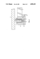
- FIG. 3 is a vertical sectional view through one component of the apparatus shown in FIGS. 1 and 2.
- a plurality of pallets 2 are adapted to move on fixed rails 16 in a slidable fashion.
- the fixed rails 16 are firmly supported by a frame structure which is not shown.
- Inwardly adjacent and slightly below each of the slide rails 16 is a transfer bar 8.
- the two transfer bars 8 are connected together by bridging pieces 9, so that they move together as a unit.
- One of the rails 8 (the uppermost rail in FIG. 1) has mounted to it a plurality of locating pins 10, the locating pins 10 being provided in pairs for each pallet position.
- Each locating pin 10 is secured to a mounting member 10a which is fixed on the rail 8, and is adapted to be received in a vertical bore in the pallet 2 in known fashion.
- Each of the rails 8 has affixed thereto in pairs for each pallet position a number of plungers 4 which are mounted for vertical reciprocation with respect to the respective transfer bar 8.
- the transfer bar 8 has, at each plunger location, a threaded vertical bore 20 which firmly receives a threaded bushing 6, defining an internal smooth bore for slidably receiving the plunger 4.
- the plunger 4 has an enlarged head 22 at the bottom, against which a coil compression spring 18 pushes upwardly. The coil compression spring 18 is trapped between the head 22 and the bottom 24 of the bore 20.
- An oil drain outlet 26 is provided in communication with the bore 20.
- the plunger 4 engages a bottom surface of the pallet 2.
- the transfer bars 8 In order to exert upward force on the pallets 2, the transfer bars 8 must be lifted while they are moving longitudinally to shift the position of the pallets 2. The lift must be sufficient to reduce frictional drag between the pallet 2 and the slide rails 16, but insufficient to lift the pallet entirely off the slide rails 16.
- the vertical lift of the transfer bars 8 is accomplished by means of a plurality of arms 11 and a drag link 12 which is connected to the arms 11 by cross members 28.
- the arms 11 are slightly crooked, and are provided in pairs just outboard of the transfer bars 8.
- the pairs of arms 11 are each pivoted about a common horizontal axis 30 which runs transverse to the direction of the slide rails 16. Between each pair of arms 11 is mounted a freely rotating roller 14 on which the transfer bars 8 rest.
- a given pallet 2 would be first locked in place against the slide rails 16 by conventional locking means (not shown), whereupon a machine tool operation would be carried out on the workpiece mounted on the pallet. Then, the pallet would be unlocked. Next, the pallet would be slid along the slide rails 16 to the next sequential work station while simultaneously applying an upward force against the pallet which is sufficient to reduce the frictional drag between the pallet and the slide rails but is insufficient to lift the pallet off the slide rails. This is done by simultaneously moving the drag link 12 leftwardly in order to raise the transfer bars 8, and at the same time causing the transfer bars 8 to move longitudinally and thus carry the pallet to the next position. The transfer bars are actually moved longitudinally by appropriate means not forming a part of this invention. When the pallet has reached the next position, it is again locked in place using conventional locking equipment, and the next machine tool operation is performed on the workpiece.
Abstract
Description
Claims (5)
Applications Claiming Priority (2)
| Application Number | Priority Date | Filing Date | Title |
|---|---|---|---|
| CA571,797 | 1988-07-12 | ||
| CA000571797A CA1337689C (en) | 1988-07-12 | 1988-07-12 | Method and apparatus for moving pallets in automated machine tool assemblies |
Publications (1)
| Publication Number | Publication Date |
|---|---|
| US4901412A true US4901412A (en) | 1990-02-20 |
Family
ID=4138364
Family Applications (1)
| Application Number | Title | Priority Date | Filing Date |
|---|---|---|---|
| US07/245,919 Expired - Lifetime US4901412A (en) | 1988-07-12 | 1988-09-19 | Apparatus for moving pallets in automated machine tool assemblies |
Country Status (3)
| Country | Link |
|---|---|
| US (1) | US4901412A (en) |
| EP (1) | EP0426914A3 (en) |
| CA (1) | CA1337689C (en) |
Cited By (3)
| Publication number | Priority date | Publication date | Assignee | Title |
|---|---|---|---|---|
| US5062188A (en) * | 1991-01-14 | 1991-11-05 | Tri-Way Machine Ltd. | Transfer apparatus for moving pallets using hydraulic lift |
| US6155402A (en) * | 1998-05-14 | 2000-12-05 | Valiant Machine & Tool Inc. | Conveyor system |
| US6523676B2 (en) * | 2000-02-10 | 2003-02-25 | Shimadzu Mectem, Inc. | Continuous treatment apparatus |
Families Citing this family (3)
| Publication number | Priority date | Publication date | Assignee | Title |
|---|---|---|---|---|
| CA2033786C (en) * | 1991-01-08 | 1995-12-05 | Joel W. Jones | Method and apparatus for moving pallets using hydraulic lift |
| JP2004092697A (en) * | 2002-08-29 | 2004-03-25 | Chiba Dies:Kk | Gear |
| CN112743375B (en) * | 2020-12-30 | 2022-02-15 | 诸暨市昊和机械股份有限公司 | Tubular product feed arrangement for copper sheathing processingequipment |
Citations (5)
| Publication number | Priority date | Publication date | Assignee | Title |
|---|---|---|---|---|
| US2392169A (en) * | 1942-09-18 | 1946-01-01 | Greenlee Bros & Co | Machine tool |
| US3155217A (en) * | 1961-12-21 | 1964-11-03 | Cross Co | Transfer machine |
| US3213996A (en) * | 1963-06-20 | 1965-10-26 | Cross Co | Transfer mechanism |
| US4360097A (en) * | 1980-10-14 | 1982-11-23 | Brems John Henry | Precision registry with lift and carry transfer system |
| US4394897A (en) * | 1980-11-14 | 1983-07-26 | Brems John Henry | Pallet registry mechanism and transfer lift system |
Family Cites Families (1)
| Publication number | Priority date | Publication date | Assignee | Title |
|---|---|---|---|---|
| US4201284A (en) * | 1978-11-02 | 1980-05-06 | Brems John Henry | Pallet registry system |
-
1988
- 1988-07-12 CA CA000571797A patent/CA1337689C/en not_active Expired - Fee Related
- 1988-09-19 US US07/245,919 patent/US4901412A/en not_active Expired - Lifetime
-
1989
- 1989-11-07 EP EP19890311524 patent/EP0426914A3/en not_active Withdrawn
Patent Citations (5)
| Publication number | Priority date | Publication date | Assignee | Title |
|---|---|---|---|---|
| US2392169A (en) * | 1942-09-18 | 1946-01-01 | Greenlee Bros & Co | Machine tool |
| US3155217A (en) * | 1961-12-21 | 1964-11-03 | Cross Co | Transfer machine |
| US3213996A (en) * | 1963-06-20 | 1965-10-26 | Cross Co | Transfer mechanism |
| US4360097A (en) * | 1980-10-14 | 1982-11-23 | Brems John Henry | Precision registry with lift and carry transfer system |
| US4394897A (en) * | 1980-11-14 | 1983-07-26 | Brems John Henry | Pallet registry mechanism and transfer lift system |
Cited By (3)
| Publication number | Priority date | Publication date | Assignee | Title |
|---|---|---|---|---|
| US5062188A (en) * | 1991-01-14 | 1991-11-05 | Tri-Way Machine Ltd. | Transfer apparatus for moving pallets using hydraulic lift |
| US6155402A (en) * | 1998-05-14 | 2000-12-05 | Valiant Machine & Tool Inc. | Conveyor system |
| US6523676B2 (en) * | 2000-02-10 | 2003-02-25 | Shimadzu Mectem, Inc. | Continuous treatment apparatus |
Also Published As
| Publication number | Publication date |
|---|---|
| EP0426914A2 (en) | 1991-05-15 |
| EP0426914A3 (en) | 1992-03-11 |
| CA1337689C (en) | 1995-12-05 |
Similar Documents
| Publication | Publication Date | Title |
|---|---|---|
| US4253559A (en) | Pallet locating and clamping mechanism for a transfer machine | |
| US4061062A (en) | Method and a device for the automatic replacement of a workpiece to be machined on a machine-tool | |
| US20060101894A1 (en) | Press mounted cam | |
| CA1071015A (en) | Workpiece transfer mechanism | |
| US4485911A (en) | Transfer machine | |
| US4217978A (en) | Precise pallet locating and clamping arrangement for workpiece transfer mechanism | |
| US4901412A (en) | Apparatus for moving pallets in automated machine tool assemblies | |
| US4629384A (en) | Transfer and locator of workpieces for a gang machine | |
| US6648568B2 (en) | Linear blind broaching machine | |
| KR20040000088A (en) | Meterial movement method and device of assembly machine for automobile seat rail | |
| DE3545675A1 (en) | MANUFACTURING EQUIPMENT | |
| US3213996A (en) | Transfer mechanism | |
| US5813514A (en) | Automated end loading pallet system | |
| DE3247158A1 (en) | Shelving arrangement with at least one storage and retrieval unit | |
| US8925363B2 (en) | Split idle station assemblies for transfer press assemblies | |
| US5062188A (en) | Transfer apparatus for moving pallets using hydraulic lift | |
| DE4303916A1 (en) | Workpiece feed for a vertical lathe | |
| CN208304553U (en) | The removable support pillar flexible tray of heavy-load type | |
| US6427305B1 (en) | Part elevator having a transfer bar with CAM follower and slot | |
| CN216421733U (en) | Workpiece series connection pressing device | |
| US4739871A (en) | Device for lifting work pieces and work piece supports from a conveyor belt | |
| KR960000348Y1 (en) | An automatic exchange device of a laser device | |
| JPS61296923A (en) | Method for forming metal die arrangement of bending machine | |
| US3501028A (en) | Pallet handling machine | |
| DE1961567A1 (en) | Device for changing workpieces on machine tools |
Legal Events
| Date | Code | Title | Description |
|---|---|---|---|
| AS | Assignment |
Owner name: TRI-WAY MACHINE LTD., 6555 HAWTHORNE DR., WINDSOR, Free format text: ASSIGNMENT OF ASSIGNORS INTEREST.;ASSIGNOR:JONES, JOEL W.;REEL/FRAME:004950/0090 Effective date: 19880704 Owner name: TRI-WAY MACHINE LTD., 6555 HAWTHORNE DR., WINDSOR, Free format text: ASSIGNMENT OF ASSIGNORS INTEREST;ASSIGNOR:JONES, JOEL W.;REEL/FRAME:004950/0090 Effective date: 19880704 |
|
| STCF | Information on status: patent grant |
Free format text: PATENTED CASE |
|
| FEPP | Fee payment procedure |
Free format text: PAYOR NUMBER ASSIGNED (ORIGINAL EVENT CODE: ASPN); ENTITY STATUS OF PATENT OWNER: LARGE ENTITY |
|
| FPAY | Fee payment |
Year of fee payment: 4 |
|
| FEPP | Fee payment procedure |
Free format text: PAYER NUMBER DE-ASSIGNED (ORIGINAL EVENT CODE: RMPN); ENTITY STATUS OF PATENT OWNER: LARGE ENTITY Free format text: PAYOR NUMBER ASSIGNED (ORIGINAL EVENT CODE: ASPN); ENTITY STATUS OF PATENT OWNER: LARGE ENTITY |
|
| FPAY | Fee payment |
Year of fee payment: 8 |
|
| FEPP | Fee payment procedure |
Free format text: PAT HLDR NO LONGER CLAIMS SMALL ENT STAT AS INDIV INVENTOR (ORIGINAL EVENT CODE: LSM1); ENTITY STATUS OF PATENT OWNER: LARGE ENTITY |
|
| AS | Assignment |
Owner name: WILMINGTON TRUST COMPANY, AS TRUSTEE, DELAWARE Free format text: SECURITY AGREEMENT;ASSIGNOR:FEDERAL-MOGUL WORLD WIDE, INC. (MI CORPORATION);REEL/FRAME:011571/0001 Effective date: 20001229 |
|
| FPAY | Fee payment |
Year of fee payment: 12 |
|
| AS | Assignment |
Owner name: 3060367 NOVA SCOTIA COMPANY, CANADA Free format text: PATENT LICENSE AND ASSIGNMENT AGREEMENT;ASSIGNOR:FEDERAL-MOGUL TRI-WAY LTD.;REEL/FRAME:012754/0636 Effective date: 20010921 |
|
| AS | Assignment |
Owner name: 3060367 NOVA SCOTIA COMPANY, ONTARIO Free format text: SECURITY INTEREST;ASSIGNOR:FEDERAL-MOGUL TRI-WAY LTD.;REEL/FRAME:013056/0112 Effective date: 20020520 |
|
| AS | Assignment |
Owner name: TRI-WAY MANUFACTURING TECHNOLOGIES CORP., CANADA Free format text: CHANGE OF NAME;ASSIGNOR:NOVA SCOTIA COMPANY;REEL/FRAME:016651/0830 Effective date: 20011024 |
|
| AS | Assignment |
Owner name: FEDERAL-MOGUL WORLDWIDE, INC., MICHIGAN Free format text: RELEASE OF SECURITY INTEREST RECORDED AT REEL/FRAME 011571/0001 AND 011466/0001;ASSIGNOR:WILMINGTON TRUST COMPANY, AS TRUSTEE;REEL/FRAME:020299/0377 Effective date: 20071217 |