US4901858A - Self-supporting display blister package - Google Patents
Self-supporting display blister package Download PDFInfo
- Publication number
- US4901858A US4901858A US07/235,582 US23558288A US4901858A US 4901858 A US4901858 A US 4901858A US 23558288 A US23558288 A US 23558288A US 4901858 A US4901858 A US 4901858A
- Authority
- US
- United States
- Prior art keywords
- side wall
- display package
- wall
- edge
- opening
- Prior art date
- Legal status (The legal status is an assumption and is not a legal conclusion. Google has not performed a legal analysis and makes no representation as to the accuracy of the status listed.)
- Expired - Lifetime
Links
Images


Classifications
-
- B—PERFORMING OPERATIONS; TRANSPORTING
- B29—WORKING OF PLASTICS; WORKING OF SUBSTANCES IN A PLASTIC STATE IN GENERAL
- B29C—SHAPING OR JOINING OF PLASTICS; SHAPING OF MATERIAL IN A PLASTIC STATE, NOT OTHERWISE PROVIDED FOR; AFTER-TREATMENT OF THE SHAPED PRODUCTS, e.g. REPAIRING
- B29C51/00—Shaping by thermoforming, i.e. shaping sheets or sheet like preforms after heating, e.g. shaping sheets in matched moulds or by deep-drawing; Apparatus therefor
- B29C51/26—Component parts, details or accessories; Auxiliary operations
- B29C51/30—Moulds
-
- B—PERFORMING OPERATIONS; TRANSPORTING
- B29—WORKING OF PLASTICS; WORKING OF SUBSTANCES IN A PLASTIC STATE IN GENERAL
- B29C—SHAPING OR JOINING OF PLASTICS; SHAPING OF MATERIAL IN A PLASTIC STATE, NOT OTHERWISE PROVIDED FOR; AFTER-TREATMENT OF THE SHAPED PRODUCTS, e.g. REPAIRING
- B29C51/00—Shaping by thermoforming, i.e. shaping sheets or sheet like preforms after heating, e.g. shaping sheets in matched moulds or by deep-drawing; Apparatus therefor
- B29C51/04—Combined thermoforming and prestretching, e.g. biaxial stretching
-
- B—PERFORMING OPERATIONS; TRANSPORTING
- B65—CONVEYING; PACKING; STORING; HANDLING THIN OR FILAMENTARY MATERIAL
- B65D—CONTAINERS FOR STORAGE OR TRANSPORT OF ARTICLES OR MATERIALS, e.g. BAGS, BARRELS, BOTTLES, BOXES, CANS, CARTONS, CRATES, DRUMS, JARS, TANKS, HOPPERS, FORWARDING CONTAINERS; ACCESSORIES, CLOSURES, OR FITTINGS THEREFOR; PACKAGING ELEMENTS; PACKAGES
- B65D75/00—Packages comprising articles or materials partially or wholly enclosed in strips, sheets, blanks, tubes, or webs of flexible sheet material, e.g. in folded wrappers
- B65D75/28—Articles or materials wholly enclosed in composite wrappers, i.e. wrappers formed by associating or interconnecting two or more sheets or blanks
- B65D75/30—Articles or materials enclosed between two opposed sheets or blanks having their margins united, e.g. by pressure-sensitive adhesive, crimping, heat-sealing, or welding
- B65D75/32—Articles or materials enclosed between two opposed sheets or blanks having their margins united, e.g. by pressure-sensitive adhesive, crimping, heat-sealing, or welding one or both sheets or blanks being recessed to accommodate contents
- B65D75/36—Articles or materials enclosed between two opposed sheets or blanks having their margins united, e.g. by pressure-sensitive adhesive, crimping, heat-sealing, or welding one or both sheets or blanks being recessed to accommodate contents one sheet or blank being recessed and the other formed of relatively stiff flat sheet material, e.g. blister packages, the recess or recesses being preformed
- B65D75/366—Articles or materials enclosed between two opposed sheets or blanks having their margins united, e.g. by pressure-sensitive adhesive, crimping, heat-sealing, or welding one or both sheets or blanks being recessed to accommodate contents one sheet or blank being recessed and the other formed of relatively stiff flat sheet material, e.g. blister packages, the recess or recesses being preformed and forming one compartment
-
- B—PERFORMING OPERATIONS; TRANSPORTING
- B65—CONVEYING; PACKING; STORING; HANDLING THIN OR FILAMENTARY MATERIAL
- B65D—CONTAINERS FOR STORAGE OR TRANSPORT OF ARTICLES OR MATERIALS, e.g. BAGS, BARRELS, BOTTLES, BOXES, CANS, CARTONS, CRATES, DRUMS, JARS, TANKS, HOPPERS, FORWARDING CONTAINERS; ACCESSORIES, CLOSURES, OR FITTINGS THEREFOR; PACKAGING ELEMENTS; PACKAGES
- B65D2207/00—Standing packages
Definitions
- the invention relates to self-supporting, vertically free-standing display packages for displaying a product. More particularly, the invention relates to a blister pack display package having a preformed product closure attached to a paperboard back and provided with a unitary support structure. Another aspect of the invention concerns its manufacture by molding a plastic sheet into said blister package in such manner as to advantageously strengthen said unitary support structure along the edge of its contact with the surface on which it stands.
- the blister package of the present invention concerns those situations wherein the blister package desirably is presented to the consumer in a plurality of independent packages, each free-standing vertically on a horizontal support surface. While in some types of packages the vertical support is provided by folded panels of paperboard, this invention pertains to packages in which the support is provided by a reinforced edge incorporated in the blister portion of the total package in cooperation with the edge of the paperboard backing member to which the blister portion is affixed.
- the blister comprises a vertical front wall; a C-shaped side wall; a planar bottom wall between the terminal edges of the C-shaped side wall, said bottom wall having a downward slope intersecting said front wall along a bottom, front edge, said bottom, front edge being a support edge adapted for supporting the entire package on a horizontal surface, in cooperation with the paperboard backing member bottom edge, said blister further including a marginal flange normal to the rear edge of the C-shaped side wall.
- the display package of the present invention comprises a molded, plastic enclosure having a forward wall; a side wall including a side wall section that forms an acute interior angle with said forward wall, and a side wall portion opposite the side wall section that forms an obtuse interior angle with the forward wall, and an opening opposite said forward wall, said side wall section being thicker proximate the forward wall than proximate the opening, said opening being sealable by cover means having an edge, said edge cooperating with the edge formed by the forward wall and the side wall section to support the display package in an upright position.
- the invention concerns molding plastic shapes, for example, an enclosure as described in the previous paragraph, which plastic shapes are characterized by having an acute interior angle conforming to a negative draft angle in the mold.
- the present invention is broadly drawn to a mold comprising an individual product mold having a first surface, a second surface adjacent thereto, and at least one third surface, at least a portion of which is opposite said second surface, said at least one third surface also being adjacent to the first surface, and a base member with which the individual product mold is integrally, preferably unitarily, constructed.
- the second surface corresponding, for example, to the forward wall of the previously described display package, is angled with respect to an imaginary horizontal plane, e.g., the plane of the plastic sheet superposed above the mold during the molding process.
- the first and third surfaces extend or depend from a surface of the base member that is parallel to the second surface, said first and third surfaces each being substantially vertical in orientation or forming positive draft angles with respect to said horizontal plane.
- the mold is a master mold which comprises a plurality of rows of individual product mold units, each row being a mirror image of an adjacent row, two such rows forming a repeating mold segment, as hereinafter described.
- the present invention concerns a process and system for molding plastic shapes with the mold previously described.
- a planar plastic sheet is placed above the individual product mold unit or the master mold, as the case may be, preferably softened to permit the planar plastic sheet to conform to the shape of the mold, and thereafter removed from the mold unit or master mold.
- air transport means allows a vacuum to be drawn and a back pressure provided to assist in the shaping and removal, respectively, of the plastic sheet from the mold.
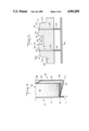
- FIG. 1 shows a front perspective view of the display package of the present invention, the package not containing a product.
- FIG. 2 is a front elevational view of FIG. 1, the package containing a representative product.
- FIG. 3 is a left-side elevational view of FIG. 1, the package containing a representative product.
- FIG. 4 is an enlarged sectional view of the device of FIG. 2 along lines 4--4.
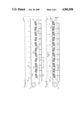
- FIGS. 5-10 are schematic diagrams of the molding operation When using a male mold.
- FIG. 11 shows in vertical cross-section a single repeating mold segment 120 of the mold segment shown schematically in FIG. 5.
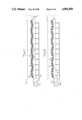
- FIG. 12 is a half-sectional view of the device of FIG. 2, identifying points of thickness measurement in connection with Example 2.
- FIGS. 1-3 there is shown a blister package 10 embodying the principles of this invention.
- Package 10 is produced from a single planar substrate, here shown as a paperboard blank 12 having a front display surface 15 and a blister pack structure or blister 18 adhesively or otherwise secured to display surface 15.
- Blister 18 is a formed structure having a product enclosure 20 and a support structure 22 which is a reinforced support edge.
- the body of product enclosure 20 extends outwardly from the paperboard blank 12 in a generally horizontal direction and is formed of a C-shaped (or horseshoe-shaped) side wall 23; a closed forward (or front) wall 25, the enclosure opposite wall 25 being an open back area 27 which is covered by the paperboard blank 12; a bottom wall 26 between the terminal edges 28, 29 of the C-shaped side wall 23, and a marginal flange 31 normal to rear edge 24 of the C-shaped side wall 23.
- the C-shaped side wall 23 slopes outwardly from forward wall 25 to rear edge 24.
- the bottom wall 26 slopes upwardly from forward wall 25 to rear edge 32 of the bottom wall 26 thereby forming with forward wall 25 an acute angle.
- the C-shaped side wall 23 forms a positive draft angle
- the bottom wall 26 forms a negative draft angle
- the negative angle draft associated with bottom wall 26 is equal to the positive angle draft associated with C-shaped side wall 23 (angle ⁇ of FIG. 3).
- the angle ⁇ is generally less than about 25°, i.e., the acute angle formed within the enclosure 20 by walls 25 and 26 is greater than about 65°.
- the angle ⁇ is between about 5° to aobut 20° (i.e. an acute interior angle of from about 70° to about 85°), and most preferably ⁇ is between about 75° to about 85° (an acute interior angle of from about 5° to about 15°).
- the bottom edge 13 of paperboard blank 12 lies substantially on the same horizontal plane as reinforced support edge 22, the reinforced support edge 22 being formed by the intersection of the forward wall 25 and the bottom wall 26.
- C-shaped side wall 23 includes a plurality of flutes 35 extending from edge 28 to edge 29.
- a chamfer 36 be included between the C-shaped side wall 23 and the forward wall 25, to facilitate removal from the mold and to provide additional strength to the blister.
- the display package 10 is intended to hold, for example, a tableted or extruded article such as a cylindrical toilet bowl cleaner disc 40 which, because of the construction of blister 18 and the relative sizes of product enclosure 20 and the product, may rest near the bottom wall 26, but which does not fill the enclosure 20.
- Recess 38 is provided to prevent the product 40 within the product enclosure 20 from moving.
- the oversized portion 39 of flange 31 is provided to allow removal of the blister from the display surface 15, the portion of the oversized area 39 not being affixed to the display surface 15.
- the thickness of blister 18 is greatest proximate the forward wall 25, and decreases generally in the direction of the flange 31. Accordingly, the support edge 22 has great strength, and the package 10 may be used in connection with a product of substantial weight.
- the flange 31 is seen to be thinner than the forward wall 25. Accordingly, deformation on cooling of the blister following molding is minimized, thereby ensuring a suitable seal to the display surface 15.
- product enclosure 20 is cup-shaped with a frusto-conical side wall 23, it will be understood that many shapes may be suitable for a product enclosure, and the term "cup-shaped" as used herein to describe the C-shaped wall 23 is intended to mean an enclosure which is closed or covered on all sides except the side covered by the paperboard blank 12 or some other similar covering.
- the flange 31 should be a predetermined minimal width to accommodate conventional heat-sealing equipment which must fit in the area between edge 13 of the paperboard blank 12 and the edge 32 of the bottom wall 26. While in the preferred embodiment, the product closure is totally sealed by having its opening 27 covered by paperboard blank 12, it will be understood that certain products may not need to be totally sealed.
- the display package 10 provides the product enclosure 20 proximate to the bottom edge 11, thereby providing the assembled package containing the product a low center of gravity.
- the outline of a typical product 40 it is not necessary for the product to conform to the shape of the blister package, nor is it necessary that the product conform to the shape of the lowermost portion thereof.
- the master mold 100 may comprise a plurality of individual blister product mold units 110.
- two adjacent blister mold units 110 comprise a single repeating mold segment 120.
- the master mold 100 may further comprise a plurality of rows of individual product mold units 110, which rows would be disposed perpendicular to the mold segment 120 shown in FIGS. 5 and 11, thereby forming a matrix of individual product mold units 110.
- FIG. 11 shows a single repeating mold segment 120 that comprises two individual product units 110 in male orientation; oppositely opposed, sloping base member segments 125 supporting said individual product mold units 110, the plurality of the base member segments 125 forming the base structure 127 for the master mold 100, and air transport means comprising conduits 135 drilled through the base member segments 125 and commonly connected at one end to header 136, the other ends forming apertures 131 in the top walls 112 of the individual product mold units 110.
- the apertures 131 are within the recesses 113 that correspond to the recess 38 of the blister 18.
- the master mold 100 may be made from any convenient material conventionally employed in the molding art.
- the molds are made of aluminum or other suitable metal, or cast epoxy resin.
- the side wall 126 corresponding to the bottom wall 26 of the blister 18 and the side wall 123 corresponding to the C-shaped side wall 23 of blister 18 are each vertical relative to horizontal, while planar base members 125 are sloped in an amount equal to the draft associated with the side wall 23 and the bottom wall 26 of the blister 18. Accordingly, the angles ⁇ ' shown in FIG. 11 are equal to the angle ⁇ and the angle ⁇ shown in FIG. 3. By such construction, the molded blisters 18 are vertically withdrawn from the individual product mold units 110.
- FIGS. 5-10 illustrating the sequence of the molding operation.
- a sheet of thermoformable plastic 150 has been unwound from roll 151 and is in position above the master mold 100, and below a source of heated air 155, which may comprise a fan or blower and a heating element.
- the plastic sheet 150 is positioned adjacently beneath device 160, which comprises a plurality of parallel wire filaments 161 that are in alignment with the alternating crests 170 and depressions 171 formed by the planar base member segments 125.
- Air transport lines 135 are connected to headers 136 via conduits 137. The conduits may be connected to the lines 135 by a conventional tap connection.
- each of the conduits 137 may be a flexible hose, in which case the header 136 may be stationary.
- the master mold 100 has been raised to meet the plastic sheet 150 backed by the wire filaments 161, the plastic sheet having been softened by the application of heat from heat source 155.
- the plastic sheet has begun to take the shape of the individual product mold units 110 and the wire filaments 161 have pinned the plastic sheet to the planar base member segments 125 at crests 170 and depressions 171.
- the master mold 100 is at its maximum upward travel, and the application of heat has ceased. Thereafter, as shown in FIG. 8, vacuum is drawn through each of the conduits 135, whereby the softened plastic is further urged to take the configuration of the individual product mold units 110.
- the plastic is softened sufficiently that air contained between the sheet 150 and the surface of the master mold 100 is withdrawn.
- cooling air is forced downwardly onto the plastic sheet, and a molded matrix 175 of blisters 18 is hardened, as shown in FIG. 9.
- Cooling air may be provided from fan 155, with its heating element off.
- a separate unit may be provided, which unit is slidable on tracks and positionable above the master mold 100.
- the master mold 100 is then lowered, and the molded matrix 175 of blisters 18 is removed from the master mold 100, with the assistance of pressurized air provided through the conduits 131, as shown in FIG. 10.
- the molded matrix 175 of blisters 18 is removed from above the master mold 100, thereby placing a new plastic sheet 150 into position, and the molded matrix of blisters 18 is then severed from the roll.
- the blisters 18 are then separated and trimmed.
- a plastic sheet was positioned above a master mold such as illustrated in FIGS. 5 and 11 such that the wire mesh was superposed above the sheet.
- the sheet was softened until a slight sag was observed by warm air from an overhead blower equipped with a heating coil.
- the master mold was then raised to meet the plastic sheet, the softened plastic conforming to the shape of each individual product mold unit.
- a vacuum of about 25 in. Hg was pulled, the plastic being drawn thereby into intimate contact with the surface of the mold.
- Cooling air was next directed onto the surface of the shaped plastic sheet, rigidifying same, and thereafter a back pressure of 100 psig was provided to the under surface of the shaped plastic sheet in contact with the mold. Essentially simultaneously, the master mold was lowered, and the shaped plastic sheet released. The shaped plastic sheet was removed from above the mold and cut into individual blister units.
- the forward wall 25 retains the original thickness of the plastic sheet--10 mil, and that the side wall 23 and the bottom wall 26 proximate forward wall 25 (Points B and I) are substantially thicker than proximate the flange 31 (Points D and G). Indeed, thickness of the flange 31 (Points E and F) is about half that of the forward wall 25 (Point A), and is amenable to sealing to a paperboard blank. It is further seen that the major portions of the side wall 23 and the bottom wall 26 are about half as thick as the forward wall 25, whereby removal of the molded sheet from the mold is facilitated.
- the thickness of the minor portions of the side wall 23 and bottom wall 26 proximate the forward wall 25 is retained as compared to the aforesaid major portions. Accordingly, the blister package is strongest proximate the forward wall where the greatest amount of contact occurs during shipping, display, and by consumer handling.
Abstract
Description
              TABLE I
______________________________________
Thickness (mils)
Point  Unit 1    Unit 2  Unit 3  Unit 4
                                       Unit 5
______________________________________
A      10        10      10      10    10
B      7         8       8       6     5
C      5         5       5       5     5
D      4         3       4       3     4
E      4         4       5       5     4
F      6         5       7       7     5
G      5         3       6       5     3
H      6         3       7       4     5
I      8         8       9       9     8
______________________________________
Claims (19)
Applications Claiming Priority (2)
| Application Number | Priority Date | Filing Date | Title |
|---|---|---|---|
| CA000548474A CA1293708C (en) | 1987-10-02 | 1987-10-02 | Blister package and its manufacture |
| CA548474 | 1987-10-02 |
Related Child Applications (1)
| Application Number | Title | Priority Date | Filing Date |
|---|---|---|---|
| US07422462 Division | 1989-10-17 |
Publications (1)
| Publication Number | Publication Date |
|---|---|
| US4901858A true US4901858A (en) | 1990-02-20 |
Family
ID=4136569
Family Applications (2)
| Application Number | Title | Priority Date | Filing Date |
|---|---|---|---|
| US07/235,582 Expired - Lifetime US4901858A (en) | 1987-10-02 | 1988-08-24 | Self-supporting display blister package |
| US07/711,360 Expired - Lifetime US5122328A (en) | 1987-10-02 | 1991-06-05 | Vacuum forming method for manufacturing self-supporting display package |
Family Applications After (1)
| Application Number | Title | Priority Date | Filing Date |
|---|---|---|---|
| US07/711,360 Expired - Lifetime US5122328A (en) | 1987-10-02 | 1991-06-05 | Vacuum forming method for manufacturing self-supporting display package |
Country Status (8)
| Country | Link |
|---|---|
| US (2) | US4901858A (en) |
| JP (1) | JPH01153467A (en) |
| AU (1) | AU617364B2 (en) |
| CA (1) | CA1293708C (en) |
| GB (1) | GB2210579B (en) |
| HK (1) | HK20392A (en) |
| NZ (1) | NZ226315A (en) |
| SG (1) | SG10592G (en) |
Cited By (32)
| Publication number | Priority date | Publication date | Assignee | Title |
|---|---|---|---|---|
| DE9017215U1 (en) * | 1990-12-20 | 1992-04-23 | E.S. Plastik Erwin Schmidt Gmbh & Co. Kg, 8391 Hutthurm, De | |
| US5244087A (en) * | 1989-05-01 | 1993-09-14 | Canon Kabushiki Kaisha | Container for accommodating ink jet head cartridge |
| DE29511242U1 (en) * | 1995-07-03 | 1995-11-02 | Colgate Palmolive Co | Container made of flexible plastic film |
| US5564569A (en) * | 1994-01-24 | 1996-10-15 | Adolf Illig Maschinenbau Gmbh & Co. | Package |
| US5657874A (en) * | 1990-11-06 | 1997-08-19 | Kraft Foods, Inc. | Food package having a compartmentalized rigid base tray |
| US5769228A (en) * | 1996-12-20 | 1998-06-23 | Gillette Canada Inc. | Display package |
| USD408278S (en) * | 1997-03-04 | 1999-04-20 | Gillette Canada Inc. | Blister package for a toothbrush |
| USD418408S (en) * | 1999-05-17 | 2000-01-04 | Trade Source International | Package |
| USD419065S (en) * | 1998-08-27 | 2000-01-18 | Trade Source International | Package |
| US6073795A (en) * | 1996-04-04 | 2000-06-13 | Winkler Forming, Inc. | Salad bowl with a lid |
| USD433939S (en) * | 1999-11-23 | 2000-11-21 | Trade Source International | Package design |
| USD434650S (en) * | 1999-04-20 | 2000-12-05 | Trade Source International | Package |
| US6170666B1 (en) * | 1999-04-27 | 2001-01-09 | Deslauriers International, Inc. | Tray packaging and display system |
| DE10033796C1 (en) * | 2000-07-12 | 2001-10-11 | Illig Maschinenbau Adolf | Production of blister packaging made from thermoplastic comprises sealing blister edges with support part, cooling, and heating transition region between dome and support part |
| USD450537S1 (en) | 2001-03-21 | 2001-11-20 | Pactiv Corporation | Bowl with lid |
| US6386368B1 (en) * | 1999-11-01 | 2002-05-14 | Eveready Battery Company, Inc. | Product packaging arrangement for shipping and display |
| USD457037S1 (en) | 2001-03-21 | 2002-05-14 | Pactiv Corporation | Bowl |
| USD461678S1 (en) | 2001-03-21 | 2002-08-20 | Pactiv Corporation | Lid for a bowl |
| EP1270442A2 (en) * | 2001-06-13 | 2003-01-02 | Giuseppe Righini | Packaging for metallic components and others, particularly for small blocks and twist drills |
| US6561374B2 (en) | 1996-04-04 | 2003-05-13 | Pactiv Corporation | Salad bowl with a lid |
| US20030148110A1 (en) * | 2002-02-01 | 2003-08-07 | Holbert Victor P. | Paperboard substrate for blister packaging |
| US20030196925A1 (en) * | 2002-04-19 | 2003-10-23 | Anna Dalessandro | Heat seal blister package having improved moisture vapor transmission barrier and method for forming same |
| US20070256951A1 (en) * | 2006-05-04 | 2007-11-08 | O'keefe Bill | Distressed packaging with extended visual element |
| US20090159486A1 (en) * | 2007-12-21 | 2009-06-25 | Senter L Nicholas | Shaped Packaging for a Refill |
| US20100101967A1 (en) * | 2008-10-29 | 2010-04-29 | Terry Ali | Bulk reclosable package display |
| US20110000811A1 (en) * | 2009-07-02 | 2011-01-06 | Dayan Maurice S | Clamshell package for holding and displaying consumer products |
| USD634626S1 (en) | 2008-06-20 | 2011-03-22 | The Procter & Gamble Company | Portion of a toothbrush package |
| US20110220680A1 (en) * | 2000-09-06 | 2011-09-15 | Allison Jane Danneels | Fabric additive articles and package therefor |
| US20140263384A1 (en) * | 2013-03-14 | 2014-09-18 | Land O'frost, Inc. | Food package |
| US20150291308A1 (en) * | 2013-03-14 | 2015-10-15 | Land O'frost, Inc. | Food package |
| US10456327B2 (en) * | 2015-08-28 | 2019-10-29 | Craig Robertson | Package for frozen nutrient pill |
| US20220289451A1 (en) * | 2021-03-12 | 2022-09-15 | Soli Organic Inc. | Produce Containers and Methods for Manufacturing and Packing Produce Containers |
Families Citing this family (10)
| Publication number | Priority date | Publication date | Assignee | Title |
|---|---|---|---|---|
| US5934475A (en) * | 1989-05-01 | 1999-08-10 | Canon Kabushiki Kaisha | Container for accommodating ink jet head cartridge |
| FR2648432B1 (en) * | 1989-06-16 | 1991-09-13 | Mecaplastic | DEVICE AND INSTALLATION FOR THE PACKAGING OF ANY PRODUCTS, FOR EXAMPLE OF FOOD PRODUCTS, IN TRAYS CLOSED BY A WELDED CLOSURE FILM |
| US5478338A (en) * | 1993-09-24 | 1995-12-26 | Reynard; Michael | Fiber optic sleeve for surgical instruments |
| US6068864A (en) * | 1996-07-12 | 2000-05-30 | Kraft Foods, Inc. | Method of imparting resistance to moisture and texture degradation to a baked product |
| BR9704788A (en) * | 1997-09-23 | 1999-09-08 | Unilever Nv | Process for increasing the dissolution of detergent tablets for dishwashers, combination of detergent composition with packaging system, and, packaging |
| DE19810478B4 (en) * | 1998-03-11 | 2004-10-07 | Bayerische Motoren Werke Ag | Process for the production of three-dimensionally deformed components |
| US6675527B1 (en) * | 2002-01-14 | 2004-01-13 | George N. Barere | Enclosed pest control device |
| JP2007298188A (en) * | 2006-04-27 | 2007-11-15 | Daikin Ind Ltd | Refrigerating device |
| GB2504103A (en) * | 2012-07-17 | 2014-01-22 | Jeyes Group Ltd | Cleaning product blister packaging |
| JP7210055B2 (en) * | 2021-04-12 | 2023-01-23 | 大成工業株式会社 | blister packaging container |
Citations (9)
| Publication number | Priority date | Publication date | Assignee | Title |
|---|---|---|---|---|
| US3093244A (en) * | 1961-11-02 | 1963-06-11 | Warner Brothers Co | Stand-up blister packages |
| FR1353019A (en) * | 1963-01-11 | 1964-02-21 | Rochette Cenpa | Display packaging |
| US3289830A (en) * | 1966-01-24 | 1966-12-06 | Master Lock Co | Display card mounted retainer and packaging device |
| US3402810A (en) * | 1967-06-27 | 1968-09-24 | New England Twine & Cordage Co | Twine dispensing device |
| US3599928A (en) * | 1968-11-06 | 1971-08-17 | Gardner H Strong | Discardable mold form |
| US4322001A (en) * | 1980-10-29 | 1982-03-30 | Hurley Patrick S | Protective case for a sports card or similar collectible article |
| US4702374A (en) * | 1986-04-21 | 1987-10-27 | Robert Kelner | Package assembly with testing feature for illuminated product |
| US4702368A (en) * | 1986-11-24 | 1987-10-27 | The Drackett Company | Vertically self supporting display package |
| US4781289A (en) * | 1987-03-30 | 1988-11-01 | The Drackett Company | Self-supporting display package |
Family Cites Families (6)
| Publication number | Priority date | Publication date | Assignee | Title |
|---|---|---|---|---|
| CA770011A (en) * | 1967-10-24 | Jones-Hinton James | Manufacture of shaped articles | |
| CA661566A (en) * | 1963-04-16 | The General Tire And Rubber Company | Vacuum forming thermoplastic seats and backs | |
| NL23290C (en) * | 1926-10-27 | |||
| FR2107840B1 (en) * | 1970-09-21 | 1975-07-18 | Philco Ford Corp | |
| US3988093A (en) * | 1974-11-25 | 1976-10-26 | Birchenough William D | Apparatus for heat forming a continuous web of plastic |
| JPS6089331A (en) * | 1983-10-21 | 1985-05-20 | Denki Kagaku Kogyo Kk | Apparatus for producing cylindrical molded body |
-
1987
- 1987-10-02 CA CA000548474A patent/CA1293708C/en not_active Expired - Fee Related
-
1988
- 1988-08-24 US US07/235,582 patent/US4901858A/en not_active Expired - Lifetime
- 1988-09-21 JP JP63235133A patent/JPH01153467A/en active Pending
- 1988-09-23 NZ NZ226315A patent/NZ226315A/en unknown
- 1988-09-30 AU AU23313/88A patent/AU617364B2/en not_active Ceased
- 1988-09-30 GB GB8823059A patent/GB2210579B/en not_active Expired - Lifetime
-
1991
- 1991-06-05 US US07/711,360 patent/US5122328A/en not_active Expired - Lifetime
-
1992
- 1992-02-03 SG SG105/92A patent/SG10592G/en unknown
- 1992-03-19 HK HK203/92A patent/HK20392A/en unknown
Patent Citations (9)
| Publication number | Priority date | Publication date | Assignee | Title |
|---|---|---|---|---|
| US3093244A (en) * | 1961-11-02 | 1963-06-11 | Warner Brothers Co | Stand-up blister packages |
| FR1353019A (en) * | 1963-01-11 | 1964-02-21 | Rochette Cenpa | Display packaging |
| US3289830A (en) * | 1966-01-24 | 1966-12-06 | Master Lock Co | Display card mounted retainer and packaging device |
| US3402810A (en) * | 1967-06-27 | 1968-09-24 | New England Twine & Cordage Co | Twine dispensing device |
| US3599928A (en) * | 1968-11-06 | 1971-08-17 | Gardner H Strong | Discardable mold form |
| US4322001A (en) * | 1980-10-29 | 1982-03-30 | Hurley Patrick S | Protective case for a sports card or similar collectible article |
| US4702374A (en) * | 1986-04-21 | 1987-10-27 | Robert Kelner | Package assembly with testing feature for illuminated product |
| US4702368A (en) * | 1986-11-24 | 1987-10-27 | The Drackett Company | Vertically self supporting display package |
| US4781289A (en) * | 1987-03-30 | 1988-11-01 | The Drackett Company | Self-supporting display package |
Cited By (45)
| Publication number | Priority date | Publication date | Assignee | Title |
|---|---|---|---|---|
| US5244087A (en) * | 1989-05-01 | 1993-09-14 | Canon Kabushiki Kaisha | Container for accommodating ink jet head cartridge |
| US5657874A (en) * | 1990-11-06 | 1997-08-19 | Kraft Foods, Inc. | Food package having a compartmentalized rigid base tray |
| DE9017215U1 (en) * | 1990-12-20 | 1992-04-23 | E.S. Plastik Erwin Schmidt Gmbh & Co. Kg, 8391 Hutthurm, De | |
| US5564569A (en) * | 1994-01-24 | 1996-10-15 | Adolf Illig Maschinenbau Gmbh & Co. | Package |
| DE29511242U1 (en) * | 1995-07-03 | 1995-11-02 | Colgate Palmolive Co | Container made of flexible plastic film |
| US6561374B2 (en) | 1996-04-04 | 2003-05-13 | Pactiv Corporation | Salad bowl with a lid |
| US6073795A (en) * | 1996-04-04 | 2000-06-13 | Winkler Forming, Inc. | Salad bowl with a lid |
| US5769228A (en) * | 1996-12-20 | 1998-06-23 | Gillette Canada Inc. | Display package |
| USD408278S (en) * | 1997-03-04 | 1999-04-20 | Gillette Canada Inc. | Blister package for a toothbrush |
| USD419065S (en) * | 1998-08-27 | 2000-01-18 | Trade Source International | Package |
| USD434650S (en) * | 1999-04-20 | 2000-12-05 | Trade Source International | Package |
| US6170666B1 (en) * | 1999-04-27 | 2001-01-09 | Deslauriers International, Inc. | Tray packaging and display system |
| USD418408S (en) * | 1999-05-17 | 2000-01-04 | Trade Source International | Package |
| US6386368B1 (en) * | 1999-11-01 | 2002-05-14 | Eveready Battery Company, Inc. | Product packaging arrangement for shipping and display |
| USD433939S (en) * | 1999-11-23 | 2000-11-21 | Trade Source International | Package design |
| DE10033796C1 (en) * | 2000-07-12 | 2001-10-11 | Illig Maschinenbau Adolf | Production of blister packaging made from thermoplastic comprises sealing blister edges with support part, cooling, and heating transition region between dome and support part |
| EP1172297A2 (en) | 2000-07-12 | 2002-01-16 | Illig, Adolf Maschinenbau GmbH & Co. | Method of manufacturing standing blister packs and apparatus for carrying out the method |
| US6550224B2 (en) | 2000-07-12 | 2003-04-22 | Adolf Illig Maschinenbau Gmbh & Co. | Method for producing stand-up blister packages, and apparatus for executing the method |
| US20110220680A1 (en) * | 2000-09-06 | 2011-09-15 | Allison Jane Danneels | Fabric additive articles and package therefor |
| USD450537S1 (en) | 2001-03-21 | 2001-11-20 | Pactiv Corporation | Bowl with lid |
| USD457037S1 (en) | 2001-03-21 | 2002-05-14 | Pactiv Corporation | Bowl |
| USD461678S1 (en) | 2001-03-21 | 2002-08-20 | Pactiv Corporation | Lid for a bowl |
| EP1270442A2 (en) * | 2001-06-13 | 2003-01-02 | Giuseppe Righini | Packaging for metallic components and others, particularly for small blocks and twist drills |
| EP1270442A3 (en) * | 2001-06-13 | 2003-05-07 | Giuseppe Righini | Packaging for metallic components and others, particularly for small blocks and twist drills |
| US20040118734A1 (en) * | 2001-06-13 | 2004-06-24 | Giuseppe Righini | Packaging for metallic findings and others, particularly small blocks and twist drills |
| US7213708B2 (en) * | 2001-06-13 | 2007-05-08 | Giuseppe Righini | Packaging for metallic findings and others, particularly small blocks and twist drills |
| US20030148110A1 (en) * | 2002-02-01 | 2003-08-07 | Holbert Victor P. | Paperboard substrate for blister packaging |
| WO2003066323A1 (en) * | 2002-02-01 | 2003-08-14 | International Paper Company | Paperboard substrate for blister packaging |
| US20070166492A1 (en) * | 2002-02-01 | 2007-07-19 | Holbert Victor P | Paperboard substrate for blister packaging |
| US7192640B2 (en) | 2002-02-01 | 2007-03-20 | International Paper Company | Paperboard substrate for blister packaging |
| US7165676B2 (en) | 2002-04-19 | 2007-01-23 | Smurfit-Stone Container Enterprises, Inc. | Heat seal blister package having improved moisture vapor transmission barrier and method for forming same |
| US20030196925A1 (en) * | 2002-04-19 | 2003-10-23 | Anna Dalessandro | Heat seal blister package having improved moisture vapor transmission barrier and method for forming same |
| US20070256951A1 (en) * | 2006-05-04 | 2007-11-08 | O'keefe Bill | Distressed packaging with extended visual element |
| US7614498B2 (en) * | 2006-05-04 | 2009-11-10 | Mattel, Inc. | Distressed packaging with extended visual element |
| US20090159486A1 (en) * | 2007-12-21 | 2009-06-25 | Senter L Nicholas | Shaped Packaging for a Refill |
| US7584846B2 (en) | 2007-12-21 | 2009-09-08 | S.C. Johnson & Son, Inc. | Shaped packaging for a refill |
| USD634626S1 (en) | 2008-06-20 | 2011-03-22 | The Procter & Gamble Company | Portion of a toothbrush package |
| US20100101967A1 (en) * | 2008-10-29 | 2010-04-29 | Terry Ali | Bulk reclosable package display |
| US20110000811A1 (en) * | 2009-07-02 | 2011-01-06 | Dayan Maurice S | Clamshell package for holding and displaying consumer products |
| US20140263384A1 (en) * | 2013-03-14 | 2014-09-18 | Land O'frost, Inc. | Food package |
| US20150291308A1 (en) * | 2013-03-14 | 2015-10-15 | Land O'frost, Inc. | Food package |
| US9505523B2 (en) * | 2013-03-14 | 2016-11-29 | Land O'frost, Inc. | Food package |
| US10456327B2 (en) * | 2015-08-28 | 2019-10-29 | Craig Robertson | Package for frozen nutrient pill |
| US11596577B2 (en) | 2015-08-28 | 2023-03-07 | Craig Robertson | Package for frozen nutrient pill |
| US20220289451A1 (en) * | 2021-03-12 | 2022-09-15 | Soli Organic Inc. | Produce Containers and Methods for Manufacturing and Packing Produce Containers |
Also Published As
| Publication number | Publication date |
|---|---|
| CA1293708C (en) | 1991-12-31 |
| NZ226315A (en) | 1991-04-26 |
| JPH01153467A (en) | 1989-06-15 |
| AU617364B2 (en) | 1991-11-28 |
| AU2331388A (en) | 1989-04-06 |
| GB2210579B (en) | 1991-11-13 |
| SG10592G (en) | 1992-03-20 |
| GB2210579A (en) | 1989-06-14 |
| GB8823059D0 (en) | 1988-11-09 |
| HK20392A (en) | 1992-03-27 |
| US5122328A (en) | 1992-06-16 |
Similar Documents
| Publication | Publication Date | Title |
|---|---|---|
| US4901858A (en) | Self-supporting display blister package | |
| CA1207715A (en) | Thermoplastic bag pack | |
| CA1298772C (en) | Process for making a vacuum skin package and product formed thereby | |
| US4570818A (en) | Reclosable container with label bridge | |
| US5048716A (en) | Cardboard container with reinforcing slits lined with synthetic material | |
| WO2000043275A9 (en) | Reclosable package and method | |
| US5950833A (en) | Inflated, stackable, bag package for crushable round articles | |
| US20110111099A1 (en) | Container For Sliced And Fluffed Food Products | |
| US20160176592A1 (en) | Two Compartment Plastic Containers and Food Product Pack Comprising Such Containers | |
| US10407210B2 (en) | Plastic cup with a thin outer sleeve and food product pack comprising such cups | |
| US3578235A (en) | Tray for carmels | |
| EP0024129B1 (en) | Record bagging apparatus | |
| US3899072A (en) | Nest for a caddy | |
| CA1313010C (en) | Blister package and its manufacture | |
| JPH07112759A (en) | Container group and its preparation | |
| AU1587292A (en) | Packaging system including small frame with integral lid, bag and external container | |
| JP3293103B2 (en) | Mainly plastic egg containers for business use | |
| JPH0352654Y2 (en) | ||
| JPH0642976Y2 (en) | Egg container | |
| JP3953038B2 (en) | Partition material | |
| US5484077A (en) | Packaging system including small frame with integral lid, bag and external container | |
| JPS6244899Y2 (en) | ||
| GB2104483A (en) | Moulded packaging for confectionery | |
| JPH03162237A (en) | Medical instrument container | |
| JP2594731Y2 (en) | Button type battery storage tray |
Legal Events
| Date | Code | Title | Description |
|---|---|---|---|
| AS | Assignment |
Owner name: BRISTOL-MYERS CANADA, INC., 390 BAY STREET, TORONT Free format text: ASSIGNMENT OF ASSIGNORS INTEREST.;ASSIGNOR:ANDERSON, JEFFREY;REEL/FRAME:004968/0199 Effective date: 19881028 Owner name: BRISTOL-MYERS CANADA, INC., ONTARIO Free format text: ASSIGNMENT OF ASSIGNORS INTEREST;ASSIGNOR:ANDERSON, JEFFREY;REEL/FRAME:004968/0199 Effective date: 19881028 |
|
| STCF | Information on status: patent grant |
Free format text: PATENTED CASE |
|
| AS | Assignment |
Owner name: DRACKETT COMPANY, 5020 SPRING GROVE AVENUE, CINCIN Free format text: ASSIGNMENT OF ASSIGNORS INTEREST.;ASSIGNOR:BRISTOL-MYERS CANADA, INC., A CORP. OF CA;REEL/FRAME:005620/0100 Effective date: 19910227 |
|
| FPAY | Fee payment |
Year of fee payment: 4 |
|
| AS | Assignment |
Owner name: DRACKETT COMPANY, THE, OHIO Free format text: CHANGE OF NAME;ASSIGNOR:NEW DRACKETT, INC.;REEL/FRAME:006667/0969 Effective date: 19930108 Owner name: NEW DRACKETT, INC., OHIO Free format text: MERGER;ASSIGNOR:DRACKETT COMPANY, THE;REEL/FRAME:006667/0985 Effective date: 19921231 |
|
| AS | Assignment |
Owner name: S. C. JOHNSON & SON, INC., WISCONSIN Free format text: ASSIGNMENT OF ASSIGNORS INTEREST;ASSIGNOR:DRACKETT COMPANY, THE;REEL/FRAME:006735/0129 Effective date: 19930625 |
|
| FEPP | Fee payment procedure |
Free format text: PAYOR NUMBER ASSIGNED (ORIGINAL EVENT CODE: ASPN); ENTITY STATUS OF PATENT OWNER: LARGE ENTITY |
|
| FPAY | Fee payment |
Year of fee payment: 8 |
|
| FPAY | Fee payment |
Year of fee payment: 12 |