US4901923A - Variable dilution ratio hose-end aspirator sprayer - Google Patents
Variable dilution ratio hose-end aspirator sprayer Download PDFInfo
- Publication number
- US4901923A US4901923A US07/255,814 US25581488A US4901923A US 4901923 A US4901923 A US 4901923A US 25581488 A US25581488 A US 25581488A US 4901923 A US4901923 A US 4901923A
- Authority
- US
- United States
- Prior art keywords
- mixing chamber
- sprayer
- mixing
- accordance
- container
- Prior art date
- Legal status (The legal status is an assumption and is not a legal conclusion. Google has not performed a legal analysis and makes no representation as to the accuracy of the status listed.)
- Expired - Lifetime
Links
Images
Classifications
-
- B—PERFORMING OPERATIONS; TRANSPORTING
- B05—SPRAYING OR ATOMISING IN GENERAL; APPLYING FLUENT MATERIALS TO SURFACES, IN GENERAL
- B05B—SPRAYING APPARATUS; ATOMISING APPARATUS; NOZZLES
- B05B7/00—Spraying apparatus for discharge of liquids or other fluent materials from two or more sources, e.g. of liquid and air, of powder and gas
- B05B7/24—Spraying apparatus for discharge of liquids or other fluent materials from two or more sources, e.g. of liquid and air, of powder and gas with means, e.g. a container, for supplying liquid or other fluent material to a discharge device
- B05B7/2402—Apparatus to be carried on or by a person, e.g. by hand; Apparatus comprising containers fixed to the discharge device
- B05B7/244—Apparatus to be carried on or by a person, e.g. by hand; Apparatus comprising containers fixed to the discharge device using carrying liquid for feeding, e.g. by suction, pressure or dissolution, a carried liquid from the container to the nozzle
- B05B7/2443—Apparatus to be carried on or by a person, e.g. by hand; Apparatus comprising containers fixed to the discharge device using carrying liquid for feeding, e.g. by suction, pressure or dissolution, a carried liquid from the container to the nozzle the carried liquid and the main stream of carrying liquid being brought together downstream of the container before discharge
Definitions
- the present invention relates to liquid sprayers, and more particularly to sprayers of the aspirator type that proportionally mix a liquid with water under pressure and provide a spray of the liquid/water mixture.
- Liquid aspirators are commonly employed to apply diluted solutions containing chemicals such as pesticides, fungicides, herbicides, and fertilizers to lawns or garden foliage.
- sprayers of this type are attached to a garden hose and the pressure of the water delivered through the hose is used to create a vacuum that causes a chemical solution in the sprayer to be aspirated into the water in order to provide a diluted solution that is subsequently sprayed.
- sprayers of this type include a container for holding the chemical solution to be diluted and sprayed, and a mixing head, the base portion of which serves as a cover for the chemical container.
- Such mixing heads generally include an adapter for connecting the mixing head to a standard garden hose, and a hand valve for turning on and off the flow of water from the garden hose.
- the mixing head also includes a venturi chamber in which water from the garden hose is mixed with undiluted chemical solution from the container.
- U.S. Pat. No. 3,770,205 discloses a sprayer wherein a portion of the incoming water is diverted into a chemical container for mixing with chemicals in the container. The mixture is then drawn back into a mixing head for further dilution with the nondiverted portion of incoming water.
- the sprayer includes a rotatable disk that enables the unit to be changed from a "liquid” mode to a "pellet” mode, depending upon whether the chemicals in the container are in liquid or solid form.
- a number of commercially available sprayers do provide for multiple dilution ratios. Multiple dilution ratio sprayers typically do not require chemical premixing and directly provide the desired concentration of chemical in the desired spray. These sprayers are more accurate because they eliminate the need for premixing. Furthermore, liquid chemicals in the container which are not used can be saved and returned to the package (can or bottle) containing the original undiluted chemicals.
- Multiple dilution ratio sprayers generally provide dilution ratio variation by either selectively proportioning the size of the opening in the passageway that extends from the chemical container to the mixing (venturi) chamber, or by varying the size of an auxiliary air vent opening which bleeds air into the mixing chamber in order to control the level of vacuum and the resulting syphoning action on chemical from the container.
- a multiple orificed selector such as a rotatable wheel or slidable stem interposed in the passageway or vent, is used to select the desired dilution ratio.
- U.S. Pat. Nos. 3,112,884 and 3,191,869 issued to Robert A. Gilmour, disclose spraying devices wherein the dilution ratio of chemical to water is adjusted by bleeding air into the mixing chamber to control the vacuum level therein. In such sprayers, the size of the air vent opening is adjusted to meet the desired dilution ratio, while the size of the aperture through which chemicals flow into the mixing chamber remains constant.
- the dilution ratio is controlled by changing both the diameter of the mixing chamber and the diameter of the opening through which the chemical flows into the mixing chamber.
- Such diameters can be changed by rotating a drum mounted in the mixing head, in which drum are contained a plurality of passageways of different diameter.
- a third type of sprayer is disclosed in U.S. Pat. No. 4,475,689.
- That sprayer includes a rotatable disk containing a plurality of apertures of different sizes. Adjacent each aperture is a small cavity that is connected to the aperture through a small channel. The size of each aperture and each cavity is specifically chosen for a particular dilution ratio.
- the disk is rotated until the desired aperture and cavity is aligned with the inlet to the mixing chamber. Undiluted water is then admitted into the selected cavity. That water is used to make an initial dilution of the chemical that is eventually drawn into the mixing chamber through the aperture. Subsequent to the initial dilution, the diluted chemical is then drawn into the mixing chamber where it is further diluted with water before being sprayed.
- a dilution cavity adjacent the aperture in the rotatable disk creates certain problems.
- a special "figure eight" shaped sealing ring is necessary to separately seal the dilution cavity from the aperture, and an additional chamber must be provided adjacent the mixing chamber in order to supply fresh water to the dilution cavity prior to the mixture of the diluted chemical into the mixing chamber.
- Such a system requires numerous small components, and is thus not only difficult to manufacture, but includes many openings and chambers that are prone to clogging. To further complicate matters, many of these openings and chambers are not accessible to a user, and thus may not be easily cleaned or unclogged.
- the present invention includes a multiple dilution ratio aspirator sprayer adapted to be connected to a hose for mixing a liquid with pressurized water from the hose to provide a spray of the mixture to grass, plants and the like.
- the sprayer includes a container for housing liquid to be mixed with water and a mixing head having a spray nozzle at one end thereof and means for attaching the mixing head to a hose at the other end thereof.
- the mixing head includes a single axis through-bore comprising a hose inlet and valve chamber, a spray nozzle discharge chamber, and a motive tube portion forming inline, upstream and downstream portions that define a coaxial mixing chamber of larger diameter therebetween to aspirate, mix and dilute liquid from the container with water flowing through the two portions of the motive tube.
- the sprayer also includes a feed tube for communicating liquid from the container to the inlet of the expansion or mixing chamber through any selected one of a plurality of apertures of different diameters formed in a control disk. By rotation of the control disk relative to the mixing head, each aperture is selectively alignable between the container feed tube and the mixing chamber inlet to control precisely the rate of flow of liquid from the container to the mixing chamber.
- the volume of the chamber and the size of the aperture through the control disk at a given flow rate through the motive tube controls the dilution ratio over a relatively large range of water flow rates through the motive tube.
- a cleaning orifice passing through the mixing head is circumferentially displaced from the inlet to the mixing chamber and the through bore so that upon rotation of the control disk, each of the plurality of apertures may be selectively aligned for cleaning as by a ramrod or wire of appropriate diameter to pass through the orifice as a guide through the selected aperture.
- Such cleaning assures not only continued suction, but more importantly, continued dilution at the selected ratio during aspiration of treating liquid from the container through the intake tube.
- the apertures through the rotatable disk may be as small as 0.0061 inches up to a maximum diameter of, say, 0.076 inches, thus giving a range of dilutions from 1 teaspoon to a gallon of water up to 8 ounces to a gallon of water.
- a method of cleaning the dilution apertures of an aspirator sprayer without disassembling of the mixer head from a liquid container for holding a treating fluid, such as fertilizers, fungicides, bacteriacontrol, insecticides or the like by positioning an aperture to be cleaned lateral to the main passageway and in line with a through passage in the spray head, but out of the pressurized water stream flowing through the spray head, so that by rotation of the control disk, any selected aperture is alignable either with the mixing chamber to control flow of treating fluid into the stream or with the circumferentially displaced cleaning aperture.
- a treating fluid such as fertilizers, fungicides, bacteriacontrol, insecticides or the like
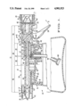
- FIG. 1 is a cross-sectional view of the multiple dilution ratio sprayer of the present invention
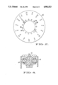
- FIG. 2 is a top view of a rotatable disk containing the variable dilution ratio apertures
- FIG. 3 is a top view of the mixing head of the sprayer.
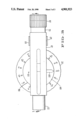
- FIG. 4 is a cross-sectional view taken along line 4--4 of FIG. 1.
- Sprayer 10 includes a container 12 for holding chemicals to be sprayed.
- Container 12 is preferably formed of a durable, chemical resistant plastic.
- Sprayer 10 also includes a mixing head 14 that includes a base portion 16 having threads 18 formed internally therein for releasably securing mixing head 14 to the top of container 12.
- Mixing head 14 further includes a main body 20 secured to base 16, as by screws 102, that mounts a spray nozzle assembly 22 at one end thereof and means for attaching a garden hose such as hose coupling assembly 24 mounted at the opposite end thereof.
- Main body 20 is particularly characterized by an internal passageway 21 formed therein as a single longitudinally extending cylindrical bore therethrough.
- main body 20 is preferably cast from a rigid, chemically resistant plastic with single through bore 21 forming (1) a control valve chamber portion 36, (2) a central portion 38 forming an upstream motive tube 39, and concentric mixing chamber 37, (3) a downstream motive bore portion 40, and (4) a discharge portion 42 for feeding the mixture of water and chemical to adjustable spray head assembly 22.
- Main body 20 may also be formed of metal such as aluminum or other comparable materials, either by casting or by cutting a single elongated bore with the four individual cylindrical portions, as by an automatic drilling machine tool.
- control valve chamber portion 36 of internal single passageway 21 through body 20 is formed with a relatively large diameter portion to accommodate a ball valve assembly 54 and a threaded garden hose coupler assembly 24, both of which will be described in greater detail below.
- Central portion 38 of passageway 21 defines both upstream motive tube section 39 and concentric mixing chamber section 37.
- a single sleeve or tubular insert 27 slidably engages the side wall of central portion 38, as by circumferential ridges 29.
- Sleeve 27 performs two functions. One function is: its length is proportioned to form precisely the volume of concentric mixing chamber 37 between its downstream end 33 and downstream end wall 35 of central portion 38.
- flange portion 23 of sleeve 27 forms a valve seat for ball 55 of ball valve assembly 54, against 0-ring 87 and the end wall 30 of control valve chamber 36.
- the through bore of sleeve 27, forming upstream motive tube portion 39, has substantially the same diameter as integral or molded downstream motive tube portion 40.
- mixing chamber 37, between the downstream end of insert 27 and the entry to molded portion 40 forms a chamber of closely controlled volume which is concentric with and substantially larger in diameter than the combined upstream and downstream portions of combined motive tube 38.
- mixing chamber 37 Because the diameter of mixing chamber 37 is larger than the diameters of motive tube sections 39 and 40, a vacuum is created in mixing chamber 37 due to the pressure difference. The magnitude of the vacuum is determined by the ratio of diameters of the motive tubes and the mixing chamber.
- an inlet passageway 80 connectable to tube 98 which extends to the bottom of container 12.
- Tube 98 admits undiluted chemical liquid into mixing chamber 37 in response to the vacuum created by flow through motive tube 38.
- Control of water flow through bore 21 is by ball valve assembly 54, when the lever 58 is rotated in the direction of arrow A, so that ball 55 aligns passageway 66 with the inlet to motive tube section 39.
- water from a garden hose connected to body 20 by hose coupling assembly 24 passes through upstream portion 39 of motive tube 28 in main passageway 21 to draw chemical liquid from container 12 for mixture with a given volume of water mixing chamber 37.
- the mixture after dilution is then drawn into the downstream portion 40 of motive tube 28 for emission through nozzle assembly 22 at the end of main body 20.
- a disk 82 having a multiplicity of selectable apertures 86, is rotatably mounted between base portion 16 and main body 20 of mixing head 14 to bring each aperture into alignment between mixing chamber inlet 80 and tube 98.
- Each of apertures 86 of rotatable disk 82 includes a recess 84 surrounding the aperture.
- One of these recesses is unperforated to prevent chemical from entering mixing chamber 25 even with water flowing through motive tube 28.
- a tubular hose fitting 88 is mounted within a recess 90 formed in base portion 16, and is urged against the bottom of rotatable disk 82 by means of coil spring 92 acting against collar 91.
- An O-ring 94 seals the top of fitting 88 against the bottom of rotatable disk 82 and 0-ring 96 seals main body 20 against the top of rotatable disk 82.
- Hose 98 is secured within hose fitting 88 and extends into the base of the container 12 for receiving the chemical solution to be admitted into mixing chamber 37.
- a filter assembly 100 is mounted at the end of hose 98 in order to prevent any particulate matter that might clog the passageways or a selected aperture 86 from entering mixing chamber 37.
- Bolts or screws 102 extend through base 16 of mixing head 14 and a central hub section 103 of main body 20 to secure base 16 to the main body in such a way that disk 82 may be rotated about hub 103 formed as a part of body 20.
- apertures 86 in disk 82 significantly smaller than apertures in prior art sprayers.
- the smallest aperture 86 in disk 82 of the present invention may be as small as 0.0061 inches in diameter
- the smallest aperture in the commercial sprayer made in accordance with U.S. Pat. No. 4,475,689 is about 0.0125 inches in diameter.
- Such difference in aperture sizes enables the sprayer of the present invention to be constructed in a novel and efficient design, using a minimum of components.
- Disk 82 including a plurality of apertures 86 of such dimensions, is made in accordance with a molding technique generally known to those skilled in the art.
- the pins that are used to form such small apertures 86 in the disk are extremely narrow, and thus subject to breaking or bending.
- the pins are mounted on a spring-biased seat, such that longitudinal forces acting on a pin may be absorbed by the spring-biased seat instead of damaging the pin.
- each aperture is of the desired size in order to ensure the intended dilution ratio. Accordingly, the proper size of the aperture is preferably verified by measuring the resistance that the aperture had to air flowing therethrough. With such a measuring technique, accurate measurements are achieved without having to consider microscopic aberrations or the roundness (or lack thereof) of the aperture.
- FIG. 3 as shown in plan the peripheral flanges 104, 106 of body 20 project laterally from longitudinal bore 21 in body 20 so as to partially cover disk 82.
- an indicator 108 is molded or otherwise marked for indicating which aperture of the disk 82 is in alignment with tube fitting 88.
- recess 84 which does not contain an aperture therein, is shown to be in alignment with feed tube fitting 88 and passageway 80.
- indicator 108 points to the legend "OFF”.
- the legend is circumferentially placed approximately 90° away from a particular recess 84 and aperture 86, to which the legend pertains.
- O-ring 96 forms a seal against disk 82 to prevent any liquid in container 12 from entering mixing chamber 37. Thus in that mode only water from the water hose is emitted from nozzle assembly 22.
- the sprayer is kept in operating order without disassembly to clean out flow control apertures 86 by providing a small clean-cut opening 110 in other peripheral range 106.
- Opening 110 is circumferentially spaced from inlet 80 to chamber 37 so as to be in alignment with one of the apertures 86 in rotatable disk 82 that is not in alignment with inlet 80.
- rotatable disk 82 is rotated until that aperture aligns with opening 110.
- a wire, having a diameter smaller than the smallest aperture 86 is then passed completely through opening 110 and the aperture in order to clean it.
- Nozzle assembly 22 mounted on the discharge end of main body 20 preferably includes tubular projection 26 for supporting spray nozzle 19.
- Tubular projection 26 includes an annular recess 49 for mounting an O-ring seal 57 at the outer end thereof, and an annular recess 59 for receiving an annular detent ring 5 projecting internally from nozzle 19.
- Nozzle assembly 22 also includes a shroud 51 for rotating nozzle to discharge spray in a desired direction. Assembly 22 is easily removed or reattached to the tubular projection 26 by means of a slight longitudinal force.
- Garden hose coupling assembly 24 is a substantially tubular component 65 having sections of varying diameters, one end of which forms a tubular flange 67 that functionally fits within the diameter of valve chamber portion 36 of through bore 21 of main body 20.
- O-ring seal 70 provides a fluid-tight seal between flange 67 and chamber 36.
- Collar 72 secures the garden hose coupling assembly 24 to outer surface 68 of chamber 36.
- the base end of garden hose coupling assembly 24 includes a rotatable hose coupler 74 having internal threads 75 that are adapted to attach to a standard garden hose coupler (not shown).
- Conical filter screen 78 is mounted within the opening adjacent threads 75 in order to filter out particulate matter in the water supply or hose that might clog the sprayer.
- the hose connecting end of component 65 includes an integral ring 63 facing an anti-syphon device 61 comprising a wall member 54 having a plurality of apertures 56 therein separating the open threaded end of the assembly 24 from the passage 63 through tubular component 65. Apertures 56 are arranged in a generally circular pattern in the wall 54. Water entering the garden hose assembly 24 must pass through the plurality of small apertures 56 to enter passageway 21.
- flexible annular diaphragm 50 is mounted against the downstream side of wall 54. Since diaphragm 50 is held only at the outer periphery, water pressure contacting it through apertures 56 deflects the diaphragm 50 away from wall 54 so that water flows through apertures 56. However, if fluid attempts to flow in the reverse direction, diaphragm 50 closes against the wall 54, to seal apertures 56. In such a position, fluid is unable to flow through diaphragm 50 and effectively prevents reverse flow through the hose assembly 24.
- valve 54 is located within control valve chamber 36 to control flow of water into bore 21 of main body 20.
- Valve 54 includes ball 55 that seats on O-ring 87 surrounding the opening through flange 23 of sleeve 27 and is rotatably secured to lever 58 by a pair of side panels 60 (see FIG. 4).
- Side panels 60 include projections 62 extending therefrom that positively lock within slots 64 in the sides of ball 55.
- O-ring seals 65 form a liquid tight seal around the projections 62 in order to prevent water from leaking out of valve chamber 36.
- ball 55 includes cylindrical bore 66 extending diametrically through its center.
- bore 66 is aligned so that water cannot flow into through bore 21.
- ball 56 rotates on its valve seat to the position shown in dashed lines in FIG. 1 such that the opening 66 is aligned with the garden hose coupling 24 and the central opening of upstream motive tube 39, thus enabling water to flow therethrough.
- a slide lock for holding valve lever 58 in the full flow position is provided by collar 72 being slidably moved axially along the outer surface of 68 valve chamber 36 by catch 73 so that it engages web 69 of lever 58 to lock lever 58 against coupling 74, as shown in phantom.
- the diameter of combined motive tube 38 determines the maximum flow rate of the sprayer.
- the upstream end of the sleeve 27 has a slightly rounded edge.
- base 16 of mixing head 12 includes a small aperture (not shown) that allows air to be vented into container 12 as liquid is drawn through hose 98 into mixing chamber 25. Such aperture allows air to be drawn into container 12, thereby preventing a vacuum or low pressure condition that would impede withdrawal of chemicals from container 12.
Abstract
Description
              TABLE 1
______________________________________
            Approximate    Intended Ratio
Aperture No.
            Diameter       (per gallon)
______________________________________
1           .0061          1       tsp
2           .0081          11/2    tsp
3           .0094          2       tsp
4           .0118          1       tbs
5           .0138          4       tsp
6           .0159          1       oz.
7           .0188          11/2    oz.
8           .023           2       oz.
9           .026           21/2    oz.
10          .0289          3       oz.
11          .0331          4       oz.
12          .038           5       oz.
13          .041           51/3    oz.
14          .076           8       oz.
______________________________________
Claims (23)
Priority Applications (2)
| Application Number | Priority Date | Filing Date | Title |
|---|---|---|---|
| US07/255,814 US4901923A (en) | 1988-10-11 | 1988-10-11 | Variable dilution ratio hose-end aspirator sprayer |
| CA000612103A CA1319916C (en) | 1988-10-11 | 1989-09-20 | Variable dilution ratio hose-end aspiration sprayer |
Applications Claiming Priority (1)
| Application Number | Priority Date | Filing Date | Title |
|---|---|---|---|
| US07/255,814 US4901923A (en) | 1988-10-11 | 1988-10-11 | Variable dilution ratio hose-end aspirator sprayer |
Publications (1)
| Publication Number | Publication Date |
|---|---|
| US4901923A true US4901923A (en) | 1990-02-20 |
Family
ID=22969982
Family Applications (1)
| Application Number | Title | Priority Date | Filing Date |
|---|---|---|---|
| US07/255,814 Expired - Lifetime US4901923A (en) | 1988-10-11 | 1988-10-11 | Variable dilution ratio hose-end aspirator sprayer |
Country Status (2)
| Country | Link |
|---|---|
| US (1) | US4901923A (en) |
| CA (1) | CA1319916C (en) |
Cited By (71)
| Publication number | Priority date | Publication date | Assignee | Title |
|---|---|---|---|---|
| US5213264A (en) * | 1990-10-11 | 1993-05-25 | Chevron Research And Technology Company | Spraying device with a replaceable cartridge |
| US5259557A (en) * | 1991-09-25 | 1993-11-09 | Ecolab Inc. | Solution proportioner and dispensing system |
| EP0588462A2 (en) * | 1992-08-18 | 1994-03-23 | Shop-Vac Corporation | Chemical intake system |
| US5332158A (en) * | 1992-12-16 | 1994-07-26 | Monsanto Company | Spraying device with an interchangeable cartridge |
| US5344074A (en) * | 1991-09-25 | 1994-09-06 | Ecolab Inc. | Dispensing apparatus having a removable variable proportioning and metering device |
| US5372310A (en) * | 1993-05-24 | 1994-12-13 | Green Garden, Inc. | Hose-end spraying apparatus |
| US5413280A (en) * | 1992-10-16 | 1995-05-09 | Taylor; William S. | Apparatus and method for dissolving and dispensing soluble compounds |
| US5419495A (en) * | 1994-02-25 | 1995-05-30 | Shop Vac Corporation | Auxiliary chemical intake system |
| US5443094A (en) * | 1993-06-10 | 1995-08-22 | Ecolab Inc. | Concentrated product dilution system |
| US5529244A (en) * | 1994-10-04 | 1996-06-25 | S. C. Johnson & Son, Inc. | Aspirator liquid blending device using multiple restrictors |
| US5544810A (en) * | 1990-04-23 | 1996-08-13 | S. C. Johnson & Son, Inc. | Precision-ratioed fluid-mixing device and system |
| US5765605A (en) * | 1996-01-19 | 1998-06-16 | Sc Johnson Commerical Markets, Inc. | Distributed concentrated chemical dispensing system |
| US5823430A (en) * | 1997-01-10 | 1998-10-20 | Clark, Jr.; George Donald | Automatic fertilizing apparatus |
| US5822968A (en) * | 1996-04-23 | 1998-10-20 | Savala; Rodney M. | Garden tool and sprayer |
| US5856671A (en) * | 1995-05-19 | 1999-01-05 | Cornell Research Foundation, Inc. | Capillary electrophoresis-mass spectrometry interface |
| US5862948A (en) * | 1996-01-19 | 1999-01-26 | Sc Johnson Commerical Markets, Inc. | Docking station and bottle system |
| US5964415A (en) * | 1996-05-28 | 1999-10-12 | Lego Irrigation Ltd. | Portable water--mixture dispenser |
| EP1022060A3 (en) * | 1999-01-22 | 2002-01-23 | Griffin LL.C | Method and apparatus for dispensing multiple-component flowable substances |
| US6345773B1 (en) * | 1998-02-06 | 2002-02-12 | S. C. Johnson & Son, Inc. | Aspiration-type sprayer |
| US6378785B1 (en) | 2000-08-30 | 2002-04-30 | Saint-Gobain Calmar Inc. | Hose-end aspiration-type sprayer |
| WO2002036267A1 (en) * | 2000-10-30 | 2002-05-10 | Bruce Alan Whiteley | Fluid mixer with rotatable eductor tube and metering orifices |
| US6425534B2 (en) * | 1998-11-05 | 2002-07-30 | Green Garden Products Company | Spraying apparatus having a sealing member with apertures |
| US20020105404A1 (en) * | 2001-02-05 | 2002-08-08 | Ehv-Weidmann Industries Inc. | Modular transformer lead support system |
| US20020185420A1 (en) * | 2001-06-06 | 2002-12-12 | Horstman Richard Lawrence | Sprayer and filter therefor |
| US20030034051A1 (en) * | 2000-06-14 | 2003-02-20 | The Procter & Gamble Company | Article for deionization of water |
| US6708901B2 (en) | 2001-01-12 | 2004-03-23 | Johnsondiversey, Inc. | Multiple function dispenser |
| US6749133B1 (en) * | 2000-08-11 | 2004-06-15 | Green Garden Products Company | Spraying apparatus with insert |
| US20040112984A1 (en) * | 2001-01-12 | 2004-06-17 | Hubmann Curtis H. | Multiple function dispenser |
| US20040135011A1 (en) * | 2000-04-03 | 2004-07-15 | Donald Shanklin | Single valve ready to use hose end sprayer |
| US20040173163A1 (en) * | 2003-03-07 | 2004-09-09 | Aritee Poletis Bond | Apparatus and method for shampooing dogs, horses and other animals |
| US6869028B2 (en) | 2000-06-14 | 2005-03-22 | The Procter & Gamble Company | Spraying device |
| US20050098656A1 (en) * | 2003-10-30 | 2005-05-12 | Saint-Gobain Calmar Inc. | Hose-end sprayer assembly |
| US20050103893A1 (en) * | 2003-11-13 | 2005-05-19 | Oms Investments, Inc. | Spraying device with interchangeable cartridge |
| US20050145270A1 (en) * | 2003-12-31 | 2005-07-07 | Ray R. K. | Pressure washer with injector |
| US20050155972A1 (en) * | 2003-12-31 | 2005-07-21 | Ray R. K. | Container and cap assembly for pressure washer |
| US20050173567A1 (en) * | 2004-02-11 | 2005-08-11 | Shanklin Donald J. | Single valve ready to use sprayer |
| US20050178854A1 (en) * | 2004-02-13 | 2005-08-18 | Saint-Gobain Calmar Inc. | Hose-end sprayer assembly |
| US20050184171A1 (en) * | 2004-02-20 | 2005-08-25 | Shanklin Donald J. | Single valve ready to use sprayer |
| US20050189436A1 (en) * | 2004-02-27 | 2005-09-01 | Shanklin Donald J. | Longitudinal valve ready to use hose end sprayer |
| US20050199751A1 (en) * | 2004-02-13 | 2005-09-15 | Shanklin Donald J. | Single valve ready to use hose end sprayer |
| US20050274822A1 (en) * | 2003-11-21 | 2005-12-15 | Robert Lyons | Spray system with chemical injector and water supply line |
| US20050284959A1 (en) * | 2004-06-24 | 2005-12-29 | Hubmann Curtis H | Vented dispenser |
| US20060091237A1 (en) * | 2004-10-28 | 2006-05-04 | Dodd Joseph K | Liquid sprayer assembly |
| US20060097073A1 (en) * | 2004-10-28 | 2006-05-11 | Dodd Joseph K | Hose-end sprayer assembly |
| US7063277B2 (en) | 2002-07-31 | 2006-06-20 | Hayes Products, Llc. | Single longitudinal valve ready to use hose end sprayer |
| US20060131335A1 (en) * | 2004-12-20 | 2006-06-22 | Hubmann Curtis H | Variable water flow and dilution chemical dispenser |
| US20060157587A1 (en) * | 2005-01-20 | 2006-07-20 | Flick Timothy G | Hose spray mixing device |
| US20070017011A1 (en) * | 2005-07-21 | 2007-01-25 | Futch Stephen J | Chemical administrator for treating wastewater from a water-consuming device in a self-contained bathroom system |
| US20070102540A1 (en) * | 2005-11-08 | 2007-05-10 | Mark Maclean-Blevins | System for failsafe controlled dispensing of liquid material |
| US20070102542A1 (en) * | 2005-11-08 | 2007-05-10 | Maclean-Blevins Mark T | System for failsafe controlled dispensing of liquid material |
| US7237728B1 (en) * | 2005-05-19 | 2007-07-03 | Rodney Laible | Hand-held dispenser |
| US7325752B2 (en) | 2004-02-20 | 2008-02-05 | Meadwestvaco Calmar, Inc. | Single valve ready to use hose end sprayer |
| US20090121040A1 (en) * | 2007-11-10 | 2009-05-14 | Theo Duncan | Liquid fertilizer, weed killer, and pesticide application device using exchangeable containers connected to an irrigation system |
| US20100059605A1 (en) * | 2008-09-09 | 2010-03-11 | The Fountainhead Group, Inc. | Sprayer |
| US7866626B1 (en) | 2006-03-01 | 2011-01-11 | Mark Maclean-Blevins | Hydraulically controlled in-line valve apparatus |
| USD650046S1 (en) | 2011-03-01 | 2011-12-06 | Smg Brands, Inc. | Sprayer |
| USD670982S1 (en) | 2011-03-01 | 2012-11-20 | Smg Brands, Inc. | Applicator |
| USD681470S1 (en) | 2010-01-08 | 2013-05-07 | Oms Investments, Inc. | Dispensing container |
| US20130115111A1 (en) * | 2011-11-03 | 2013-05-09 | Heraeus Medical Gmbh | Device and Method for Generating Vacuum for Vacuum Cementing Systems |
| US8557126B2 (en) | 2010-04-20 | 2013-10-15 | Stephen J. Futch | Chemical administrator for controllably treating wastewater |
| USD708301S1 (en) | 2013-03-15 | 2014-07-01 | Oms Investments, Inc. | Liquid sprayer |
| US20170001207A1 (en) * | 2015-07-02 | 2017-01-05 | Westrock Dispensing Systems, Inc. | Dosing dispensers and methods for using the same |
| US20170087566A1 (en) * | 2015-09-25 | 2017-03-30 | Westrock Dispensing Systems, Inc. | Dosing dispensers and methods for using the same |
| US9980430B2 (en) | 2011-03-01 | 2018-05-29 | Oms Investments, Inc. | Ready-to-use hose end sprayer |
| US10022742B2 (en) | 2011-03-01 | 2018-07-17 | Oms Investments, Inc. | Applicator with collapsible wand |
| US10138110B2 (en) | 2015-09-21 | 2018-11-27 | S. C. Johnson & Son, Inc. | Attachment and system for mixing and dispensing a chemical and diluent |
| US10596530B2 (en) | 2017-07-19 | 2020-03-24 | Chapin Manufacturing, Inc. | Variable venturi device with adjustable valve stem |
| DE102019208073A1 (en) * | 2019-06-04 | 2020-12-10 | Robert Bosch Gmbh | Spray device for dispensing liquids |
| USD930113S1 (en) | 2019-10-29 | 2021-09-07 | Chapin Manufacturing, Inc. | Wet/dry hose end sprayer |
| US11213841B2 (en) | 2019-08-29 | 2022-01-04 | Chapin Manufacturing, Inc. | Wet/dry hose end sprayer |
| WO2023024643A1 (en) * | 2021-08-23 | 2023-03-02 | 安徽科技学院 | Solution mixing device for diluting total phosphorus in surface water and capable of being prepared in proportion |
Citations (7)
| Publication number | Priority date | Publication date | Assignee | Title |
|---|---|---|---|---|
| US2754152A (en) * | 1953-03-13 | 1956-07-10 | Robert A Gilmour | Sprayers |
| US2788245A (en) * | 1953-05-15 | 1957-04-09 | Robert A Gilmour | Disk control valves for sprayers |
| US2981284A (en) * | 1959-07-24 | 1961-04-25 | J L Putnam Company Inc | Ball valve |
| US2991939A (en) * | 1959-09-28 | 1961-07-11 | Barco Mfg Co Inc | Fluid mixing and spraying device |
| US3319893A (en) * | 1966-06-13 | 1967-05-16 | Rodgers James Linn | Sprinkler |
| US3770205A (en) * | 1972-08-24 | 1973-11-06 | Jet X Corp | Sprayer with detergent or chemical additive feed |
| US4418869A (en) * | 1979-09-24 | 1983-12-06 | Healy James W | Hose mounted fluid mixing sprayer |
-
1988
- 1988-10-11 US US07/255,814 patent/US4901923A/en not_active Expired - Lifetime
-
1989
- 1989-09-20 CA CA000612103A patent/CA1319916C/en not_active Expired - Fee Related
Patent Citations (7)
| Publication number | Priority date | Publication date | Assignee | Title |
|---|---|---|---|---|
| US2754152A (en) * | 1953-03-13 | 1956-07-10 | Robert A Gilmour | Sprayers |
| US2788245A (en) * | 1953-05-15 | 1957-04-09 | Robert A Gilmour | Disk control valves for sprayers |
| US2981284A (en) * | 1959-07-24 | 1961-04-25 | J L Putnam Company Inc | Ball valve |
| US2991939A (en) * | 1959-09-28 | 1961-07-11 | Barco Mfg Co Inc | Fluid mixing and spraying device |
| US3319893A (en) * | 1966-06-13 | 1967-05-16 | Rodgers James Linn | Sprinkler |
| US3770205A (en) * | 1972-08-24 | 1973-11-06 | Jet X Corp | Sprayer with detergent or chemical additive feed |
| US4418869A (en) * | 1979-09-24 | 1983-12-06 | Healy James W | Hose mounted fluid mixing sprayer |
Cited By (153)
| Publication number | Priority date | Publication date | Assignee | Title |
|---|---|---|---|---|
| US5544810A (en) * | 1990-04-23 | 1996-08-13 | S. C. Johnson & Son, Inc. | Precision-ratioed fluid-mixing device and system |
| US5213264A (en) * | 1990-10-11 | 1993-05-25 | Chevron Research And Technology Company | Spraying device with a replaceable cartridge |
| US5344074A (en) * | 1991-09-25 | 1994-09-06 | Ecolab Inc. | Dispensing apparatus having a removable variable proportioning and metering device |
| US5259557A (en) * | 1991-09-25 | 1993-11-09 | Ecolab Inc. | Solution proportioner and dispensing system |
| AU661572B2 (en) * | 1992-08-18 | 1995-07-27 | Shop-Vac Corporation | Chemical intake system |
| EP0588462A3 (en) * | 1992-08-18 | 1994-06-15 | Shop Vac Corp | Chemical intake system |
| EP0588462A2 (en) * | 1992-08-18 | 1994-03-23 | Shop-Vac Corporation | Chemical intake system |
| US5413280A (en) * | 1992-10-16 | 1995-05-09 | Taylor; William S. | Apparatus and method for dissolving and dispensing soluble compounds |
| US5332158A (en) * | 1992-12-16 | 1994-07-26 | Monsanto Company | Spraying device with an interchangeable cartridge |
| US5372310A (en) * | 1993-05-24 | 1994-12-13 | Green Garden, Inc. | Hose-end spraying apparatus |
| US5443094A (en) * | 1993-06-10 | 1995-08-22 | Ecolab Inc. | Concentrated product dilution system |
| US5419495A (en) * | 1994-02-25 | 1995-05-30 | Shop Vac Corporation | Auxiliary chemical intake system |
| US5529244A (en) * | 1994-10-04 | 1996-06-25 | S. C. Johnson & Son, Inc. | Aspirator liquid blending device using multiple restrictors |
| US5856671A (en) * | 1995-05-19 | 1999-01-05 | Cornell Research Foundation, Inc. | Capillary electrophoresis-mass spectrometry interface |
| US5954240A (en) * | 1996-01-19 | 1999-09-21 | S. C. Johnson Commercial Markets, Inc. | Docking station and bottle system |
| US5765605A (en) * | 1996-01-19 | 1998-06-16 | Sc Johnson Commerical Markets, Inc. | Distributed concentrated chemical dispensing system |
| US6129125A (en) * | 1996-01-19 | 2000-10-10 | Sc Johnson Commercial Markets, Inc. | Docking station and bottle system |
| US5862948A (en) * | 1996-01-19 | 1999-01-26 | Sc Johnson Commerical Markets, Inc. | Docking station and bottle system |
| US5822968A (en) * | 1996-04-23 | 1998-10-20 | Savala; Rodney M. | Garden tool and sprayer |
| US5964415A (en) * | 1996-05-28 | 1999-10-12 | Lego Irrigation Ltd. | Portable water--mixture dispenser |
| US5823430A (en) * | 1997-01-10 | 1998-10-20 | Clark, Jr.; George Donald | Automatic fertilizing apparatus |
| US6345773B1 (en) * | 1998-02-06 | 2002-02-12 | S. C. Johnson & Son, Inc. | Aspiration-type sprayer |
| US6425534B2 (en) * | 1998-11-05 | 2002-07-30 | Green Garden Products Company | Spraying apparatus having a sealing member with apertures |
| EP1022060A3 (en) * | 1999-01-22 | 2002-01-23 | Griffin LL.C | Method and apparatus for dispensing multiple-component flowable substances |
| US6913209B2 (en) | 2000-04-03 | 2005-07-05 | Hayes Product, Llc. | Single valve ready to use hose end sprayer |
| US20040135011A1 (en) * | 2000-04-03 | 2004-07-15 | Donald Shanklin | Single valve ready to use hose end sprayer |
| US9062777B2 (en) | 2000-04-03 | 2015-06-23 | Meadwestvaco Calmar, Inc. | Single valve ready to use hose end sprayer |
| US20050284961A1 (en) * | 2000-04-03 | 2005-12-29 | Donald Shanklin | Single valve ready to use hose end sprayer |
| US20030034051A1 (en) * | 2000-06-14 | 2003-02-20 | The Procter & Gamble Company | Article for deionization of water |
| US6869028B2 (en) | 2000-06-14 | 2005-03-22 | The Procter & Gamble Company | Spraying device |
| US7381279B2 (en) | 2000-06-14 | 2008-06-03 | The Procter & Gamble Company | Article for deionization of water |
| US6749133B1 (en) * | 2000-08-11 | 2004-06-15 | Green Garden Products Company | Spraying apparatus with insert |
| US6378785B1 (en) | 2000-08-30 | 2002-04-30 | Saint-Gobain Calmar Inc. | Hose-end aspiration-type sprayer |
| AU778020B2 (en) * | 2000-08-30 | 2004-11-11 | Saint-Gobain Calmar Inc. | Hose-end aspiration-type sprayer |
| US20030137897A1 (en) * | 2000-10-30 | 2003-07-24 | Whiteley Bruce Alan | Fluid mixer with rotatable eductor tube and metering orifices |
| WO2002036267A1 (en) * | 2000-10-30 | 2002-05-10 | Bruce Alan Whiteley | Fluid mixer with rotatable eductor tube and metering orifices |
| US6877890B2 (en) | 2000-10-30 | 2005-04-12 | Bruce Alan Whiteley | Fluid mixer with rotatable educator tube and metering orifices |
| US9480995B2 (en) | 2001-01-12 | 2016-11-01 | Diversey, Inc. | Multiple function dispenser |
| US10328398B2 (en) | 2001-01-12 | 2019-06-25 | Diversey, Inc. | Multiple function dispenser |
| US7850095B2 (en) | 2001-01-12 | 2010-12-14 | Diversey, Inc. | Multiple function dispenser |
| US8016212B2 (en) | 2001-01-12 | 2011-09-13 | Diversey, Inc. | Multiple function dispenser |
| US20040155119A1 (en) * | 2001-01-12 | 2004-08-12 | Hubmann Curtis H. | Multiple function dispenser |
| US8398003B2 (en) | 2001-01-12 | 2013-03-19 | Diversey, Inc. | Multiple function dispenser |
| US8870094B2 (en) | 2001-01-12 | 2014-10-28 | Diversey, Inc. | Multiple function dispenser |
| US20080237369A1 (en) * | 2001-01-12 | 2008-10-02 | Johnsondiversey, Inc. | Multiple function dispenser |
| US20080179420A1 (en) * | 2001-01-12 | 2008-07-31 | Johnsondiversey, Inc. | Multiple function dispenser |
| US7370813B2 (en) | 2001-01-12 | 2008-05-13 | Johnsondiversey, Inc. | Multiple function dispenser |
| US7341206B2 (en) | 2001-01-12 | 2008-03-11 | Johnsondiversey, Inc. | Multiple function dispenser |
| US6708901B2 (en) | 2001-01-12 | 2004-03-23 | Johnsondiversey, Inc. | Multiple function dispenser |
| US20110095047A1 (en) * | 2001-01-12 | 2011-04-28 | Diversey, Inc. | multiple function dispenser |
| US20050274823A1 (en) * | 2001-01-12 | 2005-12-15 | Hubmann Curtis H | Multiple function dispenser |
| US9616441B2 (en) | 2001-01-12 | 2017-04-11 | Diversey, Inc. | Multiple function dispenser |
| US10850241B2 (en) | 2001-01-12 | 2020-12-01 | Diversey, Inc. | Multiple function dispenser |
| US20040112984A1 (en) * | 2001-01-12 | 2004-06-17 | Hubmann Curtis H. | Multiple function dispenser |
| US6988675B2 (en) | 2001-01-12 | 2006-01-24 | Johnson Diversey, Inc. | Multiple function dispenser |
| US7025289B2 (en) | 2001-01-12 | 2006-04-11 | Johnsondiversey, Inc. | Multiple function dispenser |
| EP1716930A1 (en) | 2001-01-12 | 2006-11-02 | JohnsonDiversey, Inc. | Multiple function dispenser |
| US20060113405A1 (en) * | 2001-01-12 | 2006-06-01 | Hubmann Curtis H | Multiple function dispenser |
| US20020105404A1 (en) * | 2001-02-05 | 2002-08-08 | Ehv-Weidmann Industries Inc. | Modular transformer lead support system |
| US7322534B2 (en) | 2001-06-06 | 2008-01-29 | The Procter And Gamble Company | Spraying device |
| US20020185420A1 (en) * | 2001-06-06 | 2002-12-12 | Horstman Richard Lawrence | Sprayer and filter therefor |
| US7410105B2 (en) | 2001-06-06 | 2008-08-12 | The Procter & Gamble Company | Sprayer and filter therefor |
| US7063277B2 (en) | 2002-07-31 | 2006-06-20 | Hayes Products, Llc. | Single longitudinal valve ready to use hose end sprayer |
| US7328857B2 (en) | 2002-07-31 | 2008-02-12 | Meadwestvaco Calmar, Inc. | Single longitudinal valve ready to use hose end sprayer |
| US20060255180A1 (en) * | 2002-07-31 | 2006-11-16 | Englhard Ronald F | Single longitudinal valve ready to use house end sprayer |
| US20060261187A1 (en) * | 2002-07-31 | 2006-11-23 | Englhard Ronald F | Single longitudinal valve ready to use hose end sprayer |
| US20040173163A1 (en) * | 2003-03-07 | 2004-09-09 | Aritee Poletis Bond | Apparatus and method for shampooing dogs, horses and other animals |
| US6948451B2 (en) | 2003-03-07 | 2005-09-27 | Aritee Poletis Bond | Apparatus and method for shampooing dogs, horses and other animals |
| US20050098656A1 (en) * | 2003-10-30 | 2005-05-12 | Saint-Gobain Calmar Inc. | Hose-end sprayer assembly |
| US7118049B2 (en) * | 2003-10-30 | 2006-10-10 | Meadwestvaco Corporation | Hose-end sprayer assembly |
| US20050103893A1 (en) * | 2003-11-13 | 2005-05-19 | Oms Investments, Inc. | Spraying device with interchangeable cartridge |
| US7156324B2 (en) | 2003-11-13 | 2007-01-02 | Oms Investments, Inc. | Spraying device with interchangeable cartridge |
| US8235310B2 (en) | 2003-11-13 | 2012-08-07 | Oms Investments, Inc. | Spraying device with interchangeable cartridge |
| US20060157588A1 (en) * | 2003-11-13 | 2006-07-20 | Oms Investments, Inc. | Spraying device with interchangeable cartridge |
| US9427755B2 (en) | 2003-11-13 | 2016-08-30 | Oms Investments, Inc. | Spraying device with interchangeable cartridge |
| US20100243760A1 (en) * | 2003-11-13 | 2010-09-30 | Oms Investments, Inc. | Spraying Device With Interchangeable Cartridge |
| US20050274822A1 (en) * | 2003-11-21 | 2005-12-15 | Robert Lyons | Spray system with chemical injector and water supply line |
| US20050155972A1 (en) * | 2003-12-31 | 2005-07-21 | Ray R. K. | Container and cap assembly for pressure washer |
| US20050145270A1 (en) * | 2003-12-31 | 2005-07-07 | Ray R. K. | Pressure washer with injector |
| US20050173567A1 (en) * | 2004-02-11 | 2005-08-11 | Shanklin Donald J. | Single valve ready to use sprayer |
| US7350722B2 (en) | 2004-02-11 | 2008-04-01 | Meadwestvaco Calmar, Inc. | Single valve ready to use sprayer |
| US7229030B2 (en) | 2004-02-13 | 2007-06-12 | Hayes Products, Llc. | Single valve ready to use hose end sprayer |
| US20050199751A1 (en) * | 2004-02-13 | 2005-09-15 | Shanklin Donald J. | Single valve ready to use hose end sprayer |
| US20050178854A1 (en) * | 2004-02-13 | 2005-08-18 | Saint-Gobain Calmar Inc. | Hose-end sprayer assembly |
| US7255293B2 (en) | 2004-02-13 | 2007-08-14 | Meadwestvaco Corporation | Hose-end sprayer assembly |
| US8201755B2 (en) | 2004-02-20 | 2012-06-19 | Meadwestvaco Calmar, Inc. | Single valve ready to use sprayer |
| US20050184171A1 (en) * | 2004-02-20 | 2005-08-25 | Shanklin Donald J. | Single valve ready to use sprayer |
| US7325752B2 (en) | 2004-02-20 | 2008-02-05 | Meadwestvaco Calmar, Inc. | Single valve ready to use hose end sprayer |
| US7631819B2 (en) | 2004-02-27 | 2009-12-15 | Meadwestvaco Calmar, Inc. | Longitudinal valve ready to use hose end sprayer |
| US20050189436A1 (en) * | 2004-02-27 | 2005-09-01 | Shanklin Donald J. | Longitudinal valve ready to use hose end sprayer |
| US20050284959A1 (en) * | 2004-06-24 | 2005-12-29 | Hubmann Curtis H | Vented dispenser |
| US7086610B2 (en) * | 2004-06-24 | 2006-08-08 | Johnsondiversey, Inc. | Vented dispenser |
| US20060097073A1 (en) * | 2004-10-28 | 2006-05-11 | Dodd Joseph K | Hose-end sprayer assembly |
| US7513442B2 (en) | 2004-10-28 | 2009-04-07 | Meadwestvaco Calmar, Inc. | Hose-end sprayer assembly |
| US7188786B2 (en) * | 2004-10-28 | 2007-03-13 | Meadwestvaco Corporation | Hose-end sprayer assembly |
| US7407117B2 (en) * | 2004-10-28 | 2008-08-05 | Meadwestvaco Calmar, Inc. | Liquid sprayer assembly |
| US20060091237A1 (en) * | 2004-10-28 | 2006-05-04 | Dodd Joseph K | Liquid sprayer assembly |
| US20080054098A1 (en) * | 2004-10-28 | 2008-03-06 | Dodd Joseph K | Hose-End Sprayer Assembly |
| US20080197214A1 (en) * | 2004-12-20 | 2008-08-21 | Johnsondiversey, Inc. | Variable water flow and dilution chemical dispenser |
| US7341207B2 (en) | 2004-12-20 | 2008-03-11 | Johnsondiversey, Inc. | Variable water flow and dilution chemical dispenser |
| US20060131335A1 (en) * | 2004-12-20 | 2006-06-22 | Hubmann Curtis H | Variable water flow and dilution chemical dispenser |
| US20060157587A1 (en) * | 2005-01-20 | 2006-07-20 | Flick Timothy G | Hose spray mixing device |
| US7296761B1 (en) * | 2005-05-19 | 2007-11-20 | Rodney Laible | Hand-held dispenser |
| US7237728B1 (en) * | 2005-05-19 | 2007-07-03 | Rodney Laible | Hand-held dispenser |
| US20070267519A1 (en) * | 2005-05-19 | 2007-11-22 | Rodney Laible | Hand-held dispenser |
| US20070017011A1 (en) * | 2005-07-21 | 2007-01-25 | Futch Stephen J | Chemical administrator for treating wastewater from a water-consuming device in a self-contained bathroom system |
| US8480012B2 (en) | 2005-11-08 | 2013-07-09 | Mark Maclean-Blevins | System for failsafe controlled dispensing of liquid material |
| US8690079B2 (en) | 2005-11-08 | 2014-04-08 | Mark Maclean-Blevins | System for failsafe controlled dispensing of liquid material |
| US20090261122A1 (en) * | 2005-11-08 | 2009-10-22 | Mark Maclean-Blevins | System for failsafe controlled dispensing of liquid material |
| US20090250527A1 (en) * | 2005-11-08 | 2009-10-08 | Mark Maclean-Blevins | System for failsafe controlled dispensing of liquid material |
| US7753288B2 (en) | 2005-11-08 | 2010-07-13 | Maclean-Blevins Mark T | System for failsafe controlled dispensing of liquid material |
| US20070102540A1 (en) * | 2005-11-08 | 2007-05-10 | Mark Maclean-Blevins | System for failsafe controlled dispensing of liquid material |
| US7566013B2 (en) | 2005-11-08 | 2009-07-28 | Mark Maclean-Blevins | System for failsafe controlled dispensing of liquid material |
| US20070102542A1 (en) * | 2005-11-08 | 2007-05-10 | Maclean-Blevins Mark T | System for failsafe controlled dispensing of liquid material |
| US7866626B1 (en) | 2006-03-01 | 2011-01-11 | Mark Maclean-Blevins | Hydraulically controlled in-line valve apparatus |
| US20090121040A1 (en) * | 2007-11-10 | 2009-05-14 | Theo Duncan | Liquid fertilizer, weed killer, and pesticide application device using exchangeable containers connected to an irrigation system |
| US8622320B2 (en) * | 2008-09-09 | 2014-01-07 | The Fountainhead Group, Inc. | Sprayer |
| US20140117117A1 (en) * | 2008-09-09 | 2014-05-01 | The Fountainhead Group, Inc. | Sprayer |
| US20100059605A1 (en) * | 2008-09-09 | 2010-03-11 | The Fountainhead Group, Inc. | Sprayer |
| CN102209593B (en) * | 2008-09-09 | 2015-06-10 | 水源集团公司 | Sprayer |
| CN102209593A (en) * | 2008-09-09 | 2011-10-05 | 水源集团公司 | Sprayer |
| CN104971837A (en) * | 2008-09-09 | 2015-10-14 | 水源集团公司 | Sprayer |
| US9302283B2 (en) * | 2008-09-09 | 2016-04-05 | The Fountainhead Group, Inc. | Sprayer |
| USD681470S1 (en) | 2010-01-08 | 2013-05-07 | Oms Investments, Inc. | Dispensing container |
| US8557126B2 (en) | 2010-04-20 | 2013-10-15 | Stephen J. Futch | Chemical administrator for controllably treating wastewater |
| USD864679S1 (en) | 2011-03-01 | 2019-10-29 | Oms Investments, Inc. | Applicator |
| USD852593S1 (en) | 2011-03-01 | 2019-07-02 | Oms Investments, Inc. | Applicator |
| USD736577S1 (en) | 2011-03-01 | 2015-08-18 | Oms Investments, Inc. | Applicator |
| USD999033S1 (en) | 2011-03-01 | 2023-09-19 | Oms Investments, Inc. | Applicator |
| USD779898S1 (en) | 2011-03-01 | 2017-02-28 | Oms Investments, Inc. | Applicator |
| US11744171B2 (en) | 2011-03-01 | 2023-09-05 | Oms Investments, Inc. | Ready-to-use hose end sprayer |
| US11338313B2 (en) | 2011-03-01 | 2022-05-24 | Oms Investments, Inc. | Applicator with collapsible wand |
| USD797529S1 (en) | 2011-03-01 | 2017-09-19 | Oms Investments, Inc. | Applicator |
| US9980430B2 (en) | 2011-03-01 | 2018-05-29 | Oms Investments, Inc. | Ready-to-use hose end sprayer |
| USD650046S1 (en) | 2011-03-01 | 2011-12-06 | Smg Brands, Inc. | Sprayer |
| US10022742B2 (en) | 2011-03-01 | 2018-07-17 | Oms Investments, Inc. | Applicator with collapsible wand |
| USD670982S1 (en) | 2011-03-01 | 2012-11-20 | Smg Brands, Inc. | Applicator |
| US9470245B2 (en) * | 2011-11-03 | 2016-10-18 | Heraeus Medical Gmbh | Device and method for generating vacuum for vacuum cementing systems |
| US20130115111A1 (en) * | 2011-11-03 | 2013-05-09 | Heraeus Medical Gmbh | Device and Method for Generating Vacuum for Vacuum Cementing Systems |
| USD708301S1 (en) | 2013-03-15 | 2014-07-01 | Oms Investments, Inc. | Liquid sprayer |
| US11534782B2 (en) * | 2015-07-02 | 2022-12-27 | Silgan Dispensing Systems Corporation | Dosing dispensers and methods for using the same |
| US10486176B2 (en) * | 2015-07-02 | 2019-11-26 | Silgan Dispensing Systems Corporation | Dosing dispensers and methods for using the same |
| US20170001207A1 (en) * | 2015-07-02 | 2017-01-05 | Westrock Dispensing Systems, Inc. | Dosing dispensers and methods for using the same |
| US10669146B2 (en) | 2015-09-21 | 2020-06-02 | S.C. Johnson & Son, Inc. | Attachment and system for mixing and dispensing a chemical and diluent |
| US10138110B2 (en) | 2015-09-21 | 2018-11-27 | S. C. Johnson & Son, Inc. | Attachment and system for mixing and dispensing a chemical and diluent |
| US9987641B2 (en) * | 2015-09-25 | 2018-06-05 | Silgan Dispensing Systems Corporation | Dosing dispensers and methods for using the same |
| US10413918B2 (en) | 2015-09-25 | 2019-09-17 | Silgan Dispensing Systems Corporation | Dosing dispensers and methods for using the same |
| US20170087566A1 (en) * | 2015-09-25 | 2017-03-30 | Westrock Dispensing Systems, Inc. | Dosing dispensers and methods for using the same |
| US10596530B2 (en) | 2017-07-19 | 2020-03-24 | Chapin Manufacturing, Inc. | Variable venturi device with adjustable valve stem |
| DE102019208073A1 (en) * | 2019-06-04 | 2020-12-10 | Robert Bosch Gmbh | Spray device for dispensing liquids |
| US11213841B2 (en) | 2019-08-29 | 2022-01-04 | Chapin Manufacturing, Inc. | Wet/dry hose end sprayer |
| USD930113S1 (en) | 2019-10-29 | 2021-09-07 | Chapin Manufacturing, Inc. | Wet/dry hose end sprayer |
| WO2023024643A1 (en) * | 2021-08-23 | 2023-03-02 | 安徽科技学院 | Solution mixing device for diluting total phosphorus in surface water and capable of being prepared in proportion |
Also Published As
| Publication number | Publication date |
|---|---|
| CA1319916C (en) | 1993-07-06 |
Similar Documents
| Publication | Publication Date | Title |
|---|---|---|
| US4901923A (en) | Variable dilution ratio hose-end aspirator sprayer | |
| EP0130188B1 (en) | Variable dilution ratio hose-end sprayer | |
| US4527740A (en) | Hose-end aspirator sprayer | |
| USRE29405E (en) | Spray apparatus | |
| EP0975432B1 (en) | An improved spraying device | |
| US8622320B2 (en) | Sprayer | |
| US6425534B2 (en) | Spraying apparatus having a sealing member with apertures | |
| US4369921A (en) | Hose-end sprayer | |
| EP1184084B1 (en) | Hose-end aspiration-type sprayer | |
| US3188055A (en) | Mixing device | |
| US3381899A (en) | Spray gun | |
| US20220126312A1 (en) | Wet/dry hose end sprayer | |
| JP2008113644A (en) | Device for preparing and spraying chemical solution |
Legal Events
| Date | Code | Title | Description |
|---|---|---|---|
| AS | Assignment |
Owner name: CHEVRON RESEARCH COMPANY, CALIFORNIA Free format text: ASSIGNMENT OF ASSIGNORS INTEREST.;ASSIGNORS:MC ROSKEY, PETER K.;HAVLOVITZ, PAUL M.;REEL/FRAME:005293/0689 Effective date: 19881013 |
|
| STCF | Information on status: patent grant |
Free format text: PATENTED CASE |
|
| FEPP | Fee payment procedure |
Free format text: PAYOR NUMBER ASSIGNED (ORIGINAL EVENT CODE: ASPN); ENTITY STATUS OF PATENT OWNER: LARGE ENTITY |
|
| AS | Assignment |
Owner name: CHEVRON RESEARCH AND TECHNOLOGY COMPANY, CALIFORNI Free format text: CHANGE OF NAME;ASSIGNOR:CHEVRON RESEARCH COMPANY;REEL/FRAME:006393/0974 Effective date: 19900110 |
|
| AS | Assignment |
Owner name: CHEVRON RESEARCH AND TECHNOLOGY COMPANY Free format text: MERGER;ASSIGNOR:CHEVRON RESEARCH AND TECHNOLOGY COMPANY, A DELAWARE CORPORATION;REEL/FRAME:006633/0858 Effective date: 19921229 |
|
| AS | Assignment |
Owner name: MONSANTO COMPANY, MISSOURI Free format text: ASSIGNMENT OF ASSIGNORS INTEREST;ASSIGNOR:CHEVRON U.S.A. INC. A CORP. OF PENNSYLVANIA;REEL/FRAME:006705/0128 Effective date: 19930514 |
|
| FPAY | Fee payment |
Year of fee payment: 4 |
|
| SULP | Surcharge for late payment | ||
| FEPP | Fee payment procedure |
Free format text: PAYER NUMBER DE-ASSIGNED (ORIGINAL EVENT CODE: RMPN); ENTITY STATUS OF PATENT OWNER: LARGE ENTITY |
|
| FPAY | Fee payment |
Year of fee payment: 8 |
|
| FEPP | Fee payment procedure |
Free format text: PAYOR NUMBER ASSIGNED (ORIGINAL EVENT CODE: ASPN); ENTITY STATUS OF PATENT OWNER: LARGE ENTITY |
|
| AS | Assignment |
Owner name: OMS INVESTMENTS, INC., DELAWARE Free format text: ASSIGNMENT OF ASSIGNORS INTEREST;ASSIGNOR:MONSANTO COMPANY;REEL/FRAME:010043/0442 Effective date: 19990121 |
|
| AS | Assignment |
Owner name: CHASE MANHATTAN BANK, AS ADMINISTRATIVE AGENT, THE Free format text: SECURITY INTEREST;ASSIGNOR:OMS INVESTMENTS, INC.;REEL/FRAME:010506/0462 Effective date: 19990121 |
|
| FPAY | Fee payment |
Year of fee payment: 12 |
|
| AS | Assignment |
Owner name: OMS INVESTMENTS, INC., CALIFORNIA Free format text: TERMINATION AND RELEASE OF SECURITY INTEREST IN PATENT RIGHTS (PREVIOUSLY RECORDED AT REEL 10506 FRAME 0462);ASSIGNOR:JPMORGAN CHASE BANK, N.A., AS ADMINISTRATIVE AGENT (FORMERLY KNOWN AS THE CHASE MANHATTAN BANK);REEL/FRAME:016674/0409 Effective date: 20051019 |