US4907884A - Sample cell monitoring system - Google Patents
Sample cell monitoring system Download PDFInfo
- Publication number
- US4907884A US4907884A US07/059,157 US5915787A US4907884A US 4907884 A US4907884 A US 4907884A US 5915787 A US5915787 A US 5915787A US 4907884 A US4907884 A US 4907884A
- Authority
- US
- United States
- Prior art keywords
- cell
- sample
- light
- intensity
- light beam
- Prior art date
- Legal status (The legal status is an assumption and is not a legal conclusion. Google has not performed a legal analysis and makes no representation as to the accuracy of the status listed.)
- Expired - Lifetime
Links
Images


Classifications
-
- G—PHYSICS
- G01—MEASURING; TESTING
- G01N—INVESTIGATING OR ANALYSING MATERIALS BY DETERMINING THEIR CHEMICAL OR PHYSICAL PROPERTIES
- G01N21/00—Investigating or analysing materials by the use of optical means, i.e. using sub-millimetre waves, infrared, visible or ultraviolet light
- G01N21/17—Systems in which incident light is modified in accordance with the properties of the material investigated
- G01N21/47—Scattering, i.e. diffuse reflection
- G01N21/49—Scattering, i.e. diffuse reflection within a body or fluid
- G01N21/51—Scattering, i.e. diffuse reflection within a body or fluid inside a container, e.g. in an ampoule
-
- G—PHYSICS
- G01—MEASURING; TESTING
- G01N—INVESTIGATING OR ANALYSING MATERIALS BY DETERMINING THEIR CHEMICAL OR PHYSICAL PROPERTIES
- G01N21/00—Investigating or analysing materials by the use of optical means, i.e. using sub-millimetre waves, infrared, visible or ultraviolet light
- G01N21/01—Arrangements or apparatus for facilitating the optical investigation
- G01N21/03—Cuvette constructions
-
- G—PHYSICS
- G01—MEASURING; TESTING
- G01N—INVESTIGATING OR ANALYSING MATERIALS BY DETERMINING THEIR CHEMICAL OR PHYSICAL PROPERTIES
- G01N21/00—Investigating or analysing materials by the use of optical means, i.e. using sub-millimetre waves, infrared, visible or ultraviolet light
- G01N21/17—Systems in which incident light is modified in accordance with the properties of the material investigated
- G01N21/47—Scattering, i.e. diffuse reflection
- G01N2021/4704—Angular selective
- G01N2021/4711—Multiangle measurement
-
- G—PHYSICS
- G01—MEASURING; TESTING
- G01N—INVESTIGATING OR ANALYSING MATERIALS BY DETERMINING THEIR CHEMICAL OR PHYSICAL PROPERTIES
- G01N21/00—Investigating or analysing materials by the use of optical means, i.e. using sub-millimetre waves, infrared, visible or ultraviolet light
- G01N21/17—Systems in which incident light is modified in accordance with the properties of the material investigated
- G01N21/47—Scattering, i.e. diffuse reflection
- G01N21/49—Scattering, i.e. diffuse reflection within a body or fluid
- G01N21/51—Scattering, i.e. diffuse reflection within a body or fluid inside a container, e.g. in an ampoule
- G01N2021/513—Cuvettes for scattering measurements
Definitions
- the present invention concerns a new technique for monitoring the intensity of light directly incident on a scattering sample and correcting for both reflection losses and attenuation by the sample itself.
- light shall mean electromagnetic radiation, either monochromatic or of a broader frequency range, either unpolarized or polarized.
- small particle shall mean any particle whose size parameter is less than six.
- large particle shall mean a particle whose size parameter is greater than six.
- beam shall mean light propagating in a parallel or nearly parallel direction.
- beam diameter of an incident light source shall refer to the diameter of the beam measured between the points at which the intensity has fallen to 1/e 2 the intensity at the center of the beam.
- forward scattering direction shall mean all rays, i.e. directed line segments, propagating at an angle less than 90 degrees with respect to the direction of the incident beam.
- backward scattering direction shall mean all rays, i.e. directed line segments, propagating at an angle greater than 90 degrees with respect to the direction of the incident beam.
- the plane perpendicular to the direction of the wave's electric field is called the V-plane and said plane polarized light is vertically polarized with respect to said perpendicular plane.
- the corresponding H-plane is perpendicular to the V-plane and contains the incident wave's electric field.
- background effects shall mean any source of light detected by an instrument which is not due to the scattering of light from the sample.
- background contributions arising from interactions of the incident beam with the sample cell and related apparatus.
- any background produced by light scattering from a pure solvent itself is negligible.
- This invention is concerned with a new means for monitoring the intensity of light incident upon a scattering source so that the scattered light intensities recorded therefrom may be normalized accurately to the radiation flux incident thereon.
- the monitoring of the incident light source is achieved by means of two detectors; one monitors a fraction of the incident light before it enters the cell and the second monitors the light after it traverses and emerges from the cell.
- the square root of the product of these two values is then used to normalize each detected scattered signal by the light incident on the scattering sample by dividing each such detected scattered signal by said square root value.
- the square root of the product of these two measurements is shown to be proportional to the incident intensity at the sample.
- the monitoring invention is further disclosed in the context of the new flow cell of the parent application.
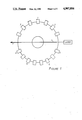
- FIG. 1 shows a top view of a cylindrical scattering cell surrounded by a set of collimated detectors and illuminated by a collimated light beam.
- FIG. 2 presents a perspective view of a preferred embodiment of the scattering cell showing the illumination source, the flow channel, the cell windows, and the fittings for introducing samples.
- FIG. 3 shows a flow fixture that is attached to the cylindrical sample cell to carry liquid-borne samples into or out of it.
- FIG. 4 shows the application of Snell's Law at the interface between two media.
- FIG. 5 is a top view of a preferred embodiment showing the sample cell, the normalization beam monitor, several typical detector means, and the illumination source with its monitor.
- the scattering properties of the sample cell or cuvette containing the solution may interfere with this determination, it is important to use a cell whose so-called "background" contributions will be minimal and affect the determinations least. Ideally, the cell will permit the measurement of the scattering properties of the solute particles or molecules at increasingly lower concentrations.
- FIG. 1 A typical detection system is shown in FIG. 1.
- An incident light source usually a monochromatic beam 1 such as produced by a laser passes through the sample cell.
- a monochromatic beam 1 such as produced by a laser passes through the sample cell.
- a set of discrete detectors 2 spaced circumferentially about this cell. Each detector is collimated so that its field of view includes only a very small volume at the center of the cell.
- FIG. 2 presents a perspective view of the scattering cell of the preferred embodiment of our invention. It consists of a cylinder 3 of glass or other transparent material of refractive index generally chosen close to the index of the solvent carrying the sample. Through the cylinder, a hole 4 is drilled along a diameter of the cylinder and lying in the plane of the detector array. The outer diameter of the cylinder and the hole interior surfaces are optically polished to remove any surface irregularities. Attached to each aperture of the cylinder is a fixture 5 containing an optical window 6 and a bore 7 to carry the sample into or out of the cell.
- FIG. 3 shows a greater detail of the fixtures 5 which, in the preferred embodiment of this invention, contains a tube 9 to convey the liquid-borne sample into or out of the cell hole 4.
- the light beam that passes through the cell must, in the preferred embodiment of this invention, be of even smaller cross section than the hole 4.
- a typical cell would have a hole diameter of 2.0 mm and be illuminated with a laser beam diameter of 0.4 mm such as is produced by a special He-Ne laser manufactured by Melles Griot.
- the refractive index of the cylinder the same as the refractive index of the liquid passing through the cell, the set-up would correspond to the geometry of the large radius of curvature structure of FIG.
- the beam passing through the cell of the present invention does not strike any surface within the field of view of any detector.
- the beam entrance and exit windows 6 are far removed from the center of the cell, which eliminates the background contributions associated with the beam traversing an air/glass/liquid interface.
- the sample volume contained within this cell is extremely small relative to the volume required for the traditional cell of such large radius of curvature. The actual volume of the sample would depend on the diameter of the hole 4 cut into the cylinder. Light scattered from this small sample volume will not be attenuated significantly as it passes through the glass cell region to the detectors. This also permits the examination of samples of greater particle density without the usual multiple scattering degradations that would be caused by the intervening particles in a comparably sized scattering cell, i.e. a cell where the glass region of the present invention were replaced by an additional liquid sample.
- refractive index between the solvent fluid passing through hole 4 and that of the glass cylindrical cell 3 surrounding it results in another important feature of our invention.
- these refractive indices will be quite close. As long as they are different, it will be possible to obtain measurements of light scattered at very small angles by particles or molecules illuminated by the highly collimated light source with negligible background contributions, as shall soon be demonstrated.
- the refractive index of the liquid n 1 will be that of water, 4/3, while that of the glass n 2 will be about 3/2.
- point 9 for the case of the scattering cell of the preferred embodiment, lies ahead, i.e. to the left, of the center of the cell 10, and is on the interface.
- a detector means detecting light at an angle ⁇ ' would be collimated to be centered on point 10.
- the scattering angle ⁇ of FIG. 4 represents the most important independent variable of a light scattering measurement. Accordingly, in the preferred embodiment of our invention, the detector means 2 of FIG. 1 should be placed so that there is a one-to-one correspondence with the set of ⁇ -angles selected for an experiment. An often used set of scattering angles ⁇ is selected such that the angles are equally spaced in sin ⁇ /2. The latter choice is particularly convenient for certain types of measurements related to molecular weight determinations or small particles whose refractive indices are very close to that of the medium surrounding them.
- the detectors surrounding the glass cell were spaced equidistantly in ⁇ ' or sin ⁇ '/2 the interpretation of the data so-detected in terms of the physical important scattering angle ⁇ would require the complex mathematical inversion of Eq. (1) for each measurement.
- Eq. (1) may be solved for ⁇ ' in terms of sin ⁇ /2 as follows: ##EQU1## For a typical case where the cell is optical glass of refractive index 3/2 and the sample is in a liquid of refractive index 4/3, a set of detectors at angle ⁇ would be placed according to the transformation table below:
- the average particle size parameter ⁇ becomes larger, the relative intensity of light scattered in the forward direction to that scattered into the backward direction becomes very large. For many types of instruments detecting scattered light at small angles, this becomes a troublesome problem as large forward scattering contributions may overwhelm and saturate the detector means monitoring forward scattering events. This is not true for our invention because of the unique attenuation of such forward scattered light.
- the fraction of scattered light flux reflected at the water glass interface 8 in terms of the angle of incidence, ⁇ may be determined from Fresnel's relations discussed, for example, in the textbook Light by R. W. Ditchburn.
- our invention permits the detection of light scattered at small angles without saturating the small angle detector means.
- the detection, classification, and measurement of particles of complex structure requires, therefore, that measurements be performed at many ( ⁇ , ⁇ ) locations that do not lie in a plane. If the incident light be plane polarized vertically with respect to a set of detectors lying along a great circle of the sphere/air interface, then there is another great circle at right angles to this with respect to which the incident light is horizontally polarized. Further details of the detection geometries are discussed in the cited Wyatt and Phillips' patent. The measurement and classification of such particles from the collected light scattering data are discussed in the patent of Wyatt and Quist. Note also that a sphere is not the only three dimensional structure for which our invention will apply, though it certainly provides the greatest flexibility for scattering measurements. Other useful three dimensional structures include cubes and many regular and irregular polyhedra.
- the hole 4 through the cell can contain additional structures such as a small spherical cavity at the center of the cell.
- This cavity would allow scattered light originating at the center of the cell to proceed along a radial line out of the cell and into the detectors. This would eliminate the refraction problem at the liquid/glass interface arising from the non-perpendicularity of the scattered ray at the interface.
- all detectors, except those whose field of view is obscured by hole 4 will be simultaneously viewing the center of the cavity.
- Such an arrangement would be important when, for example, viewing a single particle is desired, which requires many detectors viewing the same particle at the same location at the same time.
- the spherical cavity within the spherical cell could be easily fabricated, for example, by assembling the spherical cell from two hemispheres ground on a lens grinding machine. After cutting a sample introducting channel in each hemisphere and a central hemispherical cavity in each hemisphere, the two hemispheres and cavities would be polished and joined together by index matching cement.
- FIG. 5 shows a perspective view of the assembled cell complete with fixtures and surrounded with an array of detectors.
- a source monitor 13 monitors a fraction K of the incident source.
- a traditional form of such a monitor is based on a beam (14) splitter that would split off some fraction of the source beam before it enters the scattering cell.
- Other source monitoring configurations may be suitably employed as long as they monitor a fraction of the light source itself and are directly proportional thereto.
- the beam monitor 12 It will monitor the beam intensity after passing through the sample. If n is the number of particles per ml and ⁇ is the average scattering cross section per particle, then in a path length X, the intensity I of the illumination source will be attenuated according to Beer's Law as:
- I o the incident intensity
Abstract
The light intensity incident on a scattering sample contained in a scattering cell is monitored by simultaneous measurements of the light incident on the cell before entering it and the light transmitted through the cell after leaving it. Means to monitor the product of these signals is disclosed and how this product is related to the actual incident intensity at the sample is explained. The invention is presented in the context of the scattering cell of the parent application.
Description
Some of the developments and studies associated with this invention were performed under Contract #DAMD17-84-C-4155 from the U.S. Army Medical Research and Development Command. The Government has certain non-exclusive rights under the terms of this contract.
This is a continuation of application Ser. No. 861,863, filed May 12, 1986, now abandoned, which is a division of application Ser. No. 671,181, filed Nov. 15, 1985, now U.S. Pat. No. 4,616,927.
The present invention concerns a new technique for monitoring the intensity of light directly incident on a scattering sample and correcting for both reflection losses and attenuation by the sample itself.
As such it will find broad utility in various fields of light scattering determinations. Among some of the most important are those of the type discussed at length in the following patents and co-pending application by one of the inventors of the monitoring technique, namely:
U.S. Pat. No. 4,490,042
Title: Method for Determining the Properties of Wine
Inventor: Philip J. Wyatt
Filing Date: June 4, 1981
Issue Date: Dec. 25, 1984
Art Unit No.: 257
U.S. Pat. No. 4,548,500
Title: Process and Apparatus for Identifying or Characterizing Small Particles
Inventors: Philip J. Wyatt and Gregory M. Quist
Filing Date: June 22, 1982
Issue Date: Oct. 22, 1985
Art Unit No.: 255
U.S. Pat. No. 4,541,719
Title: Method and Apparatus for Characterizing Microparticles and Measuring Their Response to Their Environment
Inventor: Philip J. Wyatt
Filing Date: July 20, 1982
Issue Date: Sept. 17, 1985
Art Unit No.: 255
U.S. patent application Ser. No. 668,711
Title: Method and Apparatus for Measuring the Light Scattering Properties of Small Particles
Inventors: Philip J. Wyatt and Steven D. Phillips
Submis. Date: Nov. 5, 1984
The term "light" shall mean electromagnetic radiation, either monochromatic or of a broader frequency range, either unpolarized or polarized.
The term "size parameter" shall mean ρ, where ρ=2πa/λ, a is the mean particle radius, and λ is the wavelength of the incident electromagnetic radiation in the medium in which the particles are measured.
The term "small particle" shall mean any particle whose size parameter is less than six.
The term "large particle" shall mean a particle whose size parameter is greater than six.
The term "beam" shall mean light propagating in a parallel or nearly parallel direction.
The term "beam diameter" of an incident light source, with a Gaussian intensity profile, such as a laser, shall refer to the diameter of the beam measured between the points at which the intensity has fallen to 1/e2 the intensity at the center of the beam.
The term "forward scattering direction" shall mean all rays, i.e. directed line segments, propagating at an angle less than 90 degrees with respect to the direction of the incident beam.
The term "backward scattering direction" shall mean all rays, i.e. directed line segments, propagating at an angle greater than 90 degrees with respect to the direction of the incident beam.
For plane polarized light, the plane perpendicular to the direction of the wave's electric field is called the V-plane and said plane polarized light is vertically polarized with respect to said perpendicular plane. The corresponding H-plane is perpendicular to the V-plane and contains the incident wave's electric field.
The terms "background effects" and "background contributions" shall mean any source of light detected by an instrument which is not due to the scattering of light from the sample. We will be concerned solely with background contributions arising from interactions of the incident beam with the sample cell and related apparatus. We will assume any background produced by light scattering from a pure solvent itself is negligible.
This invention is concerned with a new means for monitoring the intensity of light incident upon a scattering source so that the scattered light intensities recorded therefrom may be normalized accurately to the radiation flux incident thereon. The monitoring of the incident light source is achieved by means of two detectors; one monitors a fraction of the incident light before it enters the cell and the second monitors the light after it traverses and emerges from the cell. The square root of the product of these two values is then used to normalize each detected scattered signal by the light incident on the scattering sample by dividing each such detected scattered signal by said square root value. In the detailed description of this invention, the square root of the product of these two measurements is shown to be proportional to the incident intensity at the sample. The monitoring invention is further disclosed in the context of the new flow cell of the parent application.
FIG. 1 shows a top view of a cylindrical scattering cell surrounded by a set of collimated detectors and illuminated by a collimated light beam.
FIG. 2 presents a perspective view of a preferred embodiment of the scattering cell showing the illumination source, the flow channel, the cell windows, and the fittings for introducing samples.
FIG. 3 shows a flow fixture that is attached to the cylindrical sample cell to carry liquid-borne samples into or out of it.
FIG. 4 shows the application of Snell's Law at the interface between two media.
FIG. 5 is a top view of a preferred embodiment showing the sample cell, the normalization beam monitor, several typical detector means, and the illumination source with its monitor.
Many important laboratory and industrial programs are involved with the measurement of fine particles in suspension by light scattering techniques. Foremost among them is the light scattering procedure for the determination of molecular weights of unknown solutes suspended in various types of solvents. Without going into the details of this procedure, which is described in many texts such as Kerker's book The Scattering of Light and Other Electromagnetic Radiation, the general measurement involves the preparation of a suspension of the unknown material followed by its illumination by a collimated beam of monochromatic light. The intensity of the light scattered by the suspension is then measured as a function of angle and solute concentration. Since the scattering properties of the sample cell or cuvette containing the solution may interfere with this determination, it is important to use a cell whose so-called "background" contributions will be minimal and affect the determinations least. Ideally, the cell will permit the measurement of the scattering properties of the solute particles or molecules at increasingly lower concentrations.
Many types of assays and bioassays, such as described by Wyatt in his two co-pending applications cited above or his chapter in the book edited by Charalambous entitled Analysis of Foods and Beverages, involve the preparation of aqueous suspensions. Subsequent measurement of these suspensions by light scattering means involves detecting very small changes in the measured light scattering properties of the solutions. Often, the accuracy of the results will be affected by background effects created by the scattering cell itself. Even the very simplest determinations of transmission or optical density, such as performed by conventional spectrophotometers of the type manufactured by Bausch and Lomb, depend critically on the background contributions of the liquid-containing cell. Furthermore, some compounds, such as those separated by means of liquid chromatography, are obtained in such small volumes that the cell containing them also must have a very small volume, typically on the order of microliters or less. Thus, "background" effects become increasingly important because of the close proximity of the sample cell liquid and air interfaces to the field of view of the detection system.
While studying many of the aforementioned measurements, we have discovered a cell structure and method of measurement that permits the examination by light scattering means of extremely small volumes of liquid-borne samples at virtually all scattering angles, no matter how small, without introducing significant background artifacts from the containing sample cell itself. This cell structure permits, in addition, the determination of the actual light flux incident upon the sample being examined, an often important requirement for many light scattering applications.
A typical detection system is shown in FIG. 1. An incident light source, usually a monochromatic beam 1 such as produced by a laser passes through the sample cell. Also shown in this figure is a set of discrete detectors 2 spaced circumferentially about this cell. Each detector is collimated so that its field of view includes only a very small volume at the center of the cell.
FIG. 2 presents a perspective view of the scattering cell of the preferred embodiment of our invention. It consists of a cylinder 3 of glass or other transparent material of refractive index generally chosen close to the index of the solvent carrying the sample. Through the cylinder, a hole 4 is drilled along a diameter of the cylinder and lying in the plane of the detector array. The outer diameter of the cylinder and the hole interior surfaces are optically polished to remove any surface irregularities. Attached to each aperture of the cylinder is a fixture 5 containing an optical window 6 and a bore 7 to carry the sample into or out of the cell.
FIG. 3 shows a greater detail of the fixtures 5 which, in the preferred embodiment of this invention, contains a tube 9 to convey the liquid-borne sample into or out of the cell hole 4. Note that the light beam that passes through the cell must, in the preferred embodiment of this invention, be of even smaller cross section than the hole 4. A typical cell would have a hole diameter of 2.0 mm and be illuminated with a laser beam diameter of 0.4 mm such as is produced by a special He-Ne laser manufactured by Melles Griot. As should be evident from FIGS. 1-3, were the refractive index of the cylinder the same as the refractive index of the liquid passing through the cell, the set-up would correspond to the geometry of the large radius of curvature structure of FIG. 1; yet the beam passing through the cell of the present invention does not strike any surface within the field of view of any detector. As seen in FIG. 2, the beam entrance and exit windows 6 are far removed from the center of the cell, which eliminates the background contributions associated with the beam traversing an air/glass/liquid interface. In addition, the sample volume contained within this cell is extremely small relative to the volume required for the traditional cell of such large radius of curvature. The actual volume of the sample would depend on the diameter of the hole 4 cut into the cylinder. Light scattered from this small sample volume will not be attenuated significantly as it passes through the glass cell region to the detectors. This also permits the examination of samples of greater particle density without the usual multiple scattering degradations that would be caused by the intervening particles in a comparably sized scattering cell, i.e. a cell where the glass region of the present invention were replaced by an additional liquid sample.
The difference of refractive index between the solvent fluid passing through hole 4 and that of the glass cylindrical cell 3 surrounding it results in another important feature of our invention. We have already stated that these refractive indices will be quite close. As long as they are different, it will be possible to obtain measurements of light scattered at very small angles by particles or molecules illuminated by the highly collimated light source with negligible background contributions, as shall soon be demonstrated. Typically, the refractive index of the liquid n1 will be that of water, 4/3, while that of the glass n2 will be about 3/2. Applying Snell's Law (see FIG. 4) to determine the refraction of a ray 1 striking the water-glass interface 8 at an angle θ yields the result
n.sub.1 sin (π/2-θ)=n.sub.2 sin (π/2-θ') (1)
where the angle of incidence is π/2-θ and the angle of refraction is π/2-θ'. Expanding the sine functions in Eq. (1) and collecting terms, immediately results in
n.sub.2 cos θ'=n.sub.1 cos θ, (2)
Note that point 9, for the case of the scattering cell of the preferred embodiment, lies ahead, i.e. to the left, of the center of the cell 10, and is on the interface. A detector means detecting light at an angle θ' would be collimated to be centered on point 10.
It is interesting to note that as the scattering angle θ becomes very small, i.e. approaches zero, the source of the scattering event 11 whose refracted rays are detected at θ moves to the right of the center of the cell 10. In the limit at θ=0, θ'=cos-1 (8/9)=27.27°. Thus, no matter how small the scattering angle θ, the refracted ray will be detected at an angle θ' sufficiently distant from all interfaces to permit said detector means to avoid receiving any direct contributions from the incident beam 1.
The scattering angle θ of FIG. 4 represents the most important independent variable of a light scattering measurement. Accordingly, in the preferred embodiment of our invention, the detector means 2 of FIG. 1 should be placed so that there is a one-to-one correspondence with the set of θ-angles selected for an experiment. An often used set of scattering angles θ is selected such that the angles are equally spaced in sin θ/2. The latter choice is particularly convenient for certain types of measurements related to molecular weight determinations or small particles whose refractive indices are very close to that of the medium surrounding them. If the detectors surrounding the glass cell were spaced equidistantly in θ' or sin θ'/2 the interpretation of the data so-detected in terms of the physical important scattering angle θ would require the complex mathematical inversion of Eq. (1) for each measurement. Instead, in a preferred embodiment of our invention, we place the detector means about the cell at those angles θ' that correspond to the selected set of scattering angles θ. For example, for equidistant spacing in sin θ/2 such that
0.2≦sin θ/2≦0.9, (3)
which is a range frequently found in scattering measurements, Eq. (1) may be solved for θ' in terms of sin θ/2 as follows: ##EQU1## For a typical case where the cell is optical glass of refractive index 3/2 and the sample is in a liquid of refractive index 4/3, a set of detectors at angle θ would be placed according to the transformation table below:
______________________________________
Table of Transformed Scattering Angles
sinθ/2   θ θ'
______________________________________
.2             23.07   35.13
.25            28.96   38.95
.3             34.92   43.21
.35            40.97   47.84
.4             47.16   52.81
.45            53.49   58.07
.5             60.00   63.61
.55            66.73   69.44
.6             73.74   75.59
.65            81.08   82.08
.7             88.85   88.98
.75            97.18   96.38
.8             106.26  104.41
.85            116.42  113.30
.9             128.32  123.45
______________________________________
To make a measurement at a very small scattering angle in the forward direction will require a very precise placement and collimation of the detector means, since refraction causes a small range of θ' values to correspond to a larger range of θ-values for θ near 0°. For a measurement at, say, θ=5.73°, the detector means would have to be placed at 27.82°, a scant 30' of arc from the limiting θ=0° value, where θ'=27.82°. Nevertheless, light scattered in this direction may be precisely intercepted by the carefully set detector means.
As the average particle size parameter ρ becomes larger, the relative intensity of light scattered in the forward direction to that scattered into the backward direction becomes very large. For many types of instruments detecting scattered light at small angles, this becomes a troublesome problem as large forward scattering contributions may overwhelm and saturate the detector means monitoring forward scattering events. This is not true for our invention because of the unique attenuation of such forward scattered light. As θ→0, the fraction of scattered light flux refracting into angle θ' becomes progressively smaller and becomes zero when θ=0. In FIG. 4, the fraction of scattered light flux reflected at the water glass interface 8 in terms of the angle of incidence, θ, may be determined from Fresnel's relations discussed, for example, in the textbook Light by R. W. Ditchburn. For the case of vertically polarized incident light, the reflected fraction ρw from liquid to glass is given by the relation ##EQU2## where θ is given by Eq. (2). Note that as θ→0, ρw →1, i.e. most of the light is reflected and only a decreasing fraction 1-ρw is transmitted to the small angle detector means. In the case or normal incidence θ and θ'→π/2. Taking this limiting case and applying Snell's law, we obtain
ρ.sub.w90° =(n.sub.1 -n.sub.2).sup.2 /(n.sub.1 +n.sub.2).sup.2 =(1/6).sup.2 /(17/6).sup.2 =0.34%
Thus by placing the scattering particles in a medium of refractive index less than that of the surrounding scattering cell, which is a natural procedure whenever particles are measured in solution, our invention permits the detection of light scattered at small angles without saturating the small angle detector means.
Although we have explained the key elements of our invention by means of a preferred cylindrical embodiment discussed above, it will be clear to those skilled in the art of light scattering that our invention applies equally to many other geometries and cell structures. The latter is of particular significance as it represents the hydrosol equivalent of the single particle aerosol particle analyser disclosed in the patent of Wyatt and Phillips. Highly irregular particles will scatter light as a complex function of both the polar angle θ and the azimuthal angle φ. The variation of intensity with φ at a fixed θ or a spherically symmetric particle, on the other hand, is a simple function of cos2 φ and sin2 φ. The detection, classification, and measurement of particles of complex structure requires, therefore, that measurements be performed at many (θ, φ) locations that do not lie in a plane. If the incident light be plane polarized vertically with respect to a set of detectors lying along a great circle of the sphere/air interface, then there is another great circle at right angles to this with respect to which the incident light is horizontally polarized. Further details of the detection geometries are discussed in the cited Wyatt and Phillips' patent. The measurement and classification of such particles from the collected light scattering data are discussed in the patent of Wyatt and Quist. Note also that a sphere is not the only three dimensional structure for which our invention will apply, though it certainly provides the greatest flexibility for scattering measurements. Other useful three dimensional structures include cubes and many regular and irregular polyhedra.
It is interesting to note that the transformed detector locations discussed above for the cylindrical cell embodiment of our invention apply equally well to a spherical cell. The angle of incidence of the scattered ray depends only on θ insofar as the application of Snell's law is concerned and is independent of φ. The azimuthal scattering angles φ would be selected to define different sets of detectors, each lying on a great circle, as described by Wyatt and Phillips.
It should be noted that the hole 4 through the cell can contain additional structures such as a small spherical cavity at the center of the cell. This cavity would allow scattered light originating at the center of the cell to proceed along a radial line out of the cell and into the detectors. This would eliminate the refraction problem at the liquid/glass interface arising from the non-perpendicularity of the scattered ray at the interface. Hence, all detectors, except those whose field of view is obscured by hole 4, will be simultaneously viewing the center of the cavity. Such an arrangement would be important when, for example, viewing a single particle is desired, which requires many detectors viewing the same particle at the same location at the same time. The spherical cavity within the spherical cell could be easily fabricated, for example, by assembling the spherical cell from two hemispheres ground on a lens grinding machine. After cutting a sample introducting channel in each hemisphere and a central hemispherical cavity in each hemisphere, the two hemispheres and cavities would be polished and joined together by index matching cement.
FIG. 5 shows a perspective view of the assembled cell complete with fixtures and surrounded with an array of detectors. A source monitor 13 monitors a fraction K of the incident source. A traditional form of such a monitor is based on a beam (14) splitter that would split off some fraction of the source beam before it enters the scattering cell. Other source monitoring configurations may be suitably employed as long as they monitor a fraction of the light source itself and are directly proportional thereto. Consider the beam monitor 12. It will monitor the beam intensity after passing through the sample. If n is the number of particles per ml and σ is the average scattering cross section per particle, then in a path length X, the intensity I of the illumination source will be attenuated according to Beer's Law as:
I=I.sub.o exp-(nσX), (8)
where, Io =the incident intensity. For many types of measurements, it is important that the scattered intensities detected be normalized to the intensity of the illumination incident upon the scattering particles. This normalization is particularly important in the measurement of molecular weights or monitoring critical growth processes. Some instruments split the incident beam and use the fraction removed thereby as this normalization factor Io. However, this value, so-obtained, may not well represent the actual intensity at the sample because of the attenuation of the intervening sample and reflections at the cell interfaces. Furthermore, this attenuation will vary from sample to sample. By introducing a beam monitor such as shown in FIG. 5, we are able to obtain very accurate representations of the normalized scattered intensities as follows.
Consider that the total sample path through the cell hole 4 is 2× and that the detectors 2 are collimated to view only the small volume at the center of the hole, a distance X from the beam entrance window 6 in FIG. 5. The intensity at the beam monitor 12 relative to the incident intensity at the entrance window is given by application of Beer's Law with the incorporation of the Fresnel reflection fraction f, at each air-glass interface and Fresnel reflection fraction g at each glass/liquid interface. Hence the total reflection fraction is F=f+g-fg whence:
I.sub.2 =I.sub.o (1-F).sup.2 exp-(2nσX). (9)
The intensity at the center of the sample, I1, on the other hand, is just
I.sub.2 =I.sub.o (1-F) exp-(nσX). (10)
Instead of normalizing the scattered intensities by Io, we should normalize by the factor of I1 of Eq. (10). However, the normalization factor ##EQU3## Furthermore, any normalization factor which is proportional to N is an equally suitable normalization factor. We are only concerned with the relative intensity at the center of the cell which varies from sample-to-sample due to differences in turbidities and from time-to-time due to the time varying intensity of the light source. ##EQU4## Hence, by monitoring a small fraction, K, of the incident source intensity at the external source monitor 13 and monitoring I2 at the beam monitor 12, one obtains N2 via Eq. (12). The value of K need not be known as N2 is only a relative normalization factor.
This final normalization obtained as the square root of the product of relative intensities at the beam monitor 12 and an external monitor 13 represents, therefore, the optimum normalization constant since it is always proportional to the real time value at the sample.
While there has hereinbefore been presented what is at present considered to be the preferred embodiment and process of our invention which has described a technique for measuring the scattered light intensities from small particles and molecules in solution over a broad range of scattering angles including those near zero degrees, it will be apparent to those of ordinary skill in the art of light scattering that many modifications and variations may be made therefrom without departing from the true spirit and scope of the invention. All such variations and modifications, therefore, are considered to be part of the invention.
Claims (12)
1. A method for normalizing the scattered intensities of light from particles suspended in a solvent and illuminated by a collimated light beam comprising the steps of
A. Measuring the intensity of light transmitted undeviated through the sample and external to the sample containing cell, Is ;
B. Measuring a fraction of the incident light source intensity before entering the cell, If ;
C. Dividing all measured scattering intensities at specified scattering angles by the quantity √If Is, where Is is the intensity value measured in step A and If is the intensity value measured in step B.
2. The method of claim 1 where the sample is confined to a channel and the illuminating light beam has a diameter much smaller than the diameter of the channel.
3. The method of claim 1 where the light beam is from a laser.
4. The method of claim 3 where the light from the laser is polarized.
5. The method of claim 1 where the fraction of the incident light source intensity is obtained from a beam splitter, said beam splitter dividing the incident beam into a source beam which illuminates the sample and a reference beam which illuminates the source beam monitor.
6. The method of claim 1 where the sample is contained in a cell between two transport windows and said illuminating collimated light beam passes through first transparent window means, then through said sample, and finally through second transparent window means.
7. The method of claim 6 where the medium external to each said transparent window means is air.
8. The method of claim 1 where the collimated light beam is plane polarized.
9. A sample cell monitor for generating a normalization factor by which means scattering light intensity values measured at a plurality of angles may be normalized by dividing each measured intensity by said normalizing factor, said sample cell containing a suspension of particles in a solvent solution that is illuminated by a collimated light beam that passes undeviated through the sample cell by entrance and exit window means provided therefore, and comprised of
A. Detector means for measuring a value proportional to the incident light beam intensity before said beam enters said sample cell;
B. Detector means for measuring a value proportional to the intensity of the light beam passing undeviated through the sample cell;
C. Multiplication means forming a value proportional to the product of the value from said incident light beam detector means and said undeviated light beam detector means;
D. Normalization generation means that forms normalization factor proportional to the square root of the product value of step C;
E. Division means to divide said scattered light intensity values by said normalization factor.
10. The monitor of claim 9 where the collimated light beam is a laser.
11. The monitor of claim 10 where the light from the laser is polarized.
12. The monitor of claim 9 where the incident light beam is split by a beam splitter before the said light beam enters the sample cell and where said split component is measured by said detector means of step A.
Priority Applications (1)
| Application Number | Priority Date | Filing Date | Title |
|---|---|---|---|
| US07/059,157 US4907884A (en) | 1984-11-15 | 1987-06-05 | Sample cell monitoring system |
Applications Claiming Priority (2)
| Application Number | Priority Date | Filing Date | Title |
|---|---|---|---|
| US06/671,181 US4616927A (en) | 1984-11-15 | 1984-11-15 | Sample cell for light scattering measurements |
| US07/059,157 US4907884A (en) | 1984-11-15 | 1987-06-05 | Sample cell monitoring system |
Related Parent Applications (1)
| Application Number | Title | Priority Date | Filing Date |
|---|---|---|---|
| US06861863 Continuation | 1986-05-12 |
Publications (1)
| Publication Number | Publication Date |
|---|---|
| US4907884A true US4907884A (en) | 1990-03-13 |
Family
ID=26738422
Family Applications (1)
| Application Number | Title | Priority Date | Filing Date |
|---|---|---|---|
| US07/059,157 Expired - Lifetime US4907884A (en) | 1984-11-15 | 1987-06-05 | Sample cell monitoring system |
Country Status (1)
| Country | Link |
|---|---|
| US (1) | US4907884A (en) |
Cited By (30)
| Publication number | Priority date | Publication date | Assignee | Title |
|---|---|---|---|---|
| WO1991017426A1 (en) * | 1990-05-07 | 1991-11-14 | Met One, Inc. | Split flow for uniform multisensor detection |
| US5701176A (en) * | 1995-07-28 | 1997-12-23 | Precision Detectors, Inc. | High temperature light scattering measurement device comprising a rigid extension tube |
| US6155489A (en) * | 1998-11-10 | 2000-12-05 | Ncr Corporation | Item checkout device including a bar code data collector and a produce data collector |
| US6332573B1 (en) | 1998-11-10 | 2001-12-25 | Ncr Corporation | Produce data collector and produce recognition system |
| US6407813B1 (en) | 1999-02-19 | 2002-06-18 | On-Line Instrumentation, Inc. | Measurement systems and methods for determining component particle concentrations in a liquid |
| US6431446B1 (en) | 1999-07-28 | 2002-08-13 | Ncr Corporation | Produce recognition system and method |
| US6441387B1 (en) * | 1999-06-30 | 2002-08-27 | The United States Of America As Represented By The Secretary Of The Army | Biological aerosol trigger (BAT) |
| US6549276B1 (en) * | 1998-10-30 | 2003-04-15 | Research Foundation Of State University Of New York | Method and apparatus for optical measurement of concentration and temperature of liquids |
| US6590652B2 (en) * | 2001-11-02 | 2003-07-08 | Pointsource Technologies, Inc. | Flow through light scattering device |
| US20040106167A1 (en) * | 1999-05-03 | 2004-06-03 | Icf Technologies, Inc. | Methods for evaluating sterilization procedures using a biological indicator |
| US6795183B2 (en) | 1999-02-19 | 2004-09-21 | Metron Instruments, Inc. | Measurement systems and methods for determining component particle concentrations in a liquid |
| US6819421B1 (en) | 2003-04-11 | 2004-11-16 | Point Source Technologies, Llc | Detection of new species of particles |
| US6930769B1 (en) | 2002-03-21 | 2005-08-16 | Pointsource Technologies, Llc | Optical sensor module tester |
| US6942989B2 (en) | 1999-05-03 | 2005-09-13 | Icf Technologies, Inc. | Methods, compositions and kits for biological indicator of sterilization |
| US6972424B1 (en) | 2002-04-16 | 2005-12-06 | Pointsource Technologies, Llc | High detection rate particle identifier |
| US7057724B1 (en) | 2002-03-21 | 2006-06-06 | Institute Of Critical Care Medicine | Particulate info to field units |
| US20060183183A1 (en) * | 1999-05-03 | 2006-08-17 | Icf Technologies, Inc. | Methods, compositions and kits for biological indicator of sterilization |
| US7221448B1 (en) * | 1999-06-18 | 2007-05-22 | Forschungszentrum Julich Gmbh | Test cell for a noble gas polarizer |
| US20100315637A1 (en) * | 2009-06-15 | 2010-12-16 | Wyatt Technology Corporation | Method and apparatus for measuring the scattered light signals from a liquid sample |
| US20110083994A1 (en) * | 2009-10-13 | 2011-04-14 | Sirota Eric B | Onset haze measurement apparatus and procedure |
| US20110134420A1 (en) * | 2008-07-22 | 2011-06-09 | Daisuke Matsumoto | Microchip and Analyzing Apparatus |
| WO2012093050A1 (en) * | 2011-01-04 | 2012-07-12 | Robert Bosch Gmbh | Measuring device for measuring particle concentrations by means of scattered light, and method for monitoring the measuring device |
| CN103063573A (en) * | 2011-10-18 | 2013-04-24 | 波特诺瓦分析有限公司 | Collimating system for multi-angle light diffusion detector |
| US20140354990A1 (en) * | 2013-06-03 | 2014-12-04 | Postnova Analytics Gmbh | Method For Measuring Scattered Light And Apparatus For Measuring Scattered Light |
| US9146192B2 (en) | 2012-05-17 | 2015-09-29 | Wyatt Technology Corporation | Integrated light scattering and ultraviolet absorption measurement system |
| CN105806807A (en) * | 2016-03-25 | 2016-07-27 | 中国人民解放军理工大学 | Natural seawater body scattering function in-situ measurement device and method |
| US20190107487A1 (en) * | 2017-10-06 | 2019-04-11 | Wyatt Technology Corporation | Optical flow cell assembly incorporating a replaceable transparent flow cell |
| US10408716B2 (en) | 2015-09-22 | 2019-09-10 | Wyatt Technology Corporation | Method and apparatus to measure multiple signals from a liquid sample |
| EP3695208A4 (en) * | 2019-01-02 | 2021-05-26 | M & J Scientific, Llc | Light scattering detectors and sample cells for the same |
| US11150175B2 (en) | 2019-01-02 | 2021-10-19 | M & J Scientific, Llc | Light scattering detectors and methods for the same |
Citations (5)
| Publication number | Priority date | Publication date | Assignee | Title |
|---|---|---|---|---|
| US3713743A (en) * | 1970-11-25 | 1973-01-30 | Agricultural Control Syst | Forward scatter optical turbidimeter apparatus |
| US4134679A (en) * | 1976-11-05 | 1979-01-16 | Leeds & Northrup Company | Determining the volume and the volume distribution of suspended small particles |
| US4167335A (en) * | 1977-12-16 | 1979-09-11 | Leeds & Northrup Company | Apparatus and method for linearizing a volume loading measurement utilizing particle scattering |
| US4515473A (en) * | 1984-09-13 | 1985-05-07 | Geo-Centers, Inc. | Photoelastic stress sensor signal processor |
| US4541719A (en) * | 1982-07-20 | 1985-09-17 | Wyatt Philip J | Method and apparatus for characterizing microparticles and measuring their response to their environment |
-
1987
- 1987-06-05 US US07/059,157 patent/US4907884A/en not_active Expired - Lifetime
Patent Citations (5)
| Publication number | Priority date | Publication date | Assignee | Title |
|---|---|---|---|---|
| US3713743A (en) * | 1970-11-25 | 1973-01-30 | Agricultural Control Syst | Forward scatter optical turbidimeter apparatus |
| US4134679A (en) * | 1976-11-05 | 1979-01-16 | Leeds & Northrup Company | Determining the volume and the volume distribution of suspended small particles |
| US4167335A (en) * | 1977-12-16 | 1979-09-11 | Leeds & Northrup Company | Apparatus and method for linearizing a volume loading measurement utilizing particle scattering |
| US4541719A (en) * | 1982-07-20 | 1985-09-17 | Wyatt Philip J | Method and apparatus for characterizing microparticles and measuring their response to their environment |
| US4515473A (en) * | 1984-09-13 | 1985-05-07 | Geo-Centers, Inc. | Photoelastic stress sensor signal processor |
Non-Patent Citations (2)
| Title |
|---|
| Arkin et al., Statistical Methods , Barnes & Noble, Inc., New York, fifth edition, copyright 1970, pp. 29 30. * |
| Arkin et al., Statistical Methods, Barnes & Noble, Inc., New York, fifth edition, copyright 1970, pp. 29-30. |
Cited By (50)
| Publication number | Priority date | Publication date | Assignee | Title |
|---|---|---|---|---|
| US5084629A (en) * | 1990-05-07 | 1992-01-28 | Met One, Inc. | Split flow uniform multisensor detection |
| WO1991017426A1 (en) * | 1990-05-07 | 1991-11-14 | Met One, Inc. | Split flow for uniform multisensor detection |
| US5701176A (en) * | 1995-07-28 | 1997-12-23 | Precision Detectors, Inc. | High temperature light scattering measurement device comprising a rigid extension tube |
| US6549276B1 (en) * | 1998-10-30 | 2003-04-15 | Research Foundation Of State University Of New York | Method and apparatus for optical measurement of concentration and temperature of liquids |
| US6155489A (en) * | 1998-11-10 | 2000-12-05 | Ncr Corporation | Item checkout device including a bar code data collector and a produce data collector |
| US6332573B1 (en) | 1998-11-10 | 2001-12-25 | Ncr Corporation | Produce data collector and produce recognition system |
| US6407813B1 (en) | 1999-02-19 | 2002-06-18 | On-Line Instrumentation, Inc. | Measurement systems and methods for determining component particle concentrations in a liquid |
| US6795183B2 (en) | 1999-02-19 | 2004-09-21 | Metron Instruments, Inc. | Measurement systems and methods for determining component particle concentrations in a liquid |
| US20040106167A1 (en) * | 1999-05-03 | 2004-06-03 | Icf Technologies, Inc. | Methods for evaluating sterilization procedures using a biological indicator |
| US20060183183A1 (en) * | 1999-05-03 | 2006-08-17 | Icf Technologies, Inc. | Methods, compositions and kits for biological indicator of sterilization |
| US7326562B2 (en) | 1999-05-03 | 2008-02-05 | Icf Technologies, Inc. | Biological indicator system to detect effectiveness of sterilization |
| US6942989B2 (en) | 1999-05-03 | 2005-09-13 | Icf Technologies, Inc. | Methods, compositions and kits for biological indicator of sterilization |
| US7221448B1 (en) * | 1999-06-18 | 2007-05-22 | Forschungszentrum Julich Gmbh | Test cell for a noble gas polarizer |
| US6441387B1 (en) * | 1999-06-30 | 2002-08-27 | The United States Of America As Represented By The Secretary Of The Army | Biological aerosol trigger (BAT) |
| US6845910B2 (en) | 1999-07-28 | 2005-01-25 | Ncr Corporation | Produce recognition system and method |
| US6431446B1 (en) | 1999-07-28 | 2002-08-13 | Ncr Corporation | Produce recognition system and method |
| US6590652B2 (en) * | 2001-11-02 | 2003-07-08 | Pointsource Technologies, Inc. | Flow through light scattering device |
| US6930769B1 (en) | 2002-03-21 | 2005-08-16 | Pointsource Technologies, Llc | Optical sensor module tester |
| US7057724B1 (en) | 2002-03-21 | 2006-06-06 | Institute Of Critical Care Medicine | Particulate info to field units |
| US6972424B1 (en) | 2002-04-16 | 2005-12-06 | Pointsource Technologies, Llc | High detection rate particle identifier |
| US6819421B1 (en) | 2003-04-11 | 2004-11-16 | Point Source Technologies, Llc | Detection of new species of particles |
| US20110134420A1 (en) * | 2008-07-22 | 2011-06-09 | Daisuke Matsumoto | Microchip and Analyzing Apparatus |
| US8436990B2 (en) * | 2008-07-22 | 2013-05-07 | Arkray, Inc. | Microchip and analyzing apparatus |
| US7982875B2 (en) | 2009-06-15 | 2011-07-19 | Wyatt Technology Corporation | Method and apparatus for measuring the scattered light signals from a liquid sample |
| US20100315637A1 (en) * | 2009-06-15 | 2010-12-16 | Wyatt Technology Corporation | Method and apparatus for measuring the scattered light signals from a liquid sample |
| EP2264437A1 (en) | 2009-06-15 | 2010-12-22 | Wyatt Technology Corporation | Improved method and apparatus for measuring the scattered light signals from a liquid sample |
| US20110083994A1 (en) * | 2009-10-13 | 2011-04-14 | Sirota Eric B | Onset haze measurement apparatus and procedure |
| US8236168B2 (en) | 2009-10-13 | 2012-08-07 | Exxonmobil Research And Engineering Company | Onset haze measurement apparatus and procedure |
| CN103403526B (en) * | 2011-01-04 | 2016-01-13 | 罗伯特·博世有限公司 | For measuring the measuring equipment of granule density and the method for control survey equipment by scattered light |
| WO2012093050A1 (en) * | 2011-01-04 | 2012-07-12 | Robert Bosch Gmbh | Measuring device for measuring particle concentrations by means of scattered light, and method for monitoring the measuring device |
| US9869635B2 (en) | 2011-01-04 | 2018-01-16 | Robert Bosch Gmbh | Measuring device for measuring particulate matter concentrations using scattered light and method for monitoring the measuring device |
| CN103403526A (en) * | 2011-01-04 | 2013-11-20 | 罗伯特·博世有限公司 | Measuring device for measuring particle concentrations by means of scattered light, and method for monitoring the measuring device |
| CN103063573B (en) * | 2011-10-18 | 2015-09-02 | 波特诺瓦分析有限公司 | For the aperture system of multi-angle light diffusion detector |
| CN103063573A (en) * | 2011-10-18 | 2013-04-24 | 波特诺瓦分析有限公司 | Collimating system for multi-angle light diffusion detector |
| US20130100433A1 (en) * | 2011-10-18 | 2013-04-25 | Postnova Analytics Gmbh | Aperture System for Multi-Angle Light Scattering Detectors |
| US8760652B2 (en) * | 2011-10-18 | 2014-06-24 | Postnova Analytics Gmbh | Aperture system for multi-angle light scattering detectors |
| US9146192B2 (en) | 2012-05-17 | 2015-09-29 | Wyatt Technology Corporation | Integrated light scattering and ultraviolet absorption measurement system |
| US9329082B2 (en) * | 2013-06-03 | 2016-05-03 | Postnova Analytics Gmbh | Method for measuring scattered light and apparatus for measuring scattered light |
| US20140354990A1 (en) * | 2013-06-03 | 2014-12-04 | Postnova Analytics Gmbh | Method For Measuring Scattered Light And Apparatus For Measuring Scattered Light |
| US10408716B2 (en) | 2015-09-22 | 2019-09-10 | Wyatt Technology Corporation | Method and apparatus to measure multiple signals from a liquid sample |
| CN105806807A (en) * | 2016-03-25 | 2016-07-27 | 中国人民解放军理工大学 | Natural seawater body scattering function in-situ measurement device and method |
| US20190107487A1 (en) * | 2017-10-06 | 2019-04-11 | Wyatt Technology Corporation | Optical flow cell assembly incorporating a replaceable transparent flow cell |
| US10466173B2 (en) * | 2017-10-06 | 2019-11-05 | Wyatt Technology Corporation | Optical flow cell assembly incorporating a replaceable transparent flow cell |
| US10895531B2 (en) * | 2017-10-06 | 2021-01-19 | Wyatt Technology Corporation | Optical flow cell assembly incorporating a replaceable transparent flow cell |
| US20210318237A1 (en) * | 2017-10-06 | 2021-10-14 | Wyatt Technology Corporation | Optical flow cell assembly incorporating a replaceable transparent flow cell |
| US11686678B2 (en) * | 2017-10-06 | 2023-06-27 | Wyatt Technology Corporation | Optical flow cell assembly incorporating a replaceable transparent flow cell |
| EP3695208A4 (en) * | 2019-01-02 | 2021-05-26 | M & J Scientific, Llc | Light scattering detectors and sample cells for the same |
| US11150175B2 (en) | 2019-01-02 | 2021-10-19 | M & J Scientific, Llc | Light scattering detectors and methods for the same |
| US11226287B2 (en) | 2019-01-02 | 2022-01-18 | M & J Scientific, Llc | Light scattering detectors and sample cells for the same |
| US11674880B2 (en) | 2019-01-02 | 2023-06-13 | M & J Scientific, Llc | Methods of determining radius of gyration of a particle using light scattering detectors |
Similar Documents
| Publication | Publication Date | Title |
|---|---|---|
| US4907884A (en) | Sample cell monitoring system | |
| US4616927A (en) | Sample cell for light scattering measurements | |
| US7294513B2 (en) | Method and apparatus for characterizing solutions of small particles | |
| US6052184A (en) | Miniature, submersible, versatile, light scattering probe for absolute equilibrium and non-equilibrium characterization of macromolecular and colloidal solutions | |
| US3850525A (en) | Simultaneous multiple measurements in laser photometers | |
| EP0389571B1 (en) | Differential refractometer | |
| US3624835A (en) | Microparticle analyzer employing a spherical detector array | |
| US5430541A (en) | High efficiency fluorescence flow cell for capillary liquid chromatography or capillary electrophoresis | |
| US5305073A (en) | Methods and apparatus for molecular characterization | |
| US3819270A (en) | Blood cell analyzer | |
| US4565446A (en) | Scattering cells | |
| Jovin et al. | Automatic sizing and separation of particles by ratios of light scattering intensities. | |
| US5381237A (en) | Multi-purpose optical head probe | |
| US6653150B1 (en) | Automatic mixing and dilution methods for online characterization of equilibrium and non-equilibrium properties of solutions containing polymers and/or colloids | |
| US20040016686A1 (en) | Absolute measurement centrifuge | |
| Soini et al. | A new design of the flow cuvette and optical set‐up for the scanning flow cytometer | |
| US6104491A (en) | System for determining small particle size distribution in high particle concentrations | |
| CA1247399A (en) | Sample cell for light scattering measurements | |
| Carr et al. | Determination of protein size in chromatography column eluants by on-line photon correlation spectroscopy | |
| Carr | Fibre optic sensors for the characterization of particle size and flow velocity | |
| JOVIN et al. | SCATTERING INTENSITIES | |
| Bartholdi | Single particle analysis with a 360 0 light scattering photometer | |
| Bartholdi | Single particle analysis with a 360/sup 0/light scattering photometer | |
| Levin | Small-angle light scattering spectra of disperse particles suspended in absorbing liquids | |
| Golikova | Cuvette for Nephelometric Measurements with High Angular Resolution in the Region 5 to 175 ̊ |
Legal Events
| Date | Code | Title | Description |
|---|---|---|---|
| STCF | Information on status: patent grant |
Free format text: PATENTED CASE |
|
| FPAY | Fee payment |
Year of fee payment: 4 |
|
| FPAY | Fee payment |
Year of fee payment: 8 |
|
| FPAY | Fee payment |
Year of fee payment: 12 |