US4908784A - Method and apparatus for asynchronous time measurement - Google Patents
Method and apparatus for asynchronous time measurement Download PDFInfo
- Publication number
- US4908784A US4908784A US07/081,368 US8136887A US4908784A US 4908784 A US4908784 A US 4908784A US 8136887 A US8136887 A US 8136887A US 4908784 A US4908784 A US 4908784A
- Authority
- US
- United States
- Prior art keywords
- event
- set forth
- measured
- time
- clock
- Prior art date
- Legal status (The legal status is an assumption and is not a legal conclusion. Google has not performed a legal analysis and makes no representation as to the accuracy of the status listed.)
- Expired - Lifetime
Links
Images


Classifications
-
- G—PHYSICS
- G04—HOROLOGY
- G04F—TIME-INTERVAL MEASURING
- G04F10/00—Apparatus for measuring unknown time intervals by electric means
- G04F10/04—Apparatus for measuring unknown time intervals by electric means by counting pulses or half-cycles of an ac
-
- G—PHYSICS
- G04—HOROLOGY
- G04F—TIME-INTERVAL MEASURING
- G04F10/00—Apparatus for measuring unknown time intervals by electric means
Definitions
- the present invention relates to time measurement apparatus and, in particular, to a system and method for measuring, with picosecond precision, intervals between single edged events, wherein each measured interval comprises the summation of a rough clock count and fine or calibrated vernier counts of measured fractional clock periods before and after each START and STOP event selected from a calibrated vernier memory.
- the present invention uses a coarse clock counter to measure the full cycle portion of any event, it additionally uses a separate ramped vernier measurement means and a self or operator enabled, calibrated table look-up memory for independently measuring each fractional beginning and ending time interval relative to the base clock signals.
- a separate ramped vernier measurement means and a self or operator enabled, calibrated table look-up memory for independently measuring each fractional beginning and ending time interval relative to the base clock signals.
- Applicant is also aware of an article by R. Nutt, Digital Time Intervalometer, 39 Review of Scientific Instruments 1342 (September, 1968) and U.S. Pat. Nos. 4,303,983 and 4,637,733.
- U.S. Pat. No. 4,303,983 discloses a system operating to produce a coarse time determined from a number of base clock cycles counted during a synchronous interval portion and to which are added and subtracted fractional cycle times.
- the fractional times are determined from separate time amplitude conversion circuitry which is separately calibrated after each measurement via internally generated start/stop signals to produce conversion factors by which measured analog amplitudes are adjusted prior to being coupled to associated display apparatus.
- U.S. Pat. No. 4,637,733 discloses apparatus wherein a ramped linear voltage is used to determine the fractional beginning and end times of an asynchronous event. It particularly discloses a means for developing an error table for compensating for ramp non-linearity.
- the calibration table is determined through numerous samples of constant pulse duration, although of differing time separation. The error samples are averaged, with the average error values being stored for access during processing of measured events.
- the present invention pursuant to a pseudorandom, Monte Carlo scheme, operates at initialization or at operator request to calibrate itself via the development of a table of linear voltage versus time values.
- the table is developed for a single clock cycle for each of the beginning and ending periods from a plurality of samples of random width and random separation which are coupled to the event measurement circuitry. Measurement of the fractional beginning and end times of any event is thus effectuated with a voltage address developed by associated start and stop capacitive circuitry which is used to access the stored corresponding time value from a fine count memory.
- a rack-mounted assembly including a plurality of isolated, separately filtered power supplies; a micro-computer processor including an industry standard IEEE-488 interface; and an internal bus-configured interface for communicating between the processor and the measurement and calibration circuitry.
- the measurement circuitry comprises ECL analog measurement and TTL logic circuitry for obtaining a coarse interval count, generating and controlling the START and STOP ramps and converting the measured voltages used to determine the fractional beginning and ending intervals of any measured interval.
- the coarse interval count is obtained relative to a stable, precision 100 MHz crystal oscillator.
- Separate calibration circuitry operates at system initialization or upon selective operator intervention thereafter, to pseudo-randomly produce random width, randomly spaced sample START, STOP signals from which a related fine count table is developed for use in subsequent fine count measurements.
- the associated interface circuitry level converts the various signals and couples the calibration and measurement circuitry to one another and the central processor.
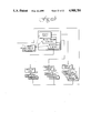
- FIG. 1 shows a conceptual line diagram of the operation of the present measurement apparatus.
- FIG. 2 comprised of waveforms A through F, shows a conceptual timing diagram of the development of the ramped START/STOP voltages from which the fine count intervals are determined.
- FIG. 3 shows an overall system block diagram
- FIG. 4 shows a block diagram of the time measurement interface circuitry.
- FIG. 5 shows a block diagram of the time measurement calibration circuitry.
- FIG. 6 shows a functional block diagram of the analog time measurement circuitry.
- FIG. 7 shows a detailed schematic diagram of the time measurement interface circuitry of FIG. 4.
- FIG. 8 shows a detailed schematic diagram of the time measurement circuitry.
- FIG. 10 shows a timing diagram of a typical measurement sequence.
- FIG. 11 shows a flow chart of the equipment's power-up and diagnostics.
- FIG. 12 shows a flow chart of the calibration/mode select operations and the display, trigger and gate group select operations.
- FIG. 1 a conceptual line diagram is shown of the methodology employed by the present invention to measure with picosecond precision either repetitive or non-repetitive events so long as the event exhibits a detectable edge condition.
- the invention divides the interval to be measured into three periods. These are a coarse count period and START and STOP fine count periods.
- the coarse count period is comprised of a whole integrated number of clock cycles produced by a precisely calibrated, synchronous, 100 MHz master clock signal.
- the fine count periods are fractional measures of one master clock cycle and are determined relative to time values stored within a calibrated fine count memory (FCM). That is, separate randomly derived START and STOP interval values are stored which are fitted to and exemplary of the ramped, straight line, time vs. charge characteristic exhibited by the START and STOP measurement circuitry of the invention.
- FCM calibrated fine count memory
- measurement of the fine count periods is achieved by charging individual capacitors in the START/STOP measurement circuitry from a regulated current source from the beginning of the separately detected asynchronous START/STOP events until the next leading edges of the cyclical master clock signal. With the occurrence of the clock signal, the attained analog capacitor voltage is converted to a digital form and used to compute the address for the corresponding time interval contained within the fine count memory. The T START and T STOP times are next added and subtracted from the course count which is obtained in conventional fashion by counting each complete clock cycle for the intervening period.
- the measurement of the foregoing fine and coarse count periods are achieved from measured analog event values which are converted to digital form and processed via a microprocessor having access to the FCM. Very precise measurements are assured through the calibration of the FCM relative to the same internal circuitry used to measure the measured events which are separately corrected for potential delays induced by the test fixture, including its coupling leads. The details of such calibrations, correction and measurement processes and apparatus will be described hereinafter.
- waveforms A through F depict in greater detail the operation of the circuitry relative to the foregoing conceptual operation. Specifically, the fine count and coarse count periods are shown relative to a typical asynchronous event demonstrated by the detected START and STOP edge events shown in waveforms C and E relative to the master clock and the determined fine and coarse count periods of waveforms A and B. Waveforms D and F, in turn, shows the operation of the invention during the fine count periods, which is the same for either the START or STOP periods.
- a regulated current supplied to a capacitor in associated START/STOP track and hold circuitry is interrupted, causing the capacitor to discharge from a clamped voltage near ground level to a voltage V bias and from which the capacitor is recharged until the occurrence of the next rising edge of the master clock.
- a rising or falling clock edge can be defined by the operator as the trigger for terminating the charge time.
- a straight line charging characteristic is achieved which over the range of a -2 volts to a +2 volts is defined to coincide with one master clock cycle or a period of 10 nanoseconds (NSEC).
- NSC nanoseconds
- each potential 10 NSEC clock cycle is subdivided into approximately 16,000 discrete intervals corresponding to measured voltages derived from some 200,000 samplings exhibited at the START/STOP ramp circuitry. Although larger samplings could be used, experience has shown the foregoing sample size to produce sufficient accuracy and redundancy in plotting the linear points to assure picosecond accuracy.
- the circuitry uses approximately 12,000 of these sample points to provide a resolution of approximately 0.825 picoseconds per sub-division and relative to which the measured event may be compared to determine its START/STOP times. That is, upon converting the measured analog voltage to a 14 bit digital value, that value is used to address the FCM whereat the corresponding, precalibrated time value is stored. In a similar fashion, ⁇ START and ⁇ STOP fine counts are determined for each measured event and respectively added and subtracted from the coarse count which is obtained in conventional fashion by maintaining a count of the intervening clock cycles.
- FIG. 3 a generalized block diagram is shown of the circuitry used by the present invention to achieve the foregoing results which is configured in a bench top/rack mountable chassis for use by itself or as part of a test system, where it may be operated under computer control.
- the CPU circuitry 2 includes an IEEE 488 interface through which a remote control connection can be made and used to configure and operate the circuitry during task operations.
- the CPU 2 comprises an Intel single card computer, model ISBC 286/10A. Associated materials describing the operation thereof may be obtained from the manufacturer. In addition to the IEEE-488 interface, it includes an 80286 processor, an 80287 coprocessor, a 9600 baud RS422 serial port and a multibus interface. Otherwise, the CPU board 2 also contains the fine count memory 4 which comprises four 32K RAM chips, two of which store START ramp data and the other two of which store STOP ramp data. The other available memory contains the microinstructions used to operate the CPU and associated circuitry in the fashion described herein and the operator programmed or remotely programmed operating parameters.
- the front panel permits the operator to select a number of operating conditions which are indicated by associated pilot lights on the panel. These are whether the circuitry is to be controlled remotely, in which event all other pilots are turned off; whether the master clock is powered; and one of four operating modes wherein the circuitry may be internally and externally calibrated, operated in a burst mode, pursuant to a separately entered sample size, or in a continuous mode.
- Associated manual, automatic and external trigger functions are also provided along with an ability to externally define START/STOP gate signals and relative to which measurements are taken. Additionally, the operator is able to establish a variety of computed values which may be displayed on a provided forty character LCD display.
- Power is supplied to the various circuitry by five isolated power supplies 6, 8 and 10 which supply the voltages shown by way of appropriate filter circuitry 12.
- two power switches are provided, one on the front of the operator panel and one on the rear.
- the rear panel switch serves as a manual bypass switch to assure the master clock is always on to avoid unnecessary warm up delays, even though the front panel power switch may be off. Upon shutting the rear panel switch off, power control may be delegated to the front panel switch.
- the circuitry is constructed around a bus architecture to enable the CPU 2 to interact with the measurement circuitry 14 and calibration circuitry 16 by way of the interface circuitry 18 and 20.
- the internal interface circuitry 20 operates to convert and properly couple ECL/TTL signals between the various circuitry.
- the external interface circuitry 18 couples the fiberoptic input event signals and external inputs between the front panel, CPU and measurement circuitry.
- the 100 MHz crystal oscillator 22 is precisely calibrated by the National Bureau of Standards to an accuracy of 1.0 ⁇ 10 -8 seconds.
- FIGS. 4, 5 and 6 generalized block diagrams are shown of the circuitry contained on printed circuit boards 14, 16 and 20. Corresponding detailed schematic diagrams of this circuitry are also respectively shown at FIGS. 7, FIG. 8 and FIGS. 9A-9F.
- the following description will proceed with respect to the generalized block diagrams of FIGS. 4, 5 and 6, with periodic mention, as necessary, to the corresponding detailed circuitry of FIGS. 7, 8 and 9.
- FIG. 4 a generalized block diagram is shown of the interface circuitry 20, the detailed schematic diagram of which can again be seen in FIG. 7. Generally, it operates as a logic level conversion board to convert the various transistor transistor logic (TTL) signals to emitter coupled logic (ECL) signals to interface the calibration 16 and measurement circuitry 14 to one another and to interface with CPU 2 and externally produced signals. These functions are generally designated by way of the dotted line segmentation shown.
- TTL transistor transistor logic
- ECL emitter coupled logic
- the ECL/TTL multiplexing and ECL/TTL conversion are achieved by way of the ECL multiplexer 30, ECL/TTL converter 32 and TTL multiplexer 34 which are coupled by way of the data output buffer 36 to the bussed interface 18 and CPU 2.
- the multiplexer 30 appropriately select the START/STOP ramp control signals which are converted and coupled to the measurement circuitry 14 by way of multiplexer 34. These signals define whether the first measured event was a START or STOP condition and when the START/STOP ramps are to be measured relative to the master clock. Otherwise, the 14 bits of TTL data corresponding to the measured voltages developed by the START and STOP ramp circuitry are separately coupled via multiplexer 34 and the output buffers 35 to the CPU 2. Coarse count data is separately coupled to the output buffers 35.
- TTL level control signals are coupled from the CPU 2 and front panel to the bus interface 36 and TTL/ECL converter 38 where four bits of operator entered internal control data are ECL level shifted via a number of NAND gates before being latched at the latch 40 and selected by way of multiplexer 30.
- control data are stored in the latch 40 which data bits define the selected mode of operation. These control bits determine the flow of measured data through the multiplexer 34 to the CPU 2.
- the interface circuitry 20 controls the transfer of data between the calibration and measurement circuitry 14 and 16 and to the CPU 2.
- ECL/TTL level logic circuitry is presently used, it is to be appreciated other circuit types at other levels may equally be used.
- FIG. 5 a block diagram is shown of the calibration circuitry and related control which couple pseudorandomly generated sample event signals to the measurement circuitry 14 whereat the START/STOP circuitry produces the 16,000 data points stored in the fine count memory 4.
- the CPU 2 first turns off the whomper circuitry 42 which is used during external calibration and which will be described hereinafter. With the operator's further definition of whether the START and STOP events are to be measured relative to a rising or falling clock edge via control signals 43, the START and STOP calibration gates 44 and 46 are clocked to enable the ramp generator circuitry of FIG. 6.
- the START/STOP counters 48 and 50 are next enabled by the CPU 2 and the front panel/calibration multiplexer 52 couples pseudorandomly produced START/STOP sample event signals produced thereby to the measurement circuitry. There the START/STOP track and hold conversion circuitry captures the sample magnitudes representative of the linear charge characteristics developed by the measurement circuitry for each sample, which magnitudes are clamped and coupled via the TTL multiplexer 34 to the CPU and FCM 4.
- ring counter 48 and binary counter 50 are started via relay coupled control signals (reference FIG. 8) and operate to successively produce 128 START and STOP events of random interval width and random spacing from one another.
- the counters repeat themselves every 256 cycles, but otherwise essentially operate in a pseudorandom or so-called "Monte Carlo" fashion.
- the track and hold and conversion circuitry in turn, produce multiple measured analog charge values for each value ultimately plotted into memory, which values are arranged and plotted into the FCM by the CPU 2. These calibrated values ultimately are used to determine the duration of unknown measured events by comparison thereto.
- some 200,000 START/STOP sample occurrences are thus generated and fitted to a linear ramp in some 90 seconds.
- This calibration need not be repeated either, except where environmental conditions may change and induce drift or intolerable error as reflected by changes in the displayed standard of deviation or range values.
- the calibration is easily performed by way of the measurement circuitry itself and thus any errors or inconsistencies which might otherwise occur between separate calibration and measurement circuits are overcome and discounted, since the present arrangement utilizes the identical circuitry for both operations.
- the whomper circuitry 42 is enabled. It operates to produce edge signals which are coupled to the test fixture, which typically comprises a test stand and associated coupling leads to the present time measurement apparatus. In two separate operations, the ends of the coupling leads from the test stand are connected between the external calibration output at the front panel and the START and STOP input jacks. During each calibration sequence, one hundred sample edge signals are coupled to the test fixture and the throughput time delays are measured and averaged for each sampling. The averaged values are then stored in memory, later to be factored into the internal computations of the measured events.
- the all signal path lengths are controlled to tolerances of 0.001 inches to assure that inconsistencies do not exist between the START/STOP channels which might result in accrued error, otherwise negated by the present internal/external calibration techniques.
- too calibration may be achieved in 90 seconds, a warm up or crystal stabilization time of 1/2 hour is recommended, consequently the mentioned use of separate power switches.
- calibration need only occur once, upon warm up, although the equipment may be recalibrated prior to any given measurement to minimize against inconsistent environmental conditions between the times of calibration and measurement.
- FIG. 8 essentially being replicas of the START and STOP conditions, provisions are made in the logic circuitry to separately determine which clock edge (i.e. rising or falling) is selected to turn on the ramp generator circuitry. Accordingly, the OR and XOR gates 53a,b and 54a,b of FIG. 8 control which edge is selected relative to the internal calibration clock or the external START input. Also provided are the pretrigger and re-synchronized trigger latches 55a,b and 56a,b which, depending upon the programmed trigger events, arm or clear the circuitry to capture successively following events. Otherwise, OR gates 57a,b determine which external START or STOP input is measured first relative to the selected trigger condition. Consequently, the internal or period between intervals may be measured.
- This circuitry generally controls the STARTING and STOPPING of each ramp generator (FIGS. 9C, D and E, F), the tracking and holding or clamping of the accumulated charge or voltage during each START/STOP interval (FIG. 9A), the analog to digital conversion of the ramp values and the measurement of the coarse count interval (FIG. 9B).
- the START event is coupled by way of the control circuitry 60 (reference also FIGS. 9C and D) to the START and STOP ramp generators 62 and 64 (reference also FIGS. 9E and F) which as previously mentioned and relative to the master clock are initiated upon the occurrence of the event to discharge their related capacitors and begin recharging these capacitors until the occurrence of the next rising or falling clock edge as specified by the operator.
- the control circuitry 60 reference also FIGS. 9C and D
- the START and STOP ramp generators 62 and 64 reference also FIGS. 9E and F
- the coarse counter 66 (reference FIG. 9B) is also enabled and begins to count each whole master clock cycle until the occurrence of the first clock signal subsequent to the STOP signal.
- the corresponding track and hold circuitry 68 With the selected first rising or falling clock edge and assuming a START event occurs first, the corresponding track and hold circuitry 68 is enabled to clamp the accumulated charge or voltage value which, in turn, is converted upon enabling the ECL/TTL generator 72 and 14 bit A/D converter 74 and stored in status register 78.
- the STOP value is obtained from track and hold circuitry 70 and A/D converter 74 and temporarily stored in status register 78 before being coupled via the interface circuitry 20 to the CPU 2.
- the coarse counter 66 data is also coupled to the CPU along with the control signals defining whether the STOP or START was the first occurring event. Depending too upon the duration of the measured event, if it exceeds approximately 2.5 seconds, an overflow signal may be produced and coupled to reset the circuitry; otherwise, the CPU per its microinstructions computes or stores the corresponding programmed values. Also and as each START/STOP event occurs, it is counted (see FIG. 9C) along with any pretrigger or overflow, and used to reset the circuitry prior to the next interval to be measured.
- the CPU board 2 includes pre-programmed ROM memory where microinstructions are stored for controlling the CPU board 2 during the foregoing operations.
- ROM memory where microinstructions are stored for controlling the CPU board 2 during the foregoing operations.
- the operator may alternatively test the condition of the front panel switches and lights by selecting "GO” selectively actuating each switch, while monitoring the condition of the associated pilot lights.
- the status of the FCM is determined and if not previously calibrated reverts to a self-enabled internal calibration sequence.
- the system confirms the calibrated status of the FCM, preparatory to taking measurements per the previously established operating conditions.
- the system reverts to a condition where it may be re-calibrated with the performance of separate external and internal calibrations or the mode may be set.
- the apparatus Upon enabling an internal calibration, the apparatus again pseudorandomly produces and averages START/STOP samples until all memory locations of the FCM are loaded. Otherwise an external calibration may be performed.
- the operator may select the operating mode which may either be a burst or continuous mode. Regardless which mode is selected, the number of events to be measured is also entered; in the burst mode, a single sampling of the set number of events thereafter occurs, and in the continuous mode, repetitive samplings are thereafter taken on a continuing basis until the mode is reprogrammed. If no mode is selected, the circuitry remains in a default, idle condition.
- the operator next selects the data to be displayed as per FIG. 12 which may comprise the average pulse width measured for the sample, the standard deviation of the sample, the minimum pulse width measured for the sample, the maximum pulse width measured, the range or difference between the minimum and maximum measurements, and set sample size.
- the data to be displayed as per FIG. 12 which may comprise the average pulse width measured for the sample, the standard deviation of the sample, the minimum pulse width measured for the sample, the maximum pulse width measured, the range or difference between the minimum and maximum measurements, and set sample size.
- a corresponding CPU subroutine performs the necessary processing.
- either a manual, automatic or external trigger may be selected.
- the selection of a trigger arms the circuitry to measure the next occurring rising or falling pulse edge.
- either of both of the START, STOP gate conditions may be selected and by which inputs from either or both of the START/STOP conductors at the face panel are separately measured.
Abstract
Description
Claims (25)
Priority Applications (2)
| Application Number | Priority Date | Filing Date | Title |
|---|---|---|---|
| US07/081,368 US4908784A (en) | 1987-08-04 | 1987-08-04 | Method and apparatus for asynchronous time measurement |
| PCT/US1988/002645 WO1989001191A1 (en) | 1987-08-04 | 1988-08-03 | Method and apparatus for asynchronous time measurement |
Applications Claiming Priority (1)
| Application Number | Priority Date | Filing Date | Title |
|---|---|---|---|
| US07/081,368 US4908784A (en) | 1987-08-04 | 1987-08-04 | Method and apparatus for asynchronous time measurement |
Publications (1)
| Publication Number | Publication Date |
|---|---|
| US4908784A true US4908784A (en) | 1990-03-13 |
Family
ID=22163711
Family Applications (1)
| Application Number | Title | Priority Date | Filing Date |
|---|---|---|---|
| US07/081,368 Expired - Lifetime US4908784A (en) | 1987-08-04 | 1987-08-04 | Method and apparatus for asynchronous time measurement |
Country Status (2)
| Country | Link |
|---|---|
| US (1) | US4908784A (en) |
| WO (1) | WO1989001191A1 (en) |
Cited By (42)
| Publication number | Priority date | Publication date | Assignee | Title |
|---|---|---|---|---|
| US5027298A (en) * | 1989-06-29 | 1991-06-25 | Genrad, Inc. | Low-dead-time interval timer |
| US5075878A (en) * | 1988-06-29 | 1991-12-24 | Kabushiki Kaisha Topcon | High resolution measuring device for time difference |
| US5113398A (en) * | 1989-06-01 | 1992-05-12 | Shackleton System Drives Corporation | Self-healing data network and network node controller |
| US5166959A (en) * | 1991-12-19 | 1992-11-24 | Hewlett-Packard Company | Picosecond event timer |
| US5333162A (en) * | 1993-02-23 | 1994-07-26 | The United States Of America As Represented By The United States Department Of Energy | High resolution time interval counter |
| USRE35296E (en) * | 1992-09-16 | 1996-07-16 | Honeywell Inc. | Full and partial cycle counting apparatus and method |
| US5625579A (en) * | 1994-05-10 | 1997-04-29 | International Business Machines Corporation | Stochastic simulation method for processes containing equilibrium steps |
| US5745385A (en) * | 1994-04-25 | 1998-04-28 | International Business Machines Corproation | Method for stochastic and deterministic timebase control in stochastic simulations |
| US5748017A (en) * | 1996-07-19 | 1998-05-05 | Texas Instruments Incorporated | Method and apparatus for determining linearity of a ramp signal |
| US5801560A (en) * | 1995-09-13 | 1998-09-01 | The United States Of America As Represented By The Secretary Of The Navy | System for determining time between events using a voltage ramp generator |
| US5805532A (en) * | 1996-08-29 | 1998-09-08 | Nec Corporation | Time interval measurement system and method applied therein |
| WO1998040693A2 (en) * | 1997-03-13 | 1998-09-17 | Wavecrest Corporation | Time interval measurement system incorporating a linear ramp generation circuit |
| US5826065A (en) * | 1997-01-13 | 1998-10-20 | International Business Machines Corporation | Software architecture for stochastic simulation of non-homogeneous systems |
| US5828717A (en) * | 1995-03-28 | 1998-10-27 | Matsushita Electric Industrial Co. Ltd. | Time counting circuit and counter circuit |
| US5835552A (en) * | 1995-11-13 | 1998-11-10 | Matsushita Electric Industrial Co.,Ltd. | Time counting circuit and counter circuit |
| US5872745A (en) * | 1997-06-20 | 1999-02-16 | Nec Corporation | Time measuring method and time measuring system which enable to discriminate whether or not the measurement result is within the required measurement |
| WO1999012166A1 (en) * | 1997-09-01 | 1999-03-11 | Ifunga Test Equipment B.V. | Method and device for measuring and registering statistical time variations for an optical data carrier |
| US6137283A (en) * | 1995-02-22 | 2000-10-24 | Michael K. Williams | Process and machine for signal waveform analysis |
| US6226344B1 (en) * | 1997-06-27 | 2001-05-01 | U.S. Philips Corporation | Generation of a time period |
| US6298315B1 (en) * | 1998-12-11 | 2001-10-02 | Wavecrest Corporation | Method and apparatus for analyzing measurements |
| US6369738B1 (en) | 1999-08-17 | 2002-04-09 | Eric Swanson | Time domain/frequency domain data converter with data ready feature |
| WO2002059699A2 (en) * | 2001-01-16 | 2002-08-01 | Wavecrest Corporation | Measurement system with a frequency-dividing edge counter |
| US6477117B1 (en) * | 2000-06-30 | 2002-11-05 | International Business Machines Corporation | Alarm interface for a smart watch |
| US20020181438A1 (en) * | 2001-05-16 | 2002-12-05 | Mcgibney Grant H. | Centralized synchronization for wireless networks |
| US6751641B1 (en) | 1999-08-17 | 2004-06-15 | Eric Swanson | Time domain data converter with output frequency domain conversion |
| US6813589B2 (en) | 2001-11-29 | 2004-11-02 | Wavecrest Corporation | Method and apparatus for determining system response characteristics |
| US6865496B2 (en) | 2001-11-01 | 2005-03-08 | Agilent Technologies, Inc. | Zero-crossing direction and time interval jitter measurement apparatus using offset sampling |
| EP1521143A1 (en) * | 2003-10-01 | 2005-04-06 | Acqiris | Time to Digital Converter |
| US20050286627A1 (en) * | 2004-06-28 | 2005-12-29 | Guide Technology | System and method of obtaining random jitter estimates from measured signal data |
| US20060047450A1 (en) * | 2004-08-31 | 2006-03-02 | Guide Technology | System and method of obtaining data-dependent jitter (DDJ) estimates from measured signal data |
| US20060100801A1 (en) * | 2004-11-09 | 2006-05-11 | Guide Technology | System and method of generating test signals with injected data-dependent jitter (DDJ) |
| US20080169826A1 (en) * | 2007-01-12 | 2008-07-17 | Microchip Technology Incorporated | Measuring a long time period or generating a time delayed event |
| US20090055111A1 (en) * | 2007-08-23 | 2009-02-26 | Amherst Systems Associates Corporation | Waveform anomoly detection and notification systems and methods |
| US20090132207A1 (en) * | 2007-11-07 | 2009-05-21 | Guidetech, Inc. | Fast Low Frequency Jitter Rejection Methodology |
| US20090154300A1 (en) * | 2007-12-14 | 2009-06-18 | Guide Technology, Inc. | High Resolution Time Interpolator |
| US20100141240A1 (en) * | 2008-12-08 | 2010-06-10 | Andrew Hutchinson | Methods for determining the frequency or period of a signal |
| US20100229053A1 (en) * | 2009-03-06 | 2010-09-09 | Advantest Corporation | Method and apparatus for time vernier calibration |
| US7941287B2 (en) | 2004-12-08 | 2011-05-10 | Sassan Tabatabaei | Periodic jitter (PJ) measurement methodology |
| CN103235502A (en) * | 2013-04-26 | 2013-08-07 | 东莞丝丽雅电子科技有限公司 | Timing device and system for performing automatic time check by using short-distance wireless communication interface |
| US8566655B2 (en) * | 2008-09-17 | 2013-10-22 | Robert Bosch Gmbh | Method for operating a communication system having a plurality of nodes, and a communication system therefor |
| EP2657713A1 (en) * | 2012-04-24 | 2013-10-30 | VEGA Grieshaber KG | Method and device for determining a measurement capacity |
| CN112650044A (en) * | 2020-12-24 | 2021-04-13 | 中国科学院精密测量科学与技术创新研究院 | High-precision time measuring device and method based on delay ring redundant state information |
Families Citing this family (2)
| Publication number | Priority date | Publication date | Assignee | Title |
|---|---|---|---|---|
| DE4222643A1 (en) * | 1992-07-10 | 1994-01-13 | Bodenseewerk Geraetetech | Device for measuring pulse transit times |
| DE69923160T2 (en) * | 1998-01-30 | 2005-12-29 | Wavecrest Corp., Edina | JITTER ANALYZER AND METHOD OF JITTER ANALYSIS |
Citations (11)
| Publication number | Priority date | Publication date | Assignee | Title |
|---|---|---|---|---|
| US3133189A (en) * | 1960-08-05 | 1964-05-12 | Hewlett Packard Co | Electronic interpolating counter for the time interval and frequency measurment |
| US4164648A (en) * | 1978-06-23 | 1979-08-14 | Hewlett-Packard Company | Double vernier time interval measurement using triggered phase-locked oscillators |
| US4165459A (en) * | 1978-01-16 | 1979-08-21 | Rca Corporation | Time interval measurement |
| US4303983A (en) * | 1978-09-29 | 1981-12-01 | Mitec-Moderne Industrietechnik Gmbh | Method and apparatus for measuring time |
| US4392749A (en) * | 1981-07-10 | 1983-07-12 | The United States Of America As Represented By The Administrator Of The National Aeronautics And Space Administration | Instrument for determining coincidence and elapse time between independent sources of random sequential events |
| US4516861A (en) * | 1983-10-07 | 1985-05-14 | Sperry Corporation | High resolution and high accuracy time interval generator |
| US4523288A (en) * | 1981-03-16 | 1985-06-11 | Takeda Riken Co., Ltd. | Interval-expanding timer |
| US4613950A (en) * | 1983-09-22 | 1986-09-23 | Tektronix, Inc. | Self-calibrating time interval meter |
| US4637733A (en) * | 1984-05-17 | 1987-01-20 | Commissariat A L'energie Atomique | High-resolution electronic chronometry system |
| US4678345A (en) * | 1986-05-01 | 1987-07-07 | Tektronix, Inc. | Equivalent time pseudorandom sampling system |
| US4764694A (en) * | 1987-04-22 | 1988-08-16 | Genrad, Inc. | Interpolating time-measurement apparatus |
Family Cites Families (1)
| Publication number | Priority date | Publication date | Assignee | Title |
|---|---|---|---|---|
| US4675345A (en) * | 1984-07-16 | 1987-06-23 | Penwalt Corporation | Foamable polyvinylidene fluoride and methods |
-
1987
- 1987-08-04 US US07/081,368 patent/US4908784A/en not_active Expired - Lifetime
-
1988
- 1988-08-03 WO PCT/US1988/002645 patent/WO1989001191A1/en unknown
Patent Citations (11)
| Publication number | Priority date | Publication date | Assignee | Title |
|---|---|---|---|---|
| US3133189A (en) * | 1960-08-05 | 1964-05-12 | Hewlett Packard Co | Electronic interpolating counter for the time interval and frequency measurment |
| US4165459A (en) * | 1978-01-16 | 1979-08-21 | Rca Corporation | Time interval measurement |
| US4164648A (en) * | 1978-06-23 | 1979-08-14 | Hewlett-Packard Company | Double vernier time interval measurement using triggered phase-locked oscillators |
| US4303983A (en) * | 1978-09-29 | 1981-12-01 | Mitec-Moderne Industrietechnik Gmbh | Method and apparatus for measuring time |
| US4523288A (en) * | 1981-03-16 | 1985-06-11 | Takeda Riken Co., Ltd. | Interval-expanding timer |
| US4392749A (en) * | 1981-07-10 | 1983-07-12 | The United States Of America As Represented By The Administrator Of The National Aeronautics And Space Administration | Instrument for determining coincidence and elapse time between independent sources of random sequential events |
| US4613950A (en) * | 1983-09-22 | 1986-09-23 | Tektronix, Inc. | Self-calibrating time interval meter |
| US4516861A (en) * | 1983-10-07 | 1985-05-14 | Sperry Corporation | High resolution and high accuracy time interval generator |
| US4637733A (en) * | 1984-05-17 | 1987-01-20 | Commissariat A L'energie Atomique | High-resolution electronic chronometry system |
| US4678345A (en) * | 1986-05-01 | 1987-07-07 | Tektronix, Inc. | Equivalent time pseudorandom sampling system |
| US4764694A (en) * | 1987-04-22 | 1988-08-16 | Genrad, Inc. | Interpolating time-measurement apparatus |
Non-Patent Citations (2)
| Title |
|---|
| Review of Scientific Instruments, Sep. 1968, "Digital Time Intervalometer", R. Nutt, pp. 1342-1345. |
| Review of Scientific Instruments, Sep. 1968, Digital Time Intervalometer , R. Nutt, pp. 1342 1345. * |
Cited By (82)
| Publication number | Priority date | Publication date | Assignee | Title |
|---|---|---|---|---|
| US5075878A (en) * | 1988-06-29 | 1991-12-24 | Kabushiki Kaisha Topcon | High resolution measuring device for time difference |
| US5113398A (en) * | 1989-06-01 | 1992-05-12 | Shackleton System Drives Corporation | Self-healing data network and network node controller |
| US5027298A (en) * | 1989-06-29 | 1991-06-25 | Genrad, Inc. | Low-dead-time interval timer |
| US5166959A (en) * | 1991-12-19 | 1992-11-24 | Hewlett-Packard Company | Picosecond event timer |
| USRE35296E (en) * | 1992-09-16 | 1996-07-16 | Honeywell Inc. | Full and partial cycle counting apparatus and method |
| US5333162A (en) * | 1993-02-23 | 1994-07-26 | The United States Of America As Represented By The United States Department Of Energy | High resolution time interval counter |
| US5745385A (en) * | 1994-04-25 | 1998-04-28 | International Business Machines Corproation | Method for stochastic and deterministic timebase control in stochastic simulations |
| US5625579A (en) * | 1994-05-10 | 1997-04-29 | International Business Machines Corporation | Stochastic simulation method for processes containing equilibrium steps |
| US6263290B1 (en) | 1995-02-22 | 2001-07-17 | Michael K. Williams | Process and machine for signal waveform analysis |
| US6529842B1 (en) | 1995-02-22 | 2003-03-04 | Michael K. Williams | Process and machine for signal waveform analysis |
| US6137283A (en) * | 1995-02-22 | 2000-10-24 | Michael K. Williams | Process and machine for signal waveform analysis |
| US5828717A (en) * | 1995-03-28 | 1998-10-27 | Matsushita Electric Industrial Co. Ltd. | Time counting circuit and counter circuit |
| US5801560A (en) * | 1995-09-13 | 1998-09-01 | The United States Of America As Represented By The Secretary Of The Navy | System for determining time between events using a voltage ramp generator |
| US5835552A (en) * | 1995-11-13 | 1998-11-10 | Matsushita Electric Industrial Co.,Ltd. | Time counting circuit and counter circuit |
| US5748017A (en) * | 1996-07-19 | 1998-05-05 | Texas Instruments Incorporated | Method and apparatus for determining linearity of a ramp signal |
| US5805532A (en) * | 1996-08-29 | 1998-09-08 | Nec Corporation | Time interval measurement system and method applied therein |
| US5826065A (en) * | 1997-01-13 | 1998-10-20 | International Business Machines Corporation | Software architecture for stochastic simulation of non-homogeneous systems |
| US6185509B1 (en) | 1997-03-13 | 2001-02-06 | Wavecrest Corporation | Analysis of noise in repetitive waveforms |
| WO1998040693A2 (en) * | 1997-03-13 | 1998-09-17 | Wavecrest Corporation | Time interval measurement system incorporating a linear ramp generation circuit |
| WO1998040693A3 (en) * | 1997-03-13 | 1999-03-11 | Wavecrest Corp | Time interval measurement system incorporating a linear ramp generation circuit |
| US6194925B1 (en) | 1997-03-13 | 2001-02-27 | Wavecrest Corporation | Time interval measurement system incorporating a linear ramp generation circuit |
| WO1998040755A1 (en) * | 1997-03-13 | 1998-09-17 | Wavecrest Corporation | Analysis of noise in repetitive waveforms |
| US6449570B1 (en) | 1997-03-13 | 2002-09-10 | Wavecrest Corporation | Analysis of noise in repetitive waveforms |
| US5872745A (en) * | 1997-06-20 | 1999-02-16 | Nec Corporation | Time measuring method and time measuring system which enable to discriminate whether or not the measurement result is within the required measurement |
| US6226344B1 (en) * | 1997-06-27 | 2001-05-01 | U.S. Philips Corporation | Generation of a time period |
| WO1999012166A1 (en) * | 1997-09-01 | 1999-03-11 | Ifunga Test Equipment B.V. | Method and device for measuring and registering statistical time variations for an optical data carrier |
| US6298315B1 (en) * | 1998-12-11 | 2001-10-02 | Wavecrest Corporation | Method and apparatus for analyzing measurements |
| US20050027477A1 (en) * | 1998-12-11 | 2005-02-03 | Wavecrest Corporation | Method and apparatus for analyzing measurements |
| US6799144B2 (en) * | 1998-12-11 | 2004-09-28 | Wavecrest Corporation | Method and apparatus for analyzing measurements |
| US6751641B1 (en) | 1999-08-17 | 2004-06-15 | Eric Swanson | Time domain data converter with output frequency domain conversion |
| US6751690B1 (en) | 1999-08-17 | 2004-06-15 | Eric Swanson | Data converter with statistical domain output |
| US20050021580A1 (en) * | 1999-08-17 | 2005-01-27 | Eric Swanson | Time domain data converter with output frequency domain conversion |
| US6369738B1 (en) | 1999-08-17 | 2002-04-09 | Eric Swanson | Time domain/frequency domain data converter with data ready feature |
| US6477117B1 (en) * | 2000-06-30 | 2002-11-05 | International Business Machines Corporation | Alarm interface for a smart watch |
| WO2002059699A3 (en) * | 2001-01-16 | 2002-12-12 | Wavecrest Corp | Measurement system with a frequency-dividing edge counter |
| WO2002059699A2 (en) * | 2001-01-16 | 2002-08-01 | Wavecrest Corporation | Measurement system with a frequency-dividing edge counter |
| US20020181438A1 (en) * | 2001-05-16 | 2002-12-05 | Mcgibney Grant H. | Centralized synchronization for wireless networks |
| US7324559B2 (en) | 2001-05-16 | 2008-01-29 | Mcgibney Grant H | Centralized synchronization for wireless networks |
| US6865496B2 (en) | 2001-11-01 | 2005-03-08 | Agilent Technologies, Inc. | Zero-crossing direction and time interval jitter measurement apparatus using offset sampling |
| US6813589B2 (en) | 2001-11-29 | 2004-11-02 | Wavecrest Corporation | Method and apparatus for determining system response characteristics |
| US20050122846A1 (en) * | 2003-10-01 | 2005-06-09 | Jean-Luc Bolli | Time converter |
| US7423937B2 (en) | 2003-10-01 | 2008-09-09 | Agilent Technologies, Inc. | Time converter |
| EP1521143A1 (en) * | 2003-10-01 | 2005-04-06 | Acqiris | Time to Digital Converter |
| US20050286627A1 (en) * | 2004-06-28 | 2005-12-29 | Guide Technology | System and method of obtaining random jitter estimates from measured signal data |
| US7512196B2 (en) * | 2004-06-28 | 2009-03-31 | Guidetech, Inc. | System and method of obtaining random jitter estimates from measured signal data |
| US20060047450A1 (en) * | 2004-08-31 | 2006-03-02 | Guide Technology | System and method of obtaining data-dependent jitter (DDJ) estimates from measured signal data |
| US7203610B2 (en) | 2004-08-31 | 2007-04-10 | Guide Technology, Inc. | System and method of obtaining data-dependent jitter (DDJ) estimates from measured signal data |
| US20060100801A1 (en) * | 2004-11-09 | 2006-05-11 | Guide Technology | System and method of generating test signals with injected data-dependent jitter (DDJ) |
| US7239969B2 (en) | 2004-11-09 | 2007-07-03 | Guide Technology, Inc. | System and method of generating test signals with injected data-dependent jitter (DDJ) |
| US7941287B2 (en) | 2004-12-08 | 2011-05-10 | Sassan Tabatabaei | Periodic jitter (PJ) measurement methodology |
| US8368408B2 (en) | 2007-01-12 | 2013-02-05 | Microchip Technology Incorporated | Measuring a time period |
| US8217664B2 (en) | 2007-01-12 | 2012-07-10 | Microchip Technology Incorporated | Generating a time delayed event |
| US7460441B2 (en) | 2007-01-12 | 2008-12-02 | Microchip Technology Incorporated | Measuring a long time period |
| CN103197154A (en) * | 2007-01-12 | 2013-07-10 | 密克罗奇普技术公司 | Integrated time and/or capacitance measurement system, method and apparatus |
| US20080204046A1 (en) * | 2007-01-12 | 2008-08-28 | Microchip Technology Incorporated | Capacitance Measurement Apparatus and Method |
| CN101578526B (en) * | 2007-01-12 | 2013-03-27 | 密克罗奇普技术公司 | Integrated time and/or capacitance measurement system, method and apparatus |
| US20080169826A1 (en) * | 2007-01-12 | 2008-07-17 | Microchip Technology Incorporated | Measuring a long time period or generating a time delayed event |
| US8022714B2 (en) | 2007-01-12 | 2011-09-20 | Microchip Technology Incorporated | Capacitance measurement apparatus |
| WO2008088986A3 (en) * | 2007-01-12 | 2008-09-04 | Microchip Tech Inc | Integrated time and/or capacitance measurement system, method and apparatus |
| CN103197154B (en) * | 2007-01-12 | 2016-05-25 | 密克罗奇普技术公司 | The time of integration and/or capacitance measurement system, method and apparatus |
| KR101390274B1 (en) * | 2007-01-12 | 2014-04-30 | 마이크로칩 테크놀로지 인코포레이티드 | Integrated time and/or capacitance measurement system, method and apparatus |
| US20110178767A1 (en) * | 2007-01-12 | 2011-07-21 | Microchip Technology Incorporated | Measuring a time period |
| WO2008088986A2 (en) * | 2007-01-12 | 2008-07-24 | Microchip Technology Incorporated | Integrated time and/or capacitance measurement system, method and apparatus |
| US20110175659A1 (en) * | 2007-01-12 | 2011-07-21 | Microchip Technology Incorporated | Generating a time delayed event |
| US8024140B2 (en) | 2007-08-23 | 2011-09-20 | Amherst Systems Associates, Inc. | Waveform anomoly detection and notification systems and methods |
| US20090055111A1 (en) * | 2007-08-23 | 2009-02-26 | Amherst Systems Associates Corporation | Waveform anomoly detection and notification systems and methods |
| US8255188B2 (en) | 2007-11-07 | 2012-08-28 | Guidetech, Inc. | Fast low frequency jitter rejection methodology |
| US20090132207A1 (en) * | 2007-11-07 | 2009-05-21 | Guidetech, Inc. | Fast Low Frequency Jitter Rejection Methodology |
| US20110040509A1 (en) * | 2007-12-14 | 2011-02-17 | Guide Technology, Inc. | High Resolution Time Interpolator |
| US7843771B2 (en) * | 2007-12-14 | 2010-11-30 | Guide Technology, Inc. | High resolution time interpolator |
| US8064293B2 (en) | 2007-12-14 | 2011-11-22 | Sassan Tabatabaei | High resolution time interpolator |
| US20090154300A1 (en) * | 2007-12-14 | 2009-06-18 | Guide Technology, Inc. | High Resolution Time Interpolator |
| US8566655B2 (en) * | 2008-09-17 | 2013-10-22 | Robert Bosch Gmbh | Method for operating a communication system having a plurality of nodes, and a communication system therefor |
| US20100141240A1 (en) * | 2008-12-08 | 2010-06-10 | Andrew Hutchinson | Methods for determining the frequency or period of a signal |
| US8422340B2 (en) * | 2008-12-08 | 2013-04-16 | General Electric Company | Methods for determining the frequency or period of a signal |
| US20100229053A1 (en) * | 2009-03-06 | 2010-09-09 | Advantest Corporation | Method and apparatus for time vernier calibration |
| US7996168B2 (en) | 2009-03-06 | 2011-08-09 | Advantest Corporation | Method and apparatus for time vernier calibration |
| WO2010100955A1 (en) | 2009-03-06 | 2010-09-10 | Advantest Corporation | Method and apparatus for time vernier calibration |
| EP2657713A1 (en) * | 2012-04-24 | 2013-10-30 | VEGA Grieshaber KG | Method and device for determining a measurement capacity |
| CN103235502A (en) * | 2013-04-26 | 2013-08-07 | 东莞丝丽雅电子科技有限公司 | Timing device and system for performing automatic time check by using short-distance wireless communication interface |
| CN103235502B (en) * | 2013-04-26 | 2015-12-09 | 东莞丝丽雅电子科技有限公司 | Time set when utilizing short-range wireless communications interfaces to carry out automatic pair and system |
| CN112650044A (en) * | 2020-12-24 | 2021-04-13 | 中国科学院精密测量科学与技术创新研究院 | High-precision time measuring device and method based on delay ring redundant state information |
Also Published As
| Publication number | Publication date |
|---|---|
| WO1989001191A1 (en) | 1989-02-09 |
Similar Documents
| Publication | Publication Date | Title |
|---|---|---|
| US4908784A (en) | Method and apparatus for asynchronous time measurement | |
| US4975636A (en) | Method and apparatus for selecting and displaying a high resolution window from a main display | |
| KR100724115B1 (en) | Ate timing measurement unit and method | |
| US4150432A (en) | Frequency counter and method | |
| US6668346B1 (en) | Digital process monitor | |
| US6807243B2 (en) | Delay clock generating apparatus and delay time measuring apparatus | |
| US6285963B1 (en) | Measuring signals in a tester system | |
| WO2006004829A2 (en) | Precise time measurement apparatus and method | |
| US4613950A (en) | Self-calibrating time interval meter | |
| US5886660A (en) | Time-to-digital converter using time stamp extrapolation | |
| US4603292A (en) | Frequency and time measurement circuit | |
| US4350953A (en) | Time interval measurement apparatus | |
| US6784819B2 (en) | Measuring skew between digitizer channels using fourier transform | |
| US4736351A (en) | Precision semiconductor device timer | |
| EP0740234B1 (en) | Delta-T measurement circuit | |
| US4168467A (en) | Measurement of pulse duration | |
| US20120197570A1 (en) | Measurement of Parameters Within an Integrated Circuit Chip Using a Nano-Probe | |
| US6944099B1 (en) | Precise time period measurement | |
| EP0854355A1 (en) | Liquid level gauge interface system having dynamic offset | |
| JP3552123B2 (en) | Time measuring device and distance measuring device | |
| US4527907A (en) | Method and apparatus for measuring the settling time of an analog signal | |
| US20030220758A1 (en) | Method for testing an AD-converter | |
| JP3080480B2 (en) | Signal delay time measuring device | |
| US4999573A (en) | Method and apparatus for measurement gate display | |
| JPH05273245A (en) | Metastable state detection device |
Legal Events
| Date | Code | Title | Description |
|---|---|---|---|
| AS | Assignment |
Owner name: WAVE TECHNOLOGIES CORPORATION, 7351 WASHINGTON AVE Free format text: ASSIGNMENT OF ASSIGNORS INTEREST.;ASSIGNORS:BOX, GARY W.;FOOTE-LENNOX, THOMAS S.;HERREID, RODNEY G.;AND OTHERS;REEL/FRAME:004876/0049 Effective date: 19870803 Owner name: WAVE TECHNOLOGIES CORPORATION, A CORP. OF MINNESOT Free format text: ASSIGNMENT OF ASSIGNORS INTEREST;ASSIGNORS:BOX, GARY W.;FOOTE-LENNOX, THOMAS S.;HERREID, RODNEY G.;AND OTHERS;REEL/FRAME:004876/0049 Effective date: 19870803 |
|
| STCF | Information on status: patent grant |
Free format text: PATENTED CASE |
|
| CC | Certificate of correction | ||
| FPAY | Fee payment |
Year of fee payment: 4 |
|
| FEPP | Fee payment procedure |
Free format text: PAYOR NUMBER ASSIGNED (ORIGINAL EVENT CODE: ASPN); ENTITY STATUS OF PATENT OWNER: LARGE ENTITY |
|
| FPAY | Fee payment |
Year of fee payment: 8 |
|
| AS | Assignment |
Owner name: U.S. BANK NATIONAL ASSOCIATION, MINNESOTA Free format text: SECURITY AGREEMENT;ASSIGNOR:WAVECREST CORPORATION;REEL/FRAME:010485/0061 Effective date: 19991228 |
|
| FEPP | Fee payment procedure |
Free format text: PAT HLDR NO LONGER CLAIMS SMALL ENT STAT AS SMALL BUSINESS (ORIGINAL EVENT CODE: LSM2); ENTITY STATUS OF PATENT OWNER: LARGE ENTITY |
|
| FPAY | Fee payment |
Year of fee payment: 12 |
|
| AS | Assignment |
Owner name: J. STEPHEN SCHMIDT, MINNESOTA Free format text: TRANSFER OF SECURITY INTEREST;ASSIGNOR:U.S. BANK NATIONAL ASSOCIATION;REEL/FRAME:013813/0157 Effective date: 20030206 |