US4911149A - Vibratory treatment method and apparatus - Google Patents
Vibratory treatment method and apparatus Download PDFInfo
- Publication number
- US4911149A US4911149A US07/241,522 US24152288A US4911149A US 4911149 A US4911149 A US 4911149A US 24152288 A US24152288 A US 24152288A US 4911149 A US4911149 A US 4911149A
- Authority
- US
- United States
- Prior art keywords
- probe
- body cavity
- actuating
- urethra
- predetermined frequency
- Prior art date
- Legal status (The legal status is an assumption and is not a legal conclusion. Google has not performed a legal analysis and makes no representation as to the accuracy of the status listed.)
- Expired - Fee Related
Links
Images


Classifications
-
- A—HUMAN NECESSITIES
- A61—MEDICAL OR VETERINARY SCIENCE; HYGIENE
- A61H—PHYSICAL THERAPY APPARATUS, e.g. DEVICES FOR LOCATING OR STIMULATING REFLEX POINTS IN THE BODY; ARTIFICIAL RESPIRATION; MASSAGE; BATHING DEVICES FOR SPECIAL THERAPEUTIC OR HYGIENIC PURPOSES OR SPECIFIC PARTS OF THE BODY
- A61H21/00—Massage devices for cavities of the body, e.g. nose, ears and anus ; Vibration or percussion related aspects A61H23/00
Definitions
- Vibration applied to tissue increases blood circulation due to the increase in capillary dilation.
- the increased blood flow increases the consumption of oxygen and nutrients by muscles and improves the regeneration process.
- the result is an improved muscular tone, elasticity and contractile capacity.
- vibratory stimulation reduces tissue swelling, enhances healing of wounds and results in effective anti-inflamatory action.
- low frequency vibratory stimulation varies depending on the frequency, amplitude and duration of its application. Depending on the structure of the muscles (smooth or straiated), the same dose of local vibratory stimulation may cause either contraction or relaxation.
- a low frequency mechanical vibration of between 60 and 200 Hz applied to skeletal muscle induces a sustained contraction of the muscle and a simultaneous relaxation of its prime antagonists.
- This tonic vibratory reflex (TVR) is elicited in normal, spastic, paretic and myotonic muscles alike. Within the 60 to 200 Hz range, the vibration reduces the contractile force and tension of smooth muscle.
- Vibratory stimulation is used for treating neuromuscular motor dysfunction in patients with cerebral palsy.
- External vibration is also used for treating patients with cervical osteochondrosis, lumbosacral radiculitis, postamputation contracture, sequelae of lesions of the long tubular bones, and chronic dental pain.
- Externally applied abdominal vibration is used for improving efficiency in peritoneal dialysis and for stimulating intestinal mobility in cases of intestinal atonia.
- External vibratory stimulation is also useful for bladder voiding in paralyzed patients.
- Vibratory stimulation has also been used internally to relax and dilate the cervix prior to abortion or birth. Vibration accelerates expansion of the cervical opening, thereby facilitating parturition. The vibration is applied directly to the cervical muscle, and the source of the vibration is withdrawn as soon as the cervical dilation is achieved.
- Vibration sources vary with the application. External vibration may be applied by large flat or rounded vibrating machines designed to be placed against the appropriate body parts. Internal vibratory stimulation of the cervix, on the other hand, may be applied by a vibrating spatula or a vibrating bullet shaped applicator placed against the wall of the cervical muscle.
- Urethral strictures especially posttraumatic ones, are very dense, rigid, and resistant to stretching. They are localized mostly in the membranous or bulbous parts of the urethra.
- Such probes are known as bougies.
- Conventional bougies are shown in the text "Urology", 3d ed., v.1, p. 242, M. F. Campbell and J. H. Harrison, eds. (Saunders, 1970).
- Such bougies are solid metal or plastic rods which are shaped to accommodate the physiological curvature of the urethra.
- the urethra's outer part is within the highly flexible pendulus of the penis and can be bent or straightened as necessary.
- the urethra's inner part extends around the pubic articulation and is therefore curved.
- conventional bougies generally comprise a straight portion extending from the handle, followed by a curved portion adjacent the tip. This shape corresponds to the urethra when the penis is straightened.
- Urinary incontinence is a distressing and previously neglected condition which can result from a range of pathological processes in the central or peripheral nervous system, the bladder, or the urethra.
- the disorder is related to faulty storage or deficient control and is difficult to treat.
- Stress urinary incontinence is defined as the involuntary loss of urine through the intact urethra as the result of a sudden increase in intra-abdominal pressure in the absence of bladder activity. Stress urinary incontinence accounts for roughly 75% of all female urinary incontinence.
- the most frequent cause of stress urinary incontinence in females is the poor function of the sphincteric mechanism of the urethra and an inadequate pelvic floor function.
- the key factor in the development of stress incontinence in females is an inherent weakness in the mechanism of urinary continence upon which precipitating factors exert influence.
- the problem occurs in women in whom childbirth causes long-term anatomic damage and a relaxation in the pelvic and periurethral musculature. The percentage of such women comprises about 52.2% of the total number of stress urinary incontinence sufferers.
- Menopause is another very important precipitating factor in the development of stress incontinence.
- Hormonal dysfunction in postmenopausal women is characterized by estrogen deficiency and leads to atrophy of pelvic tissues. This can distort local anatomy and result in stress incontinence.
- Involuntary detrusor contractions are also a common cause of urinary frequency, urgency, nocturia, bed wetting, urge incontinence, and the like. Abnormalities of detrusor contraction may be of myogenic, neurogenic, or psychoplogic origin. In the absence of a neurologic lesion, the condition is termed "detrusor instability.”
- the unstable bladder is a very common problem affecting as much as 10% of the population and a substantially higher percentage at the two extremes of life. In most cases the etiology of the detrusor instability remains unknown, since these patients are referred to as having "idiopathic" detrusor instability. As a result, the treatment of detrusor instability is difficult.
- the surgical method is generally accepted as the most appropriate treatment for severe female genuine stress incontinence. In a number of cases, this method is also used for treating patients with a mild-to-moderate form of incontinence.
- New surgical techniques such as electronic stimulation of sphincters and implantations of artificial sphincters are widely used for treating patients with urinary incontinence caused by surgical traumas or by organic neurologic dysfunctions. Although these new methods give promising results, they still require further clinical studies as well as improvements in devices necessary for implementation of these methods.
- Drugs of several types also have been recommended for treating stress urinary incontinence. These drugs are nonspecific, however, and therefore act on structures and viscera other than the bladder and urethra. Large doses are often required, and toxicity can easily be reached before the desired effect on the bladder and urethra is achieved. Moreover, even when drug treatment is effective, it does not lead to restoration of a normal micturition pattern.
- Re-education for incontinence includes bladder retraining programs and re-education of the pelvic floor muscles.
- the bladder re-training method consists of instituting a program of scheduled voidings with a progressive increase in the interval between each micturition. A four to six week treatment program is common.
- Two different methods of electrical stimulation for the correction of urinary incontinence are in use and are classified according to the time of application and the intensity of electrical stimuli: long-term, or chronic, electrical stimulation and short-term, or maximum, electrical stimulation.
- Long-term electrical stimulation is continued 6-20 hours daily for prolonged periods of from 3 to 36 months and short-term, or maximum, electrical stimulation is continued 20-30 minutes over a one-month period, the stimulation being applied 1-5 times a day.
- Electrostimulation has been found to be valuable in cases of urinary urge incontinence due to detrusor instability since it is more effective than drug treatment and can produce re-education of incontinence. The mechanisms behind this curative effect are not yet defined, however.
- Exercise therapy which is a natural biological and non-invasive functional method of treatment, plays a leading role in non-surgical methods of treatment of stress urinary incontinence, as this method positively effects a weakened muscular-ligamentous apparatus of the pelvic floor.
- the exercise is designed to strengthen the urethral and periurethral striated muscles.
- Physiotherapy consists of four or five pelvic floor contractions repeated every hour and interrupted micturition practiced on each occasion. In the beginning, the treatment is carried out on a hospital basis for four weeks followed by self-treatment for a prolonged period of time.
- Urethral syndrome is a condition indicating lower urinary tract symptoms, such as frequency and dysuria in the absence of obvious bladder or urethral abnormality where the urine is sterile or contains less than 10 5 microorganisms per mL. Urethral syndrome has been estimated to occur in 20-30% of all adult females.
- urethral syndrome is extra-urethral pathology which is revealed in the form of changes in connective tissues between the urethra and the vagina (the urethrovaginal septum). This is expressed in an increased amount of collagenous tissue in the abovementioned area which, in turn, may lead to obstruction.
- vaginitis can produce dysuria and frequency by contingous involvement of the periurethral area.
- Treatment modalities range from an operative technique to a local application of silver nitrate, antibiotics, estrogens and steriods, as well as psychotherapy.
- Urethral dilation and manual massage has been recommended as treatment for urethral syndrome.
- Such treatment is typically performed with a rigid surgical instrument on which intravaginal massage of the urethral wall can be performed.
- hypoestrogenism occurs and retrogressive (senile) changes take place in the vaginal and urethral mucosa.
- the treatment of urethral syndrome secondary to hypoestrogenism is oral and topical vaginal estrogen.
- the main object of this invention is to provide an apparatus and method for the vibratory treatment of internal muscle and connective tissue disorders.
- Our invention is a method and apparatus for treating internal muscle and connective tissue disorders using vibratory stimulation and massage.
- an instrument having a probe and an actuator is inserted into a body cavity.
- the probe has a plurality of flexible elements which are bound together at one end.
- the probe is attached to a reciprocal actuator at the unbound end of the flexible elements.
- the actuator is activated to cause the probe to vibrate by expanding and contracting, thus massaging and stimulating the tissue adjacent the body cavity.
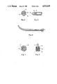
- FIG. 1 is a partial section view of a mechanically-driven bougie.
- FIG. 2 is a general view of the bougie of FIG. 1.
- FIG. 3 is a view of a probe of the bougie of FIG. 1.
- FIG. 4 is a cross-sectional view along lines 4--4 of FIG. 1.
- FIG. 5 is an enlarged view of element B of FIG. 2.
- FIG. 6 is a working portion of the bougie of FIG. 1 in an expanded position.
- FIG. 7 is a cross-sectional view along lines 7--7 of FIG. 1.
- FIG. 8 is a cross-sectional view along lines 8--8 of FIG. 1.
- FIG. 9 is a side view of a bougie according to a second embodiment of the invention.
- FIG. 10 is a longitudinal partially-broken view of a bougie according to a third embodiment of the invention.
- FIG. 11 is a view taken from the right side of FIG. 10.
- FIG. 12 is a view of a bougie according to a fourth embodiment of the invention.
- FIG. 13 is a cross-sectional view along lines 12--12 of FIG. 12.
- FIG. 14 shows a cross-sectional view of a bougie according to a fifth embodiment of the invention.
- FIG. 15 shows a cross-sectional view taken along the line 15--15 of FIG. 14.
- FIG. 16 shows a cross-sectional view taken along the line 16--16 of FIG. 14.
- FIG. 17 shows a partial sectional view of the bougie of FIG. 14 in an expanded condition.
- FIG. 18 shows a longitudinal sectional view of a bougie according to a sixth embodiment of the invention.
- FIG. 18a is a partial top view of the bougie of FIG. 18 showing the position of a pointer with respect to the scale.
- FIG. 19 is a cross-sectional view along the lines 19--19 in FIG. 18.
- FIG. 20 is a cross-sectional view along the lines 20--20 in FIG. 18.
- FIG. 21 is a cross-sectional view along the lines 21--21 in FIG. 18.
- FIG. 22 is a side partially-sectional view of the bougie of FIG. 18.
- FIG. 23 is a top view of the part of the bougie shown in FIG. 22.
- FIG. 1- Mechanically-Expandable Bougie
- the bougie according to a first embodiment consists generally of two main units, i.e., a drive unit 20 and a probe 22 which is attached to drive unit 20 in a manner described in detail below.
- Drive unit 20 may be a conventional commercially available device, such as a drive unit for an electric knife with two blades which reciprocate in opposite directions.
- Unit 20 includes a housing 24 with an electric motor (not shown) and a supply cord (not shown) for connection to a conventional electric power source (not shown), preferably a storage battery, to prevent electric injuries in case of a short circuit and patient grounding.
- a conventional electric power source not shown
- the rotational speed of the motor may be adjusted, e.g., by means of a sliding knob 27 which controls a speed control (not shown).
- Unit 20 has two output sliders 54 and 56 which protrude from a tubular output end 58 of housing 24 (FIG. 7). When the instrument is operated, sliders 54 and 56 reciprocate in opposite directions, their speed being controlled by knob 27. Housing 20 may also include stroke-length adjustment means (not shown). The sliders have recesses 60 and 62, respectively (FIG. 1), for receiving the shank portions of probe 22.
- Probe 22 the insertable part of the bougie, consists of two flexible, tapering rods 64 and 66 of semicircular cross sections (FIG. 4).
- Shank portions 68 and 70 of probe 22 are thicker and more rigid and have rectangular cross sections, as shown in FIG. 8, so as to be accommodated in rectangular recesses 60 and 62 of sliders 54 and 56, respectively.
- rods 64 and 66 are made of stainless steel and are about 30 mm long and 4.5 mm in diameter.
- rods 64 and 66 are pivotally connected to each other by a pivot pin 66'.
- FIG. 5 which is an enlargement of area B of FIG. 2
- either rod 64 or rod 66 has a fork-shaped end with a slot 72.
- a protruding portion 74 of the complementary rod is inserted into this slot so that both rods 64 and 66 can be pivotally interconnected by a pin 66'.
- rods 64 and 66 form a complete circle when seen in cross section, except for chamfered or rounded edges at opposite sides on mating surfaces 78 and 80. These rounded edges prevent pinching of mucosa during operation of the tool.
- the front end of probe 22 is also rounded.
- the probe in its working or folded state, corresponds in its shape to a conventional bougie. However, it is made smaller in diameter than a conventional bougie because it has a capacity to expand, as explained below. In fact, it corresponds in size to the smallest bougie of a conventional set and thus can be easily inserted into the urethra.
- the urethra can act inside the urethra more efficiently than the largest diameter bougie in a conventional set due to its ability to provide vibrational and massaging effects to strictures and their surrounding tissue. Also, as with a conventional bougie, it has a diameter which gradually narrows and flattens towards the tip so as to facilitate insertion.
- rods 64 and 66 In its rectangular shank portions 68 and 70, rods 64 and 66 have threaded holes 82 and 84 (FIG. 3). Screws 86 and 88 are threaded through holes 82 and 84 and mate with corresponding holes 90 and 92 in the protruding portions of sliders 54 and 56. These screws and holes are used for attachment of rods 64 and 66 to their respective sliders. In recesses 60 and 62 of the sliders, stop surfaces 94 and 90 are provided. The ends of shank portions 68 and 70 rest against these stops in order to align threaded holes 82 and 84.
- Probe 22 can be made of any suitable material which is durable, flexible, and hygienically acceptable for sterilization and insertion into the urethra.
- it can be made of stainless steel or plastic, such as polycarbonate, PFTE, etc.
- Probe 22 is folded and is attached to drive unit 20 by means of screws 86 and 88.
- shank portions 68 and 70 are pressed against stop surfaces 94 and 96 of respective sliders 54 and 56, whereupon threaded holes 82 and 84 will be aligned with holes 90 and 92 of the sliders.
- Each shank is attached to its corresponding slider by screws 86 and 88, respectively.
- a special gel for lubrication and anesthesia is introduced into the bladder.
- the bladder is filled with 150 ml. of sterile saline.
- Probe 22 is inserted into the urethra of the patient in the usual manner with the motor of drive unit 20 still off. This procedure is made less painful and less dangerous because of the smaller diameter of bougie 22.
- the force will tend to shorten the upper rod, which will remain straight.
- the lower rod being fixed at its distal tip by reason of its connection to the upper rod and being pushed out from its proximal end, will tend to lengthen and thus will bow out at its most flexible free part, i.e., near its tip.
- lower rod 66 will be pulled back and upper rod 64 pushed out, causing both rods to straighten, and then causing the lower rod to bow and the upper rod to straighten (not shown), and so on.
- the frequency is selected according to the type of treatment being given to the patient (dilatation of the stricture, massage of the urethra, massage of the neck of the bladder, etc.), but usually it should be within the limits of from 5 to 60 Hz, preferably, from 10 to 30 Hz.
- the duration of treatment also can vary, depending on many factors, such as the type of disease, condition of the patient, etc.
- the motor When the procedure is over, the motor is turned off and probe 22 is extracted from the urethra. After extraction, the actuating tool is disconnected from drive unit 20, sterilized, and is ready for reuse. Treatment should be repeated daily for four to six weeks.
- bougies are possible.
- only one of the rods of the actuating unit may be movable.
- Cam or eccentric-type mechanisms can be used instead of the crank mechanism shown in the illustrated embodiments.
- the bougie can be made of materials other than plastic or stainless steel, and the cams can be located in the vicinity of the tip or in any other place on the rods.
- the bougie has been discussed for use in urological applications, it and other probe-like instruments can be used in many other applications, including animals or inanimate objects, where an expandable probe is desired.
- the bougie can be used for vascular dilation in cranial, cardiac, and extremity applications. Also, it can be employed in any conduit or duct in mechanical, plumbing, and laboratory applications and the like where constriction, stenosis, or wall fusion of any lumen is encountered.
- FIG. 9 --Bougie with Overriding Cams
- urethral constrictions may have a considerable length.
- the tool of FIG. 9, which uses overriding cams, is most suitable.
- the mechanically-driven tool of this embodiment has the same drive unit 20 as used in the embodiment of FIGS. 1 and 2 and differs only in its probe 100.
- Probe 100 has two rods 108 and 110. At its proximal part, remote from tip 102, mutually engaging cams 104 and 106 are formed on the mating surfaces of rods 108 and 110.
- rods 108 and 110 reciprocate in mutually opposite directions. This causes cam 104 of rod 108 to override cam 106 of rod 110, causing the rods to separate and expand in the vicinity of the tip portion and in the region of cams 106 and 104. Thus, a longer portion of the probe expands and contracts, enabling a longer portion of the urethra to be treated.
- the insertion, control, and extraction of the tool are carried out in the same manner as has been described for the first embodiment of the invention.
- FIGS. 10 and 11 Manually-Rotatable Bougie with Wedges
- FIG. 10 is a longitudinal, partially-broken-away view of a probe 130.
- probe 130 consists of a pair of pivotally interconnected rods 132 and 134 of a semicircular cross section which together form a complete circle.
- Recesses 136 and 136' are formed in the respective rods 132 and 134, respectively. In an assembled state, these recesses form closed cavities which accommodate cams or wedges 138 and 138', respectively.
- Wedges 138 and 138' are attached to a rigid core or rod 140 which passes through a smaller diameter recess 142 formed between rods 132 and 134.
- the rear end of core 140 protrudes outside probe 130.
- the rear ends of rods 132 and 134 have grooves 144 and 146 which cooperate to form a complete thread when the bougie is assembled.
- a nut 148 is screwed onto this thread in order to fix the proximal end of the bougie and at the same time to provide a handle for a urologist who uses the bougie.
- the shape of this handle is shown in FIG. 11, a view taken from the right side in FIG. 10.
- the protruding end of core 140 is threaded at 150 so that it can mate with the inner thread in the hole 152 of nut 148 through which core 140 protrudes.
- the rear end of core 140 has a handle 154 rigidly attached thereto, e.g., by a bolt 156.
- bougie 130 is inserted into the urethra in a conventional manner and then is expanded mechanically by rotating handle 154 in the direction which provides forward movement of wedges 138 and 138'. In the course of its forward movement, the wedges will cause rods 132 and 134 to move apart, thereby increasing the diameter of the probe.
- Handle 154 is repeatedly rotated in forward and reverse directions of periodically expanding and constricting the probe, thereby to impart a massaging action to the surrounding tissue of the urethra.
- FIGS. 12 and 13 Manually-Operable Bougie with Rotatable Cams
- FIGS. 12 and 13 illustrate a fourth embodiment of a bougie of the invention.
- This embodiment is generally similar to the embodiment shown in FIGS. 10 and 11, but differs in that a rotatable cam or eccentric element 158 is attached to a core 160 instead of reciprocating wedges 138 and 138'.
- cams 158 will rotate, causing semicircular rods 162 and 164 to expand, periodically assuming the positions shown by the broken lines in FIG. 13.
- FIGS. 14-17 An embodiment of a mechanically-expandable bougie having a protruding wedge is shown in FIGS. 14-17.
- FIG. 14 is a longitudinal sectional view of a bougie 200. It consists of a pair of rods 202 and 204 pivotally connected at their front ends by a pivot pin 206.
- both rods have a semicircular cross sections so that in an assembled state of the bougie, they form a complete circle.
- Longitudinal grooves 208 and 210 are formed on mating inner surfaces 212 and 214 (FIG. 17) of the rods.
- Aligned holes 216 and 218 are formed in the front portion of the bougie, i.e., at a distance from 1/8 to 1/3 of the length of the rods from the point of their pivotal interconnection. These holes extend from the bottoms of respective grooves 208 and 210 to the peripheries of the respective rods.
- Grooves 208 and 210 are shallower adjacent the front end of the bougie, ahead of holes 216 and 218, than they are behind these holes.
- rod 202 The rear end of rod 202 is threaded at 220.
- the other rod, 204 is not threaded at its rear end 222, but rather has a smaller diameter than the inner diameter of threads 220.
- a shoulder 224 is formed between smaller diameter portion 222 and larger diameter portion 225 of rod 204.
- Rods 202 and 204 sandwich a longitudinal core element 226 in the guide slot formed by grooves 208 and 210.
- Core element 226 can slide freely in this slot.
- This core element has a flat (two-sided) wedge portion 228 on its front end.
- Wedge portion 228 has opposing lobes 230 and 232.
- the width of wedge portion 228 exceeds the diameter of the rods in their assembled state.
- the height of these protruding portions is preferably between 0.06 to 1.20 mm.
- the rear end of core element 226 has an annular collar 234 of a slightly larger diameter than the front part of the element.
- the rear end of element 226 behind the collar is threaded at 236.
- a nut 238 is screwed onto this threaded portion. As shown, the depth of the threaded hole in nut 238 is shorter than the threaded rear end of element 226, thus creating a gap (as shown) between nut 238 and sleeve 240.
- Sleeve 240 which has inner threading 242, is screwed onto thread 220 of rod 202.
- Sleeve 240 has an opening 242a in its rear end. The diameter of this opening is smaller than the diameter of annular collar 234, but is larger than the external diameter of thread 236.
- the bougie shown in FIGS. 14 to 17, can be used in two different modes.
- core element 226 is not used and thus is removed from the device.
- the bougie is expanded to a required diameter by merely rotating sleeve 240 clockwise when seen from the rear end of the device.
- sleeve 240 When sleeve 240 is turned, it will move forward until its front end abuts shoulder 224.
- Rod 204 which has no thread to engage with inner thread 242 of sleeve 240, will remain stationary, whereas rod 202 will be pulled backward because its thread 220 engages with inner thread 242 of sleeve 240. This causes rod 204 to deform and hence to expand outwardly from rod 202. This expansion dilates the urethral stricture or the urethra itself.
- the bougie is used in combination with longitudinal core element 226.
- the bougie is assembled as shown in FIG. 14 so that wedge 228 is aligned with holes 216 and 218 and its lobes 230 and 232 project outward beyond the peripheries of the rods.
- the bougie is then carefully inserted into the urethra. Until the protruding lobes come into contact with the urethral stricture, the probe can be easily moved forward. The moment of contact of lobes 230, 232 with the stricture can be distinctly felt by the urologist; this will be a signal that the expansion operation should be commenced.
- sleeve 240 is manually rotated. Since the threads of sleeve 240 mate with threads 220 of element 226, sleeve 240 will move axially toward the front end of the bougie. Since the inner rear shoulder of sleeve 240 engages annular collar 234 of core element 226, axial movement of sleeve 240 will be transmitted to core element 226 and axial movement of sleeve 240 will be transmitted to core element 226. Element 226 will move forward with respect to rods 202 and 204. Core element 226 is guided in the slot.
- Lobes 230 and 232 of element 226 will engage the edges of holes 216 and 218 and cam rods 202 and 204 outwardly. Expansion will take place because grooves 208 and 210 have a smaller depth at the front part of the probe, i.e., in front of the holes, and because of the wedging action of the core.
- nut 238 can be used as an auxiliary means to facilitate the return of the core element to its initial position.
- FIGS. 18 to 23 Another embodiment of a mechancially-expandable bougie, here with a shortened rod, is shown in FIGS. 18 to 23.
- FIG. 18 is a longitudinal sectional view of a bougie 300.
- the bougie is formed of two rods 310 and 312. Each rod has a semicircular cross section. When the rods are placed adjacent one another, flat sides facing, they form a complete circle.
- the rods in assembled state correspond to the shape of a conventional solid urological bougie, i.e., to the shape of the urethra.
- interconnection preferably is by means of a permanent or disconnectable pivot (in case of metal), or by thermal fusion of an adhesive substance 314 (FIG. 18) acceptable for medical applications (in case of plastic).
- the structure of the disconnectable pivot will be discussed later in connection with FIGS. 22 and 23.
- the rods have guide grooves 316 and 318 (FIG. 19) on their mating flat surfaces 320 and 322. When the rods are assembled face-to-face, these grooves form a closed rectangular guide slot 324 (FIG. 19). Slot 324 runs for about 9/10 the length of the rods. In one embodiment the rods were 33.6 cm long (horizontal length) and slot 324 was 29.8 cm long and started 3.8 cm from the proximal end (horizontal length). The grooves are shallower in the first third of their length, i.e., the straight portion of the bougie. Specifically, they are about 1.5 mm deep in the first third of the bougie and about 2.0 mm deep for the rest of the bougie.
- a central rod 326 is inserted into slot 324.
- central rod 326 has several camming or wedging elements.
- two such elements 328 and 330
- These two wedging elements or lobes are used for providing uniform expansion of the bougie over its entire working length.
- First wedging element 328 closer to the distal end, has two camming lobes, 332 and 334, which project in opposite directions radially and slightly offset with respect to one another axially.
- Rod 326 is about 29.3 cm long and has a rectangular cross section about 3.0 mm ⁇ 2.0 mm.
- Wedging elements 332 and 334 are triangular in shape and have a height of about 4.5 mm and a base length of about 14 mm.
- Rods 310 and 312 have holes 336 and 338, respectively, through which lobes 332 and 334, respectively, project radially outwardly, beyond the peripheries of the rods.
- Wedging element 328 provides expansion essentially of the front or proximal part of the bougie. Its rear or distal part is expanded by means of a wedging element 330 which has symmetrical lobes 340 and 342 which are not offset axially.
- top rod 310 has an L-shaped projection 344 which serves as a holder or a handle for the urologist and at the same time as a pointer (FIG. 18a) which indicates the degree of expansion of the bougie, as will be explained later.
- Handle projects upward about 2.2 cm and its horizontal portion is about 6.8 cm long.
- projections 348 and 350 are on the side of rod 310 diametrically opposite to handle 344.
- projections 348 and 350 have inwardly directed ears 352, 354, and in their central part projections 348 and 350 have inwardly directed ribs 356, 358.
- Projections 348 and 350 are about 1.8 cm long (vertical dimension in FIG. 21), have an overall width of about 1.5 cm (horizontal dimension in FIG. 21) and are about 0.8 cm wide (horizontal dimension in FIG. 18).
- Ribs 356 and 358 are about 1.0 mm high and are about 0.8 cm long.
- projections 348 and 350, above ribs 356 and 358, form a guide slot for rods 310 and 312 when they are assembled and form a complete circle in their cross section.
- Projections 348 and 350 are sufficiently elastic so that rod 312 can be pulled down past ribs 356 and 358 and into the lower space between the ribs and ears 352 and 354.
- gap 360, between ears 352 and 354 is small enough to keep rod 312 from passing beyond the ears under gravity but allows its intentional withdrawal and insertion.
- camming surfaces 313a and 313b are formed on both sides of lug 352, and similar camming surfaces 315a and 315b are formed on lug 354.
- Rod 312 is shorter than rod 310 and terminates approximately slightly beyond projections 344 and 348. I.e., rod 312 is about 27.3 cm long, while rod 310 is about 29.8 cm long. In their assembled state, rods 310 and 312 have a diameter of about 0.7 cm.
- Part 362 of rod 310 adjacent and to the rear of handle 344, has a through opening 364 for projection 340.
- rod 310 has a threaded portion 366.
- threaded portion 366 has a longitudinal slot 368 which is cut from its inner surface into the body of portion 366. Slot 368 is about 15 mm long, about 2 mm wide, and about 14 mm deep. This slot serves as a guide for central rod 326 and allows rod 312 to be inserted and withdrawn.
- Threaded onto portion 366 is a cylindrical head 370 which has an inner thread 372 which mates with the thread on portion 366.
- the outer surface of head 370 has a scale 370a (FIG. 18a).
- the free end 346 of handle 344 serves as a pointer (FIG. 18a) to indicate the degree of expansion of the bougie. This is possible because the degree of rotation of head 370 is proportional to axial displacement of wedging elements 328, 340, and thus to the degree of radial expansion of the bougie.
- central rod 326 Near its rear end, central rod 326 has a collar 376 which rests on a support surface 378 in the threaded bore 380 of cylindrical head 370. The rear end of central rod 326 projects beyond its collar and head 370 and has a split part 381 which, when squeezed, can pass through rear end hole 382 in head 370. This allows for insertion and extraction of central rod 326 when assembling and disassembling the instrument.
- Split part 381 has, on its side which faces the rear end of head 370, an abutting convex surface 386, and mating concave recess 388 is formed in the mating surface of head 370.
- Rod 310 can be disconnected from rod 312, as shown in FIGS. 22 and 23.
- FIG. 22 is a side, partially sectional view and
- FIG. 23 is a top view of the attachment.
- rod 310 has at its proximal end a tongue 311 which is narrower than the body of the rod (FIG. 23).
- Tongue 311 has an inclined groove 311a (FIG. 22) so that in its side view the proximate end of rod 310 has an oblique, U-shaped configuration.
- the mating part of rod 312 has a square opening 315 into which a tooth 317 formed by the front leg of the U-shaped portion of rod 310 is inserted. Inclination of groove 311a provides a camming action which interlocks the rods, even when an alternating axial force is applied to them for expansion of the bougie.
- both rods 310 and 312 can be connected by adhesion or thermal fusion.
- a pre-sterilized plastic bougie can be made cheaply enough to be disposed after one use, thereby avoiding any need for additional sterilization.
- the plastic bougie may be cured so that it is softer and more elastic in its front end (i.e., in the curved portion at the left in FIG. 18) than in the remaining part.
- the front or curved part functions as a leader which facilitates insertion of the bougie into the urinary bladder through the urethra.
- the sterilized and assembled bougie which is in the state shown in FIG. 18, is inserted into the urethra.
- the bougie can be easily moved forward until protruding lobes 332 and 334 come into contact with the urethral stricture.
- the moment of contact of lobes 332 and 334 with the stricture can be distinctly felt by the urologist and this will be a signal that the expansion operation should be commenced.
- cylindrical head 370 is manually rotated so that its threads 372 mate to a greater extent with those on portion 366 of rod 310. Since surface 378 of head 370 is in contact with collar 376, rotation of head 370 will push central rod 326 forward so that its front wedging elements 332 and 334 and its rear wedging elements 340 and 342 move rods 310 and 312 apart, expanding the bougie and thus dilating the stricture of the urethra. The degree of expansion is determined by position of handle 344 with respect to scale 370a on the surface of head 370.
- rod 312 is shorter than rod 310 and does not reach head 370, expansion of the bougie will not concentrate stress at the front end of the head.
- the use of two wedging elements provides uniform expansion of the bougie over its entire length.
- the urologist reverses rotation of head 370 so that depression 388 contacts abutting surface 386 on the front side of split part 380.
- thrust developed by head 370 is transmitted to core rod 326 which moves back and allows rods 310 and 312 to return to their initial or contracted state.
- the bougie is then extracted.
- bougie is made of metal, it is then disassembled and sterilized.
- head 370 is rotated so that threaded portion 316 of rod 310 is unscrewed from cylindrical head 370 while split part 380 is squeezed and pulled through hole 382 in the head.
- rod 312 is separated from rod 310 by turning rod 310 with respect to rod 312 on tooth 317 as a fulcrum point. Then tooth 317 of rod 310 is removed from opening 315 of rod 312.
- rod 312 is pulled through and snaps past ribs 356 and 358 and then through gap 360 formed by ears 352 and 354.
- Central rod 326 is removed by passing it through longitudinal slot 368 in the threaded part 366 of the rear end of rod 310.
- the bougie is assembled in reverse order. Since the rods can be disconnected, cleaning and sterilization procedures are improved and facilitated.
- the bladder is anesthetized and filled with saline as above.
- the bougie of FIGS. 1-8 is inserted into the urethra.
- the vibrational frequency of the bougie for this method is initially between 10 and 20 Hz, then between 60 and 90 Hz for three minutes. The treatment is repeated two to three times a week for four weeks.
- the oscillations of the mechanical bougie not only stimulate the muscle and surrounding tissue but actually train the urethral sphincters through the rapid expansion and contraction of the muscle. This action leads to normalization of the sphincteric muscle contractility through the reflexogenic effect of the stimulation.
- the vibratory stimulation according to this invention has further therapeutic effects on the neuromuscular structure of the urethra, urinary bladder, detrusor muscle and pelvic floor muscles.
- Anal incontinence may be treated in the same way with an appropriately sized vibratory bougie according to this invention.
- endourethral massage is part of a complex treatment, as these patients will at the same time receive conventional treatment in the form of estrogen therapy.
- the vibratory massage of the urethra will improve functional and organic condition of the mucosa and submucosa.
- the bougies can be used to provide vibrational and massaging actions for other diseased portions of the urethra and surrounding tissue, the ureter, the rectum, or any other body cavity. This is very desirable for reducing lesions, making it even possible to treat patients suffering from impotence and other related diseases. This was impossible with conventional bougies. Moreover, the chances of complications are greatly reduced since the bougie of the invention will have far less tendency to traumatize the urethra. In addition, the bougie can be used for dilation of nephrostomic fistulae.
- the disclosed treatment method for internal muscle and connective tissue disorders may be practiced with a radially expandable and contractable probe actuated by any suitable means.
- the apparatus of the preferred embodiments may be modified to incorporate a radially expandable and contractable probe actuated pneumatically or hydraulically.
- the scope of our invention is not limited to the preferred embodiments disclosed here.
Abstract
Description
Claims (42)
Priority Applications (1)
| Application Number | Priority Date | Filing Date | Title |
|---|---|---|---|
| US07/241,522 US4911149A (en) | 1984-06-18 | 1988-09-07 | Vibratory treatment method and apparatus |
Applications Claiming Priority (3)
| Application Number | Priority Date | Filing Date | Title |
|---|---|---|---|
| US62184284A | 1984-06-18 | 1984-06-18 | |
| US07/112,467 US4773400A (en) | 1984-06-18 | 1987-10-26 | Expandable urethral bougies |
| US07/241,522 US4911149A (en) | 1984-06-18 | 1988-09-07 | Vibratory treatment method and apparatus |
Related Parent Applications (1)
| Application Number | Title | Priority Date | Filing Date |
|---|---|---|---|
| US07/112,467 Continuation-In-Part US4773400A (en) | 1984-06-18 | 1987-10-26 | Expandable urethral bougies |
Publications (1)
| Publication Number | Publication Date |
|---|---|
| US4911149A true US4911149A (en) | 1990-03-27 |
Family
ID=27381174
Family Applications (1)
| Application Number | Title | Priority Date | Filing Date |
|---|---|---|---|
| US07/241,522 Expired - Fee Related US4911149A (en) | 1984-06-18 | 1988-09-07 | Vibratory treatment method and apparatus |
Country Status (1)
| Country | Link |
|---|---|
| US (1) | US4911149A (en) |
Cited By (44)
| Publication number | Priority date | Publication date | Assignee | Title |
|---|---|---|---|---|
| US5081985A (en) * | 1990-02-09 | 1992-01-21 | Urological Instruments Research, Inc. | Vibratory method and device for treating female voiding dysfunctions |
| US5377680A (en) * | 1993-08-04 | 1995-01-03 | General Electric Company | MRI cardiac image produced by temporal data sharing |
| US5452719A (en) * | 1991-07-23 | 1995-09-26 | Eisman; Eugene | Multiple electrode myographic probe and method |
| US5797950A (en) * | 1996-05-14 | 1998-08-25 | Takashima; Jiro | Apparatus for releasing congested prostate fluid |
| US5851175A (en) * | 1997-11-24 | 1998-12-22 | Nickell; William Kenneth | Sexual assistance device |
| WO2000023030A1 (en) * | 1998-10-22 | 2000-04-27 | Medoc Ltd. | Vaginal probe and method |
| US6159170A (en) * | 1997-03-13 | 2000-12-12 | Borodulin; German | Universal mechanical dilator combined with massaging action |
| US6196990B1 (en) | 1995-07-27 | 2001-03-06 | Yehuda Zicherman | Vibrator appliance particularly useful for dialysis |
| US6292700B1 (en) * | 1999-09-10 | 2001-09-18 | Surx, Inc. | Endopelvic fascia treatment for incontinence |
| US6505630B1 (en) | 1999-06-14 | 2003-01-14 | Soenksen Jens | Method for treating urinary bladder dysfunction |
| US20030078524A1 (en) * | 2001-10-10 | 2003-04-24 | Young Leparis O. | Self-administered two-handled probe for treating prostatitis |
| US20040267336A1 (en) * | 1996-11-08 | 2004-12-30 | Solarant Medical, Inc. | Energy induced bulking and buttressing of tissues for incontinence |
| US20050020976A1 (en) * | 2003-06-18 | 2005-01-27 | Terumo Kabushiki Kaisha | Medical therapeutic apparatus |
| US20070083080A1 (en) * | 2003-11-14 | 2007-04-12 | Jin-Il Kim | Medical device for treating prostate diseases by using near-infrared led |
| US20070112284A1 (en) * | 2005-11-08 | 2007-05-17 | Anatosol, L.L.C. | Multi-mode pelvic exercise probe |
| US20080004487A1 (en) * | 2006-06-29 | 2008-01-03 | Haverfield Maxwell E | Method of treating anal incontinence |
| US20090082617A1 (en) * | 2007-08-14 | 2009-03-26 | Vecchiotti Richard G | Methods and devices for supporting, elevating, or compressing internal structures |
| US20090107510A1 (en) * | 2007-10-29 | 2009-04-30 | Yulex Corp. | Two-layer endotracheal tube cuff for prevention of pneumonia |
| US20090156891A1 (en) * | 2007-12-12 | 2009-06-18 | Ams Research Corporation | Prolapse and Perineal Repair Concepts |
| US20090221944A1 (en) * | 2005-12-07 | 2009-09-03 | Merlex Corporation Pty Ltd | Hand Held Massaging Tool |
| US20090222060A1 (en) * | 2005-11-24 | 2009-09-03 | Femeda Ltd | Self contained device with treatment cycle for electrostimulation |
| US20090228067A1 (en) * | 2005-11-24 | 2009-09-10 | Femeda Ltd | Compressible device |
| US20090228064A1 (en) * | 2005-11-24 | 2009-09-10 | Femeda Ltd | Compressible electrodes |
| US20100274164A1 (en) * | 2007-05-16 | 2010-10-28 | Rhinomed Ab | Vibration device |
| US20110082328A1 (en) * | 2007-01-03 | 2011-04-07 | Christian Gozzi | Methods for installing sling to treat fecal incontinence, and related devices |
| US20130041299A1 (en) * | 2011-08-09 | 2013-02-14 | Franklin R. Lacy | System for gastrointestinal and vascular atrophy engineering to restore normal youthful bodily functions |
| US20140249456A1 (en) * | 2011-10-26 | 2014-09-04 | Marlafin Ag | Tampon assembly |
| US8986188B2 (en) | 2007-04-28 | 2015-03-24 | The Board Of Trustees Of The Leland Stanford Junior University | Dynamic and adjustable support devices |
| US9198618B2 (en) | 2011-12-16 | 2015-12-01 | Chordate Medical Ab | Pressure sensing system and method |
| CN105251104A (en) * | 2015-11-20 | 2016-01-20 | 金涛 | Vibrating device for urethral repair |
| US9265688B2 (en) | 2009-01-06 | 2016-02-23 | Youngtack Shim | Dynamic control relaxing systems and methods |
| US9474684B2 (en) | 2012-03-20 | 2016-10-25 | Chordate Medical Ab | Electroactive vibration method |
| US9486381B2 (en) | 2011-12-16 | 2016-11-08 | Chordate Medical Ab | ALS treatment |
| US20170027741A1 (en) * | 2015-07-28 | 2017-02-02 | Lawrence Bruce | Method and apparatus for inducing micturition |
| US9579247B2 (en) | 2011-12-16 | 2017-02-28 | Chordate Medical Ab | Treatment of headache disorders |
| US9782320B2 (en) | 2011-12-16 | 2017-10-10 | Chordate Medical Ab | Double stimulation |
| US9872814B2 (en) | 2012-03-20 | 2018-01-23 | Chordate Medical Ag | Vibration pattern for vibration stimulation |
| US9895279B2 (en) | 2011-12-16 | 2018-02-20 | Chordate Medical Ab | Stimulation of hypothalamus |
| US20180236209A1 (en) * | 2013-11-18 | 2018-08-23 | Sinuwave Technologies Corporation | Method ofchronic urethral syndrome treatment |
| US10105531B2 (en) | 2015-09-07 | 2018-10-23 | Femeda Ltd. | Device for electrostimulation |
| US10322282B2 (en) | 2014-06-06 | 2019-06-18 | Medtronic, Inc. | External stimulation therapy for dorsal genital nerve stimulation |
| US11110269B2 (en) | 2014-08-19 | 2021-09-07 | Femeda Ltd. | Electrostimulation related devices and methods |
| US20220323295A1 (en) * | 2021-04-09 | 2022-10-13 | Abraham Morgentaler | Method of Treating Urinary Dysfunction |
| US11771953B1 (en) | 2023-03-06 | 2023-10-03 | Craig A. Hoffman | Perineometer and method for use of same |
Citations (34)
| Publication number | Priority date | Publication date | Assignee | Title |
|---|---|---|---|---|
| US1191683A (en) * | 1915-11-26 | 1916-07-18 | Hulon Kirk Finley | Surgical instrument. |
| AT73751B (en) * | 1914-02-09 | 1917-09-10 | Gustav Dr Grotte | Cervical dilator. |
| FR520263A (en) * | 1919-02-03 | 1921-06-23 | Ernst Kallmeyer | Catheter for washing the urethral canal |
| FR540428A (en) * | 1921-05-28 | 1922-07-11 | Metal candle for urethral vibro-massages | |
| DE458663C (en) * | 1928-04-16 | Hanns Josef Nutt Dr | Dilator | |
| DE640126C (en) * | 1934-07-29 | 1936-12-24 | Bruno Loewel Dr | Trocar |
| SU192355A1 (en) * | 1964-12-26 | 1967-02-06 | П. В. Толстов | METHOD OF TREATMENT OF FUNCTIONAL HOLDING OF URINARY IN WOMEN WITH VIBRATION MASSAGE |
| US3495586A (en) * | 1965-07-28 | 1970-02-17 | Eberhard Regenbogen | Rectoscope with spreading means |
| US3626931A (en) * | 1968-07-01 | 1971-12-14 | Bireswar Bysakh | Vibrator device for application of vibration to erotic parts of female genitals |
| US3669100A (en) * | 1970-06-15 | 1972-06-13 | George A Csanad | Vibrating apparatus for treatment of female disorders |
| US3741214A (en) * | 1970-01-28 | 1973-06-26 | Astra Meditec Ab | Varicer bougie |
| US3749100A (en) * | 1968-08-13 | 1973-07-31 | Bio Controls Corp | Suppository electrode structure |
| US3792701A (en) * | 1970-11-03 | 1974-02-19 | E Kloz | Neutralising device for urinary, ureteral and kidney pelvis caluli |
| US3800800A (en) * | 1968-09-20 | 1974-04-02 | D Garbe | Apparatus and method for incontinence control |
| US3823717A (en) * | 1972-04-22 | 1974-07-16 | R Pohlman | Apparatus for disintegrating concretions in body cavities of living organisms by means of an ultrasonic probe |
| US3927675A (en) * | 1972-11-16 | 1975-12-23 | Reimar Pohlman | Device for fragmenting urinary calculus |
| US3933147A (en) * | 1970-04-02 | 1976-01-20 | Vall Wilbur E Du | Apparatus and method for treating disorders in the region of the pubococcygeous muscle |
| US4007735A (en) * | 1974-08-29 | 1977-02-15 | Svedia Dental-Industri Ab | Cervical dilation vibrator |
| US4030505A (en) * | 1975-11-28 | 1977-06-21 | Calculus Instruments Ltd. | Method and device for disintegrating stones in human ducts |
| US4043338A (en) * | 1973-04-30 | 1977-08-23 | Ortho Pharmaceutical Corporation | Pharmaceutical formulation applicator device |
| US4106511A (en) * | 1976-04-21 | 1978-08-15 | Svenska Utvecklingsaktiebolaget | Electrical stimulator in remedy of incontinence |
| US4153059A (en) * | 1977-10-25 | 1979-05-08 | Minnesota Mining And Manufacturing Company | Urinary incontinence stimulator system |
| US4154242A (en) * | 1977-06-17 | 1979-05-15 | Zafmedico Corp. | Bladder catheter |
| DE2822616A1 (en) * | 1978-05-24 | 1979-11-29 | Wienert Volker | Electrical stimulation appts. for human muscle - uses pulses from two to ten milliseconds and from half to six Hz |
| US4192294A (en) * | 1977-10-11 | 1980-03-11 | Gekhman Boris S | Method of removing concretions from the ureter |
| SU1018630A1 (en) * | 1981-09-22 | 1983-05-23 | Всесоюзный Научно-Исследовательский Центр По Охране Здоровья Матери И Ребенка | Method of treating pregnancy at intrauterine fetus death |
| US4432758A (en) * | 1982-08-30 | 1984-02-21 | Finegold Aaron N | Urethral anesthetic devices |
| FR2552663A1 (en) * | 1983-10-04 | 1985-04-05 | Handisoft | Apparatus for electrical stimulation causing ejaculation in a man suffering from paraplegia |
| US4535759A (en) * | 1982-09-30 | 1985-08-20 | Cabot Medical Corporation | Ultrasonic medical instrument |
| SU1176901A1 (en) * | 1983-02-04 | 1985-09-07 | Ki Nii Urologii Nefrologii | Method and apparatus for rehabilitation of the patients with disturbances of motor function of the ureter |
| US4564024A (en) * | 1984-07-02 | 1986-01-14 | Wohler Jr Wilson H | Electro-ejaculator probe |
| US4607626A (en) * | 1984-06-18 | 1986-08-26 | German Borodulin | Expandable urethral bougie comprising bendable rods with reciprocating driver |
| US4705029A (en) * | 1984-06-18 | 1987-11-10 | German Borodulin | Expandable urethral bougies |
| US4773400A (en) * | 1984-06-18 | 1988-09-27 | Borodulin German G | Expandable urethral bougies |
-
1988
- 1988-09-07 US US07/241,522 patent/US4911149A/en not_active Expired - Fee Related
Patent Citations (34)
| Publication number | Priority date | Publication date | Assignee | Title |
|---|---|---|---|---|
| DE458663C (en) * | 1928-04-16 | Hanns Josef Nutt Dr | Dilator | |
| AT73751B (en) * | 1914-02-09 | 1917-09-10 | Gustav Dr Grotte | Cervical dilator. |
| US1191683A (en) * | 1915-11-26 | 1916-07-18 | Hulon Kirk Finley | Surgical instrument. |
| FR520263A (en) * | 1919-02-03 | 1921-06-23 | Ernst Kallmeyer | Catheter for washing the urethral canal |
| FR540428A (en) * | 1921-05-28 | 1922-07-11 | Metal candle for urethral vibro-massages | |
| DE640126C (en) * | 1934-07-29 | 1936-12-24 | Bruno Loewel Dr | Trocar |
| SU192355A1 (en) * | 1964-12-26 | 1967-02-06 | П. В. Толстов | METHOD OF TREATMENT OF FUNCTIONAL HOLDING OF URINARY IN WOMEN WITH VIBRATION MASSAGE |
| US3495586A (en) * | 1965-07-28 | 1970-02-17 | Eberhard Regenbogen | Rectoscope with spreading means |
| US3626931A (en) * | 1968-07-01 | 1971-12-14 | Bireswar Bysakh | Vibrator device for application of vibration to erotic parts of female genitals |
| US3749100A (en) * | 1968-08-13 | 1973-07-31 | Bio Controls Corp | Suppository electrode structure |
| US3800800A (en) * | 1968-09-20 | 1974-04-02 | D Garbe | Apparatus and method for incontinence control |
| US3741214A (en) * | 1970-01-28 | 1973-06-26 | Astra Meditec Ab | Varicer bougie |
| US3933147A (en) * | 1970-04-02 | 1976-01-20 | Vall Wilbur E Du | Apparatus and method for treating disorders in the region of the pubococcygeous muscle |
| US3669100A (en) * | 1970-06-15 | 1972-06-13 | George A Csanad | Vibrating apparatus for treatment of female disorders |
| US3792701A (en) * | 1970-11-03 | 1974-02-19 | E Kloz | Neutralising device for urinary, ureteral and kidney pelvis caluli |
| US3823717A (en) * | 1972-04-22 | 1974-07-16 | R Pohlman | Apparatus for disintegrating concretions in body cavities of living organisms by means of an ultrasonic probe |
| US3927675A (en) * | 1972-11-16 | 1975-12-23 | Reimar Pohlman | Device for fragmenting urinary calculus |
| US4043338A (en) * | 1973-04-30 | 1977-08-23 | Ortho Pharmaceutical Corporation | Pharmaceutical formulation applicator device |
| US4007735A (en) * | 1974-08-29 | 1977-02-15 | Svedia Dental-Industri Ab | Cervical dilation vibrator |
| US4030505A (en) * | 1975-11-28 | 1977-06-21 | Calculus Instruments Ltd. | Method and device for disintegrating stones in human ducts |
| US4106511A (en) * | 1976-04-21 | 1978-08-15 | Svenska Utvecklingsaktiebolaget | Electrical stimulator in remedy of incontinence |
| US4154242A (en) * | 1977-06-17 | 1979-05-15 | Zafmedico Corp. | Bladder catheter |
| US4192294A (en) * | 1977-10-11 | 1980-03-11 | Gekhman Boris S | Method of removing concretions from the ureter |
| US4153059A (en) * | 1977-10-25 | 1979-05-08 | Minnesota Mining And Manufacturing Company | Urinary incontinence stimulator system |
| DE2822616A1 (en) * | 1978-05-24 | 1979-11-29 | Wienert Volker | Electrical stimulation appts. for human muscle - uses pulses from two to ten milliseconds and from half to six Hz |
| SU1018630A1 (en) * | 1981-09-22 | 1983-05-23 | Всесоюзный Научно-Исследовательский Центр По Охране Здоровья Матери И Ребенка | Method of treating pregnancy at intrauterine fetus death |
| US4432758A (en) * | 1982-08-30 | 1984-02-21 | Finegold Aaron N | Urethral anesthetic devices |
| US4535759A (en) * | 1982-09-30 | 1985-08-20 | Cabot Medical Corporation | Ultrasonic medical instrument |
| SU1176901A1 (en) * | 1983-02-04 | 1985-09-07 | Ki Nii Urologii Nefrologii | Method and apparatus for rehabilitation of the patients with disturbances of motor function of the ureter |
| FR2552663A1 (en) * | 1983-10-04 | 1985-04-05 | Handisoft | Apparatus for electrical stimulation causing ejaculation in a man suffering from paraplegia |
| US4607626A (en) * | 1984-06-18 | 1986-08-26 | German Borodulin | Expandable urethral bougie comprising bendable rods with reciprocating driver |
| US4705029A (en) * | 1984-06-18 | 1987-11-10 | German Borodulin | Expandable urethral bougies |
| US4773400A (en) * | 1984-06-18 | 1988-09-27 | Borodulin German G | Expandable urethral bougies |
| US4564024A (en) * | 1984-07-02 | 1986-01-14 | Wohler Jr Wilson H | Electro-ejaculator probe |
Non-Patent Citations (21)
| Title |
|---|
| Bianchi, G., Frolov, K. V., Oledzki, A.: Man Under Vibration, Suffering and Protection, PWN Polish Scientific Publishers, 1981. * |
| Bianchi, G., Frolov, K. V., Oledzki, A.: Man Under Vibration, Suffering and Protection, PWN-Polish Scientific Publishers, 1981. |
| Dahlgren, S.: Shortening of Labour, Especially the Period of Dilation with Low Frequency Vibrations Against Cervix Uteri. Act. Obst. Gyn. Scan., 55:6 95, 1976. * |
| Dahlgren, S.: Shortening of Labour, Especially the Period of Dilation with Low-Frequency Vibrations Against Cervix Uteri. Act. Obst. Gyn. Scan., 55:6-95, 1976. |
| Gierke, H. E., Oestreicher, H. L. Franke, E. K., Parrack, H. O. and Wittern, W. W.: Physics of Vibration in Living Tissues, J. Appln. Physiol. 4:886 900, 1952. * |
| Gierke, H. E., Oestreicher, H. L. Franke, E. K., Parrack, H. O. and Wittern, W. W.: Physics of Vibration in Living Tissues, J. Appln. Physiol. 4:886-900, 1952. |
| Kuznetsova, M. N., Antipina, N. N., and Strugatsky, V. M.: Stepwise Physiotherapy of Central Menstrual Disorders in Young Girls, Akush. Ginekol. (Mosk.), 7:22 24. * |
| Kuznetsova, M. N., Antipina, N. N., and Strugatsky, V. M.: Stepwise Physiotherapy of Central Menstrual Disorders in Young Girls, Akush. Ginekol. (Mosk.), 7:22-24. |
| Leduc, A., Lievens, P. and Dewald, J., The Influence of Multidirectional Vibrations on Wound Healing and on Regeneration of Blood and Lymphvessels, Lymphology, 14:179 185, 1981. * |
| Leduc, A., Lievens, P. and Dewald, J., The Influence of Multidirectional Vibrations on Wound Healing and on Regeneration of Blood and Lymphvessels, Lymphology, 14:179-185, 1981. |
| Lundeberg, T.: Long Term Results of Vibratory Stimulation as a Pain Relieving Measure for Chronic Pain, Pain, 20: 13 23, 1984. * |
| Lundeberg, T.: Long-Term Results of Vibratory Stimulation as a Pain-Relieving Measure for Chronic Pain, Pain, 20: 13-23, 1984. |
| Medaer, R. and Kovacs, L.: Vibration Assisted Bladder Emptying in Multiple Sclerosis, Lancet, 1 (8067): 768 9, 1978. * |
| Medaer, R. and Kovacs, L.: Vibration-Assisted Bladder Emptying in Multiple Sclerosis, Lancet, 1 (8067): 768-9, 1978. |
| Nathan, P.: Emptying the Paralysed Bladder, Lancet, I (Feb. 12): 377, 1977. * |
| Sorbe, B., Frankendal, B.: Low Frequency Vibration Dilation of the Uterine Cervix, Act. Radiol. Onc., 18: 554 560, 1979. * |
| Sorbe, B., Frankendal, B.: Low-Frequency Vibration Dilation of the Uterine Cervix, Act. Radiol. Onc., 18: 554-560, 1979. |
| Sorbe, B.: Concurrent Use of PGF 2a Vibrations to the Cervix Uteri and Amniotomy to Induce Labor After Intrauterine Fetal Death, Int. J. Gynaecol Obstet., 17:246 249, 1979. * |
| Sorbe, B.: Concurrent Use of PGF2a Vibrations to the Cervix Uteri and Amniotomy to Induce Labor After Intrauterine Fetal Death, Int. J. Gynaecol Obstet., 17:246-249, 1979. |
| Stewart, G. K., Margolis, A. J., Murr, W. and Kerner, J. A.: Cervical Dilation by Vibration. Obst. Gynec. 35:946 949, 1970. * |
| Stewart, G. K., Margolis, A. J., Murr, W. and Kerner, J. A.: Cervical Dilation by Vibration. Obst. Gynec. 35:946-949, 1970. |
Cited By (73)
| Publication number | Priority date | Publication date | Assignee | Title |
|---|---|---|---|---|
| US5081985A (en) * | 1990-02-09 | 1992-01-21 | Urological Instruments Research, Inc. | Vibratory method and device for treating female voiding dysfunctions |
| US5452719A (en) * | 1991-07-23 | 1995-09-26 | Eisman; Eugene | Multiple electrode myographic probe and method |
| US5377680A (en) * | 1993-08-04 | 1995-01-03 | General Electric Company | MRI cardiac image produced by temporal data sharing |
| US6196990B1 (en) | 1995-07-27 | 2001-03-06 | Yehuda Zicherman | Vibrator appliance particularly useful for dialysis |
| US5797950A (en) * | 1996-05-14 | 1998-08-25 | Takashima; Jiro | Apparatus for releasing congested prostate fluid |
| US20040267336A1 (en) * | 1996-11-08 | 2004-12-30 | Solarant Medical, Inc. | Energy induced bulking and buttressing of tissues for incontinence |
| US7317949B2 (en) | 1996-11-08 | 2008-01-08 | Ams Research Corporation | Energy induced bulking and buttressing of tissues for incontinence |
| US6159170A (en) * | 1997-03-13 | 2000-12-12 | Borodulin; German | Universal mechanical dilator combined with massaging action |
| US5851175A (en) * | 1997-11-24 | 1998-12-22 | Nickell; William Kenneth | Sexual assistance device |
| WO2000023030A1 (en) * | 1998-10-22 | 2000-04-27 | Medoc Ltd. | Vaginal probe and method |
| US6741895B1 (en) | 1998-10-22 | 2004-05-25 | Medoc Ltd. | Vaginal probe and method |
| US6505630B1 (en) | 1999-06-14 | 2003-01-14 | Soenksen Jens | Method for treating urinary bladder dysfunction |
| US6292700B1 (en) * | 1999-09-10 | 2001-09-18 | Surx, Inc. | Endopelvic fascia treatment for incontinence |
| US6751507B2 (en) | 1999-09-10 | 2004-06-15 | Solarant Medical, Inc. | Endopelvic fascia treatment for incontinence |
| AU775824B2 (en) * | 1999-09-10 | 2004-08-19 | Surx, Inc. | Endopelvic fascia treatment for incontinence |
| US20030078524A1 (en) * | 2001-10-10 | 2003-04-24 | Young Leparis O. | Self-administered two-handled probe for treating prostatitis |
| US7077817B2 (en) | 2001-10-10 | 2006-07-18 | Young Leparis D | Self-administered two-handled probe for treating prostatitis |
| US20050020976A1 (en) * | 2003-06-18 | 2005-01-27 | Terumo Kabushiki Kaisha | Medical therapeutic apparatus |
| US7399290B2 (en) | 2003-06-18 | 2008-07-15 | Terumo Kabushiki Kaisha | Medical therapeutic apparatus |
| US20070083080A1 (en) * | 2003-11-14 | 2007-04-12 | Jin-Il Kim | Medical device for treating prostate diseases by using near-infrared led |
| US7526344B2 (en) * | 2003-11-14 | 2009-04-28 | Jin-Il Kim | Medical device for treating prostate diseases by using near-infrared LED |
| US20070112284A1 (en) * | 2005-11-08 | 2007-05-17 | Anatosol, L.L.C. | Multi-mode pelvic exercise probe |
| US7628744B2 (en) | 2005-11-08 | 2009-12-08 | Anatasol, Llc | Multi-mode pelvic exercise probe |
| US7955241B2 (en) | 2005-11-08 | 2011-06-07 | Anatasol, Llc | Multi-mode pelvic exercise probe |
| US20100087757A1 (en) * | 2005-11-08 | 2010-04-08 | Hoffman Craig A | Multi-Mode Pelvic Exercise Probe |
| US9042987B2 (en) | 2005-11-24 | 2015-05-26 | Femeda Limited | Compressible device |
| US20090222060A1 (en) * | 2005-11-24 | 2009-09-03 | Femeda Ltd | Self contained device with treatment cycle for electrostimulation |
| US20090228067A1 (en) * | 2005-11-24 | 2009-09-10 | Femeda Ltd | Compressible device |
| US20090228064A1 (en) * | 2005-11-24 | 2009-09-10 | Femeda Ltd | Compressible electrodes |
| US9381345B2 (en) | 2005-11-24 | 2016-07-05 | Femeda Limited | Compressible electrodes |
| US9358383B2 (en) | 2005-11-24 | 2016-06-07 | Femeda Limited | Self contained device with treatment cycle for electrostimulation |
| US8805509B2 (en) | 2005-11-24 | 2014-08-12 | Femeda Limited | Compressible electrodes |
| US8509900B2 (en) | 2005-11-24 | 2013-08-13 | Femeda Limited | Compressible device |
| US9526903B2 (en) | 2005-11-24 | 2016-12-27 | Femeda Limited | Compressible device |
| US20090221944A1 (en) * | 2005-12-07 | 2009-09-03 | Merlex Corporation Pty Ltd | Hand Held Massaging Tool |
| US8419662B2 (en) | 2005-12-07 | 2013-04-16 | Merlex Corporation Pty Ltd | Hand held massaging tool |
| US8371998B2 (en) | 2006-06-29 | 2013-02-12 | American Research Corporation | Method of treating anal incontinence |
| US20080004487A1 (en) * | 2006-06-29 | 2008-01-03 | Haverfield Maxwell E | Method of treating anal incontinence |
| US20110060180A1 (en) * | 2006-06-29 | 2011-03-10 | Haverfield Maxwell E | Method of treating anal incontinence |
| US7828715B2 (en) | 2006-06-29 | 2010-11-09 | Ams Research Corporation | Method of treating anal incontinence |
| US8801593B2 (en) | 2006-06-29 | 2014-08-12 | Ams Research Corporation | Method of treating anal incontinence |
| US20110082328A1 (en) * | 2007-01-03 | 2011-04-07 | Christian Gozzi | Methods for installing sling to treat fecal incontinence, and related devices |
| US8986188B2 (en) | 2007-04-28 | 2015-03-24 | The Board Of Trustees Of The Leland Stanford Junior University | Dynamic and adjustable support devices |
| US9849062B2 (en) * | 2007-05-16 | 2017-12-26 | Chordate Medical Ab | Vibration device |
| US10772792B2 (en) | 2007-05-16 | 2020-09-15 | Chordate Medical Ab | Vibration device |
| US20100274164A1 (en) * | 2007-05-16 | 2010-10-28 | Rhinomed Ab | Vibration device |
| US9113989B2 (en) | 2007-08-14 | 2015-08-25 | The Board Of Trustees Of The Leland Stanford Junior University | Methods and devices for supporting, elevating, or compressing internal structures |
| US20090082617A1 (en) * | 2007-08-14 | 2009-03-26 | Vecchiotti Richard G | Methods and devices for supporting, elevating, or compressing internal structures |
| US20090107510A1 (en) * | 2007-10-29 | 2009-04-30 | Yulex Corp. | Two-layer endotracheal tube cuff for prevention of pneumonia |
| US20090156891A1 (en) * | 2007-12-12 | 2009-06-18 | Ams Research Corporation | Prolapse and Perineal Repair Concepts |
| US9265688B2 (en) | 2009-01-06 | 2016-02-23 | Youngtack Shim | Dynamic control relaxing systems and methods |
| US9155677B2 (en) * | 2011-08-09 | 2015-10-13 | Franklin R. Lacy | System for gastrointestinal and vascular atrophy engineering to restore normal youthful bodily functions |
| US20130041299A1 (en) * | 2011-08-09 | 2013-02-14 | Franklin R. Lacy | System for gastrointestinal and vascular atrophy engineering to restore normal youthful bodily functions |
| US20140249456A1 (en) * | 2011-10-26 | 2014-09-04 | Marlafin Ag | Tampon assembly |
| US9486381B2 (en) | 2011-12-16 | 2016-11-08 | Chordate Medical Ab | ALS treatment |
| US9198618B2 (en) | 2011-12-16 | 2015-12-01 | Chordate Medical Ab | Pressure sensing system and method |
| US9451889B2 (en) | 2011-12-16 | 2016-09-27 | Chordate Medical Ab | Pressure sensing system and method |
| US11452666B2 (en) | 2011-12-16 | 2022-09-27 | Chordate Medical Ab | Treatment of headache disorders |
| US9579247B2 (en) | 2011-12-16 | 2017-02-28 | Chordate Medical Ab | Treatment of headache disorders |
| US9782320B2 (en) | 2011-12-16 | 2017-10-10 | Chordate Medical Ab | Double stimulation |
| US10758446B2 (en) | 2011-12-16 | 2020-09-01 | Chordate Medical Ab | Treatment of headache disorders |
| US9895279B2 (en) | 2011-12-16 | 2018-02-20 | Chordate Medical Ab | Stimulation of hypothalamus |
| US9872814B2 (en) | 2012-03-20 | 2018-01-23 | Chordate Medical Ag | Vibration pattern for vibration stimulation |
| US9474684B2 (en) | 2012-03-20 | 2016-10-25 | Chordate Medical Ab | Electroactive vibration method |
| US20180236209A1 (en) * | 2013-11-18 | 2018-08-23 | Sinuwave Technologies Corporation | Method ofchronic urethral syndrome treatment |
| US10322282B2 (en) | 2014-06-06 | 2019-06-18 | Medtronic, Inc. | External stimulation therapy for dorsal genital nerve stimulation |
| US11925801B2 (en) | 2014-06-06 | 2024-03-12 | Medtronic, Inc. | External stimulation therapy for dorsal genital nerve stimulation |
| US11110269B2 (en) | 2014-08-19 | 2021-09-07 | Femeda Ltd. | Electrostimulation related devices and methods |
| US20170027741A1 (en) * | 2015-07-28 | 2017-02-02 | Lawrence Bruce | Method and apparatus for inducing micturition |
| US10105531B2 (en) | 2015-09-07 | 2018-10-23 | Femeda Ltd. | Device for electrostimulation |
| CN105251104A (en) * | 2015-11-20 | 2016-01-20 | 金涛 | Vibrating device for urethral repair |
| US20220323295A1 (en) * | 2021-04-09 | 2022-10-13 | Abraham Morgentaler | Method of Treating Urinary Dysfunction |
| US11771953B1 (en) | 2023-03-06 | 2023-10-03 | Craig A. Hoffman | Perineometer and method for use of same |
Similar Documents
| Publication | Publication Date | Title |
|---|---|---|
| US4911149A (en) | Vibratory treatment method and apparatus | |
| US6159170A (en) | Universal mechanical dilator combined with massaging action | |
| US7963977B2 (en) | Devices and related methods for targeted pressure and temperature therapies for pelvic region disorders and syndromes | |
| Small et al. | Small-Carrion penile prosthesis: new implant for management of impotence | |
| US6964643B2 (en) | Devices and methods for treatment of incontinence | |
| Koldewijn et al. | Predictors of success with neuromodulation in lower urinary tract dysfunction: results of trial stimulation in 100 patients | |
| JP5474375B2 (en) | Prostate massage equipment | |
| US4574791A (en) | Muscle-toning device | |
| US20160166833A1 (en) | Seating apparatus for diagnosis and treatment of diagnosing and curing urinary incontinence, erectile dysfunction and defecation disorders | |
| US20070015952A1 (en) | Urinary frequency and urgency treatment device | |
| CN111494793A (en) | System and method for electrical stimulation of anorectal structures to treat urinary dysfunction | |
| US5081985A (en) | Vibratory method and device for treating female voiding dysfunctions | |
| US4607626A (en) | Expandable urethral bougie comprising bendable rods with reciprocating driver | |
| US6505630B1 (en) | Method for treating urinary bladder dysfunction | |
| US4705029A (en) | Expandable urethral bougies | |
| US4773400A (en) | Expandable urethral bougies | |
| TWI228986B (en) | Devices and methods for treatment of incontinence | |
| KR200272153Y1 (en) | Urinary Incontinence Remedy Apparatus | |
| KR200348862Y1 (en) | urinary incontinence | |
| Small | The Small-Carrion penile prosthesis: surgical implant for the management of impotence | |
| Dorey | Are erectile and ejaculatory dysfunction associated with postmicturition dribble? | |
| Kubista et al. | Electro-acupuncture's influence on the closure mechanism of the female urethra in incontinence | |
| RU2788806C1 (en) | Method for treatment of chronic obstructive prostatitis | |
| CN213787572U (en) | External auxiliary tool for urethral operation | |
| RU2175862C1 (en) | Method for treating the cases of chronic infectious prostatitis |
Legal Events
| Date | Code | Title | Description |
|---|---|---|---|
| AS | Assignment |
Owner name: UROLOGICAL INSTRUMENTS RESEARCH INC., 1791A PINE S Free format text: ASSIGNMENT OF ASSIGNORS INTEREST.;ASSIGNORS:BORODULIN, GERMAN;PERSIDSKY, MAXIM;SHKOLNIK, ALEXANDER;REEL/FRAME:004969/0584 Effective date: 19881020 Owner name: UROLOGICAL INSTRUMENTS RESEARCH INC., CALIFORNIA Free format text: ASSIGNMENT OF ASSIGNORS INTEREST;ASSIGNORS:BORODULIN, GERMAN;PERSIDSKY, MAXIM;SHKOLNIK, ALEXANDER;REEL/FRAME:004969/0584 Effective date: 19881020 |
|
| FPAY | Fee payment |
Year of fee payment: 4 |
|
| REMI | Maintenance fee reminder mailed | ||
| FP | Lapsed due to failure to pay maintenance fee |
Effective date: 19980401 |
|
| FEPP | Fee payment procedure |
Free format text: PETITION RELATED TO MAINTENANCE FEES FILED (ORIGINAL EVENT CODE: PMFP); ENTITY STATUS OF PATENT OWNER: SMALL ENTITY |
|
| FEPP | Fee payment procedure |
Free format text: PETITION RELATED TO MAINTENANCE FEES GRANTED (ORIGINAL EVENT CODE: PMFG); ENTITY STATUS OF PATENT OWNER: SMALL ENTITY |
|
| SULP | Surcharge for late payment | ||
| AS | Assignment |
Owner name: ADVANCED UROLOGICAL DEVELOPMENT, CALIFORNIA Free format text: ASSIGNMENT OF ASSIGNORS INTEREST;ASSIGNOR:UROLOGICAL INSTRUMENT RESEARCH, INC.;REEL/FRAME:009845/0113 Effective date: 19990315 |
|
| REMI | Maintenance fee reminder mailed | ||
| LAPS | Lapse for failure to pay maintenance fees | ||
| LAPS | Lapse for failure to pay maintenance fees |
Free format text: PATENT EXPIRED FOR FAILURE TO PAY MAINTENANCE FEES (ORIGINAL EVENT CODE: EXP.); ENTITY STATUS OF PATENT OWNER: SMALL ENTITY |
|
| STCH | Information on status: patent discontinuation |
Free format text: PATENT EXPIRED DUE TO NONPAYMENT OF MAINTENANCE FEES UNDER 37 CFR 1.362 |
|
| FP | Lapsed due to failure to pay maintenance fee |
Effective date: 20020327 |