US4912622A - Gate driver for a full-bridge lossless switching device - Google Patents
Gate driver for a full-bridge lossless switching device Download PDFInfo
- Publication number
- US4912622A US4912622A US07/164,600 US16460088A US4912622A US 4912622 A US4912622 A US 4912622A US 16460088 A US16460088 A US 16460088A US 4912622 A US4912622 A US 4912622A
- Authority
- US
- United States
- Prior art keywords
- switching device
- voltage
- switching
- circuit
- control circuit
- Prior art date
- Legal status (The legal status is an assumption and is not a legal conclusion. Google has not performed a legal analysis and makes no representation as to the accuracy of the status listed.)
- Expired - Fee Related
Links
Images


Classifications
-
- H—ELECTRICITY
- H02—GENERATION; CONVERSION OR DISTRIBUTION OF ELECTRIC POWER
- H02M—APPARATUS FOR CONVERSION BETWEEN AC AND AC, BETWEEN AC AND DC, OR BETWEEN DC AND DC, AND FOR USE WITH MAINS OR SIMILAR POWER SUPPLY SYSTEMS; CONVERSION OF DC OR AC INPUT POWER INTO SURGE OUTPUT POWER; CONTROL OR REGULATION THEREOF
- H02M7/00—Conversion of ac power input into dc power output; Conversion of dc power input into ac power output
- H02M7/42—Conversion of dc power input into ac power output without possibility of reversal
- H02M7/44—Conversion of dc power input into ac power output without possibility of reversal by static converters
- H02M7/48—Conversion of dc power input into ac power output without possibility of reversal by static converters using discharge tubes with control electrode or semiconductor devices with control electrode
- H02M7/53—Conversion of dc power input into ac power output without possibility of reversal by static converters using discharge tubes with control electrode or semiconductor devices with control electrode using devices of a triode or transistor type requiring continuous application of a control signal
- H02M7/537—Conversion of dc power input into ac power output without possibility of reversal by static converters using discharge tubes with control electrode or semiconductor devices with control electrode using devices of a triode or transistor type requiring continuous application of a control signal using semiconductor devices only, e.g. single switched pulse inverters
- H02M7/5387—Conversion of dc power input into ac power output without possibility of reversal by static converters using discharge tubes with control electrode or semiconductor devices with control electrode using devices of a triode or transistor type requiring continuous application of a control signal using semiconductor devices only, e.g. single switched pulse inverters in a bridge configuration
Definitions
- the present invention relates in general to control circuits for dc-to-dc converters and more specifically to a control circuit including gate driver with a voltage sensing circuit which senses the precise instant to gate the power FETS of the converter on in order to maintain substantially lossless switching.
- dc-to-dc converters are known in the art for converting a first dc voltage to a second, regulated dc voltage.
- the dc input voltage is converted to an ac voltage (or dc pulses) by a switching transistor or transistors.
- the ac voltage is then converted to a regulated dc output voltage. Feedback of the output voltage may be used to control the duty cycle or the frequency of the ac voltage to achieve the desired voltage regulation.
- Switching converters are known to have a higher efficiency than other types of dc power supplies, such as series-regulated power supplies.
- efficiency of switching converters is limited by losses in the switching transistor(s) during turn-on and turn-off, particularly in pulse-width modulated (PWM) converters.
- PWM pulse-width modulated
- the switching transistor(s) must simultaneously withstand high current and high voltage during both turn-on and turn-off.
- Class E, Quasi-Resonant, and Bridge type resonant converters have all been used to achieve high frequency lossless switching. These circuits use high frequency inductors and capacitors to resonate the current or voltage across a device to zero in order to achieve low loss switching. These passive components cannot be integrated and therefore are not desirable for a very high density system.
- Resonant converters use a variable frequency ac voltage for regulating the dc output voltage.
- Commonly assigned U.S. Pat. No. 4,672,528 of Park et al. which is incorporated herein by reference, describes such a resonant converter and provides a detailed background of the advantages and disadvantages of resonant converters.
- resonant converters it is possible to have either lossless turn-on or lossless turn-off, but not both.
- current in the transistor(s) of a resonant converter is relatively high. Because of these large currents, such resonant converters require costly transistors with high current ratings. Therefore, one of the primary goals of converter design is to reduce the transistor losses which degrade circuit efficiency and increase the cost of the converter.
- Another goal of converter design is to reduce the size and weight.
- One proposed method of reducing the size and weight of the converter, while beneficially increasing the response time, is to increase the converter switching frequency. By increasing the switching frequency, a converter having smaller size, low weight, and faster response times can be obtained. The size and weight are decreased because the passive components required for operation at high frequency are smaller. However, the higher frequency switching aggravates transistor losses and degrades efficiency.
- the switching devices utilized in switching power supplies are bipolar transistors, thyristors or field effect transistors. Although these devices may be modeled as ideal switches, it is well known that a more accurate model includes the parasitic effects of the device geometry. These parasitic components include diodes, capacitors and inductors whose effect on circuit operation may be minimized or ignored by proper design of the switching devices. Conversely, again by proper device selection or design, certain parasitic effects may be enhanced and beneficially employed in the operation of the circuit. Physical transformers also include nonideal parasitic elements which may be beneficially employed by proper design of the transformer and the switching circuit.
- a full bridge is operated in such a manner that substantially lossless switching of the semiconductor switching devices results.
- a voltage sensing circuit is included as part of the switching device gate driver. The voltage sensing circuit senses the precise instant to gate the power FET on in order to maintain lossless switching.
- the control circuit of the present invention is adapted to drive the gate of one of the FET power switching devices in a converter bridge.
- Each of the switching devices in the bridge will have its own, separate, control circuit.
- the control circuit consists of a first switch responsive to external logic signals to turn on the switching device in response to a signal from the external logic.
- the first switch activates a series of FET devices which turn on the power switching device.
- a second switch also responsive to external logic signals turns the power switching device off in response to a signal from the external logic.
- the control circuit also includes a voltage sensing circuit which is adapted to sense the voltage across the switching device and turn the switching device on when the voltage across the switching device reaches a predetermined level.
- FIG. 1 is a schematic diagram of a power circuit for a lossless switching full-bridge converter according to the present invention.
- FIG. 2 illustrates the transformer drive voltage of the circuit illustrated in FIG. 1.
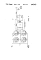
- FIG. 3 is a schematic diagram of one embodiment of the gate drive circuits for two of the switching devices illustrated in FIG. 1.
- FIG. 4a illustrates the transformer drive voltage of the circuit of FIG. 1.
- FIG. 4b illustrates the gate drive voltage as a function of time for one of the switching devices in FIG. 1.
- FIG. 4c illustrates the gate drive voltage as a function of time for a second of the switching devices illustrated in FIG. 4b.
- FIG. 1 illustrates a lossless switching full-bridge converter 2 in which the input is driven by dc source voltage E d .
- converters of the type shown in FIG. 1 have been referred to as “edge resonant” or “transition resonant” converters.
- Input capacitor C i smooths input voltage E d and stores energy returned to the source from the components of the full bridge.
- high voltage switching devices S1, S2, S3 and S4 FET transistors
- the series combination of switching devices 51 and S2 is connected in parallel across capacitors C i and the series combination of switching devices S3 and S4.
- parasitic capacitance PC1 and parasitic diode PD1 are connected across the drain and source leads of ideal FET switch Q1.
- Q1 is an ideal FET while PD1 is its inverse parallel parasitic diode and PC1 is its parasitic output capacitance (the sum of the drain-gate and drain-source capacitances).
- Parasitic capacitors PC2-PC4 and parasitic diodes PD2-PD4 are likewise connected across the source and drain electrodes of ideal FET switches Q2-Q4. These parasitic capacitors and diodes represent actual parasitic devices which result from the geometry of the switching device.
- the node connection between S1 and S2 is labeled a.
- the other end of the T transformer primary is labeled b and is located at the node between switching devices S3 and S4.
- Transformer T consists of ideal transformer T1, leakage inductance L 1 and magnetizing inductance L M .
- the output of transformer T is connected through a rectifying bridge consisting of diodes OD5 and OD6 to a low pass filter consisting of inductor L o and capacitor C o .
- the output voltage is labeled E o (typically 5 volts).
- the topology illustrated in FIG. 1 uses a minimum number of passive components. Only an input high-frequency bypass capacitor C i , an isolation transformer T, and an output filter L o , C o are necessary.
- the four switching devices S1-S4 in FIG. 1 have ratings (especially voltage ratings) considerably below the ratings required of transistors employed in other high-frequency switching converters. Therefore, the circuit of FIG. 1 is more amenable to integration which is desirable in order to achieve high power density.
- the topology of FIG. 1 results in very low switching losses.
- the output voltage may be controlled by phase-shifting of the two half-bridge legs (i.e., the voltage at nodes a and b) to control the output voltage E o .
- FIG. 2 illustrates the voltage waveform applied to high-frequency transformer T (i.e., the voltage between points a and b) during normal operation.
- T high-frequency transformer
- FIG. 2 illustrates the conducting devices during each interval of operation over a complete cycle. For example, Q1 and Q4 both conduct during interval 1. Interval 1 ends when Q1 stops conducting. During interval 2, capacitors PC1, PC2 and switching device Q4 conduct. The actual operaton of the circuit of FIG. 1 may now be described in greater detail with reference to the waveform of FIG. 2.
- interval 3 the voltage between points a and b is zero as current, which is maintained by L M and L 1 , circulates through Q4 and PD2.
- the voltage at point c on the secondary side of the transformer is also near zero, however, output inductor L o , maintains current at the output such that the voltage across the output load remains substantially constant. Interval 3 continues until Q4 turns off.
- interval 2 plus interval 3 time, alpha is controllable and may be used to regulate the output voltage. Control of this interval is accomplished by means of switching device Q4 which may be turned off at anytime during interval 2 or 3. When Q4 is turned off, PC3, PC4 and PD2 conduct. The RMS voltage of the transformer drive is increased as the duration of intervals 4 to 7 increases in FIG. 2.
- the current in the leakage inductance reverses rapidly as PD3 begins to conduct since the full dc voltage is applied to the leakage inductance L 1 .
- the current in the larger magnetizing inductance L M also begins to reverse (the current in the magnetizing inductance is approximately a triangular wave over a complete cycle).
- L M and L 1 are magnetizing inductance L M and L 1 depending on the application. Some magnetizing inductance L M is necessary to provide current to charge and discharge capacitors PC1-PC4 during no load (i.e., where the current in L 1 is zero due to a no load condition at the converter output). However, there is an incentive to keep the peak current in L M as low as possible, since the current rating of the FETS used for switching devices Q1-Q4 must be sufficient to carry the full load primary current and the current in L M . In addition, increasing L M increases the time required to reverse the transformer current (e.g., during interval 5 of FIG. 2) which lowers the operating frequency of the converter. At full load, the current in L M may be very small since leakage inductance L 1 can provide inductive energy for charging and discharging the device capacitances.
- L 1 could be minimized, and L M could be designed to provide the inductive energy needed to achieve the charging and discharging of the device capacitances during both full and no load conditions.
- the peak current in L M would have to be greater than the full load current (reflected to the primary side) in order to overcome the tendency of the current in L M to circulate through the primary of ideal transformer T1 when the transformer secondary is effectively shorted (e.g., during interval 3).
- a finite L M may be obtained by using a Nickel-Zinc Ferrite material for the transformer core.
- Nickel-Zinc has a relatively low permeability which results in a non-negligible magnetizing inductance, L M .
- "Nickel-Zinc” is suited to operation above 1 MHz where the conventional power Ferrites (Manganese-Zinc) have excessive core losses.
- "Nickel-Zinc” thus provides a high frequency transformer core with a predictable, non-negligible magnetizing inductance. This material may, therefore, be used advantageously to construct transformer T.
- Leakage inductance L 1 is inevitable in transformer design. However, leakage inductance is primarily a function of the transformer structure and the coupling between the transformer primary and secondary. Therefore, it is to a great extent controllable. By properly designing transformer T of FIG. 1, it is possible to obtain a leakage inductance which will work with the magnetizing inductance. In summary, transformer T of FIG. 1 is practical and realizable.
- control of the converter is by relative phase shift of the two converter half-bridge legs, instantaneous switching of the converter legs in response to a sensed parameter is not required. That is, since the output voltage is a function of the relative phase shift between the two inverter legs, the absolute values of delays in logic circuitry from a master oscillator to the gate drivers is not critical: It is the relative timing of the gate drive signals which is of importance, since it is the relative timing which determines the phase relationship between the currents in the half-bridge legs. Phase shifting the converter half-bridge legs relative to one another even provides a means of reducing the output voltage to zero. Further, since it is possible to shift the phases almost instantaneously, this capability provides protection from output shorts.
- Absolute zero output voltage is attained by switching such that the voltage on the two converter legs are exactly in phase (i.e., the voltage at points a and b in FIG. 1 would rise and fall together) thus providing an effective current limit.
- the rate of output current rise when a short is encountered is limited by the output filter inductor, L o .
- diodes PD2 and PD3 are both conducting.
- FET Q2 can be gated on during interval 3 or 4.
- switching device Q3, which is in inverse parallel with diodes PD3, is gated on so that, as the load current reverses, switching devices Q2 (which was gated during interval 4) and Q3 are ready to carry the current.
- Q3 cannot be gated on too early (for example during interval 4) because this would result in the FET output capacitances being discharged through the switching devices with a resulting loss of energy.
- switching device Q3 must be gated on at precisely the right moment during the interval 5. Note that the time when interval 5 begins is not predictable since the length of interval 4 is a function of the current.
- FIG. 3 illustrates one embodiment of two of the four gate drivers necessary to drive switching devices Q1-Q2 of FIG. 1.
- Upper gate driver 10 and lower gate driver 12 drive switching devices Q1 and Q2 respectively.
- Substantially identical gate drivers could be used to drive switching devices Q3 and Q4. All of the transistors illustrated in FIG. 3 are enhancement mode, insulated gate field effect transistors.
- upper gate driver 10 is adapted to control transistor Q1 during both start-up and steady state operation.
- the currents in inductors L 1 and L M have not yet been established. Therefore, the voltage at node a remains constant until either Q1 or Q2 are activated. Therefore, voltage VP2 is provided to initiate interval 1.
- VP2 is normally off; when it turns on, Q10 turns on which activates Q33 and turns Q1 on through Q7.
- Q10 also activates Q21 which raises the voltage at the gate of Q32, which removes the turn-off gate drive of Q1.
- Q1 may be turned off by means of a voltage VP1.
- Q9 turns on which turns on Q37 and Q32 through Q30 and Q5.
- gate driver 12 acts in a substantially identical manner to control the operation of Q2.
- gate drivers 10 and 12 include voltage sensors 14 and 16 which are designed to turn transistors Q1 and Q2 on at precisely the instant necessary to ensure substantially lossless switching.
- Gate drive circuits 10 and 12 sense when the voltage across the respective switching devices Q1 and Q2 approach zero and gate the switching device on when this happens so that it is ready to carry the primary current as it reverses.
- switching device Q1 is a p-channel power device
- switching device Q2 is an n-channel power device. This configuration is used in the embodiment of FIG. 3 because it facilitates integration of the gate drivers and switching devices on a single chip, while minimizing the capacitive substrate currents which result from the high rates of change of voltage at point a.
- the keys to improved gate drivers 10 and 12 are voltage sensors 14 and 16, respectively, which are shown inside the heavy dotted lines in FIG. 3.
- Voltage sensor 14 senses the voltage across switching device Q1.
- Voltage sensor 16 senses the voltage across switching device Q2.
- the voltage of node a is a function of the magnetizing and leakage inductance currents as explained previously.
- the sense FET Q8 turns on through diode D2, which turns on Q1 through Q33 and Q7.
- Q1 is ready to conduct when the load current reverses.
- a signal to command the FETs to turn on is given by the control logic at a time known to be later than needed for proper circuit operation (that is, the FET voltage sensing devices will normally turn the power FETs on).
- These control turn-on commands are intended to get the circuit started because load current will not be available at start-up to insure that the load voltage node, V LOAD , swings between the dc voltage rails.
- these logic circuits ensure proper operation of the circuit where the inductive currents are not sufficient to ensure proper operation of sense circuits 14 and 16.
- Diodes D2 and D1 protect the gate of Q8 from excessive reverse voltage when Q2 is conducting.
- FIG. 4 illustrates the waveforms associated with the gate drivers of FIG. 3, including voltage sense circuits 14 and 16.
- FIG. 4(a) illustrates the output voltage between points a and b of FIG. 1.
- FIG. 4(b) illustrates the drive voltage at the gate of transistor Q1.
- FIG. 4(c) illustrates the drive voltage at the gate of transistor Q4.
- Q1 Since Q1 is a P-channel metal oxide semiconductor PMOS transistor (see FIG. 3), it turns on as its gate drive voltage approaches E i and turns off as its gate drive voltage approaches E d .
- E i is an intermediate voltage which is normally 15 volts below E d in the embodiment of FIG. 3. Therefore, at the end of interval 1, as the gate drive to Q1 is increased from approximately E i to E d , Q1 turns off. Q1 turns on again as the voltage at node a approaches E d at the end of interval 9. This period is indicated in dashed lines in FIG.
- FIG. 4(c) the drive voltage to the gate of Q4 is illustrated.
- the gate driver circuit for Q4 would be substantially identical to gate driver 12 of FIG. 3, including voltage sensor 16.
- a voltage sensor similar to voltage sensor 16, turns on Q4. Since the voltage at point b reaches the required potential some time during interval 9, Q4 turns on during that interval.
- a substantially identical analysis will apply to the operation of switching devices Q3 and Q2.
- the Full-Bridge Lossless Switching Converter of the present invention has several advantages for high frequency, high density power conversion.
- the energy stored in FET output capacitances is not dissipated, but rather is returned to the dc source resulting in low switching losses.
- the switching devices may be FETs having relatively low voltage and current ratings making them more amenable to integration.
- the converter of the present invention operates in the 1 to 10 MHz range at efficiencies of approximately 85% or more. Voltage control is achieved by simply phase shifting the converter half-bridge legs relative to one another, thus enabling the converter to operate at a single frequency from full to no load. Finally, a minimum number of passive components is used, enhancing the degree of size reduction attainable through integration of the converter.
Abstract
Description
Claims (8)
Priority Applications (1)
| Application Number | Priority Date | Filing Date | Title |
|---|---|---|---|
| US07/164,600 US4912622A (en) | 1988-03-07 | 1988-03-07 | Gate driver for a full-bridge lossless switching device |
Applications Claiming Priority (1)
| Application Number | Priority Date | Filing Date | Title |
|---|---|---|---|
| US07/164,600 US4912622A (en) | 1988-03-07 | 1988-03-07 | Gate driver for a full-bridge lossless switching device |
Publications (1)
| Publication Number | Publication Date |
|---|---|
| US4912622A true US4912622A (en) | 1990-03-27 |
Family
ID=22595224
Family Applications (1)
| Application Number | Title | Priority Date | Filing Date |
|---|---|---|---|
| US07/164,600 Expired - Fee Related US4912622A (en) | 1988-03-07 | 1988-03-07 | Gate driver for a full-bridge lossless switching device |
Country Status (1)
| Country | Link |
|---|---|
| US (1) | US4912622A (en) |
Cited By (43)
| Publication number | Priority date | Publication date | Assignee | Title |
|---|---|---|---|---|
| US5173848A (en) * | 1991-09-06 | 1992-12-22 | Roof Richard W | Motor controller with bi-modal turnoff circuits |
| US5180964A (en) * | 1990-03-28 | 1993-01-19 | Ewing Gerald D | Zero-voltage switched FM-PWM converter |
| US5285372A (en) * | 1991-10-23 | 1994-02-08 | Henkel Corporation | Power supply for an ozone generator with a bridge inverter |
| US5291384A (en) * | 1991-06-20 | 1994-03-01 | Unitrode Corporation | Phase shifted switching controller |
| US5406051A (en) * | 1993-04-29 | 1995-04-11 | Electric Power Research Institute | Welding machine with a high frequency converter |
| US5514921A (en) * | 1994-06-27 | 1996-05-07 | General Electric Company | Lossless gate drivers for high-frequency PWM switching cells |
| US5594629A (en) * | 1994-06-20 | 1997-01-14 | General Electric Company | High-frequency switching circuits operable in a natural zero-voltage switching mode |
| US6259615B1 (en) | 1999-07-22 | 2001-07-10 | O2 Micro International Limited | High-efficiency adaptive DC/AC converter |
| US6301135B1 (en) | 1999-03-01 | 2001-10-09 | Texas Instruments Incorporated | Isolated switching-mode power supply control circuit having secondary-side controller and supervisory primary-side controller |
| US20020149637A1 (en) * | 2001-03-26 | 2002-10-17 | Canon Kabushiki Kaisha | Method of driving and controlling ink jet print head, ink jet print head, and ink jet printer |
| US20020180403A1 (en) * | 2001-05-24 | 2002-12-05 | Brown Fred A. | Efficient stator |
| US6501234B2 (en) | 2001-01-09 | 2002-12-31 | 02 Micro International Limited | Sequential burst mode activation circuit |
| US6504739B2 (en) | 2001-05-18 | 2003-01-07 | Astec International Limited | Simple control circuit for synchronous rectifiers used in ZVS phase shifted full bridge converter |
| US6531831B2 (en) | 2000-05-12 | 2003-03-11 | O2Micro International Limited | Integrated circuit for lamp heating and dimming control |
| US6570344B2 (en) | 2001-05-07 | 2003-05-27 | O2Micro International Limited | Lamp grounding and leakage current detection system |
| US20030227452A1 (en) * | 2002-06-07 | 2003-12-11 | Alexandru Hartular | Adaptive LCD power supply circuit |
| US6756769B2 (en) | 2002-06-20 | 2004-06-29 | O2Micro International Limited | Enabling circuit for avoiding negative voltage transients |
| US20040178781A1 (en) * | 2003-01-22 | 2004-09-16 | Yung-Lin Lin | Controller and driving method for power circuits, electrical circuit for supplying energy and display device having the electrical circuit |
| US20040189095A1 (en) * | 2003-03-25 | 2004-09-30 | Yung-Lin Lin | Integrated power supply for an LCD panel |
| US6804129B2 (en) | 1999-07-22 | 2004-10-12 | 02 Micro International Limited | High-efficiency adaptive DC/AC converter |
| US20040207339A1 (en) * | 2003-04-15 | 2004-10-21 | Yung-Lin Lin | Power supply for an LCD panel |
| US6856519B2 (en) | 2002-05-06 | 2005-02-15 | O2Micro International Limited | Inverter controller |
| US6897698B1 (en) | 2003-05-30 | 2005-05-24 | O2Micro International Limited | Phase shifting and PWM driving circuits and methods |
| US20050168203A1 (en) * | 2004-01-29 | 2005-08-04 | Enpirion, Incorporated | Driver for a power converter and a method of driving a switch thereof |
| US20050174818A1 (en) * | 2004-02-11 | 2005-08-11 | Yung-Lin Lin | Liquid crystal display system with lamp feedback |
| US6949912B2 (en) | 2002-06-20 | 2005-09-27 | 02Micro International Limited | Enabling circuit for avoiding negative voltage transients |
| US20060077700A1 (en) * | 2002-04-24 | 2006-04-13 | O2 International Limited | High-efficiency adaptive DC/AC converter |
| US20070210777A1 (en) * | 2006-03-06 | 2007-09-13 | Cervera Pedro A | Controller for a power converter and method of operating the same |
| US20080018366A1 (en) * | 2006-07-20 | 2008-01-24 | Enpirion, Inc. | Driver for switch and a method of driving the same |
| US20080094114A1 (en) * | 2006-10-20 | 2008-04-24 | Mirmira Ramarao Dwarakanath | Controller including a sawtooth generator and method of operating the same |
| US20080265975A1 (en) * | 2007-04-25 | 2008-10-30 | Denso Corporation | Method for controlling vertical type MOSFET in bridge circuit |
| US20080310189A1 (en) * | 2007-06-05 | 2008-12-18 | Saab Ab | Intergrated power converter and gate driver circuit |
| US20090167267A1 (en) * | 2007-12-27 | 2009-07-02 | Mirmira Ramarao Dwarakanath | Power Converter with Monotonic Turn-On for Pre-Charged Output Capacitor |
| US20090261791A1 (en) * | 2008-04-16 | 2009-10-22 | Lopata Douglas D | Power Converter with Power Switch Operable in Controlled Current Mode |
| US20100164449A1 (en) * | 2008-12-29 | 2010-07-01 | Mirmira Ramarao Dwarakanath | Power Converter with a Dynamically Configurable Controller and Output Filter |
| US20100164650A1 (en) * | 2008-12-29 | 2010-07-01 | Ahmed Mohamed Abou-Alfotouh | Power Converter with a Dynamically Configurable Controller and Output Filter |
| US20110095742A1 (en) * | 2008-04-16 | 2011-04-28 | Douglas Dean Lopata | Power Converter with Controller Operable in Selected Modes of Operation |
| US20110101934A1 (en) * | 2008-04-16 | 2011-05-05 | Douglas Dean Lopata | Power Converter with Controller Operable in Selected Modes of Operation |
| US20110101933A1 (en) * | 2008-04-16 | 2011-05-05 | Douglas Dean Lopata | Power Converter with Controller Operable in Selected Modes of Operation |
| US8686698B2 (en) | 2008-04-16 | 2014-04-01 | Enpirion, Inc. | Power converter with controller operable in selected modes of operation |
| US8867295B2 (en) | 2010-12-17 | 2014-10-21 | Enpirion, Inc. | Power converter for a memory module |
| US9246390B2 (en) | 2008-04-16 | 2016-01-26 | Enpirion, Inc. | Power converter with controller operable in selected modes of operation |
| US9509217B2 (en) | 2015-04-20 | 2016-11-29 | Altera Corporation | Asymmetric power flow controller for a power converter and method of operating the same |
Citations (20)
| Publication number | Priority date | Publication date | Assignee | Title |
|---|---|---|---|---|
| US3976932A (en) * | 1975-04-15 | 1976-08-24 | General Electric Company | Bridge transistor inverter circuit |
| US4027228A (en) * | 1975-04-15 | 1977-05-31 | General Electric Company | Photocoupled isolated switching amplifier circuit |
| US4413313A (en) * | 1980-10-07 | 1983-11-01 | Texas Instruments Incorporated | Electrical inverters |
| US4502085A (en) * | 1982-10-26 | 1985-02-26 | Westinghouse Electric Corp. | Power amplifier with controllable lossless snubber circuit |
| US4504895A (en) * | 1982-11-03 | 1985-03-12 | General Electric Company | Regulated dc-dc converter using a resonating transformer |
| US4533986A (en) * | 1983-10-31 | 1985-08-06 | General Electric Company | Compact electrical power supply for signal processing applications |
| US4541041A (en) * | 1983-08-22 | 1985-09-10 | General Electric Company | Full load to no-load control for a voltage fed resonant inverter |
| US4546422A (en) * | 1982-12-28 | 1985-10-08 | Tokyo Shibaura Denki Kabushiki Kaisha | Control system for a voltage-type inverter |
| US4566059A (en) * | 1983-07-21 | 1986-01-21 | Venus Scientific Inc. | Converter with lossless snubbing components |
| US4628426A (en) * | 1985-10-31 | 1986-12-09 | General Electric Company | Dual output DC-DC converter with independently controllable output voltages |
| US4639849A (en) * | 1985-05-08 | 1987-01-27 | International Exide Electronics/Corporation | Snubber circuit for H.F. bridge converter |
| US4672528A (en) * | 1986-05-27 | 1987-06-09 | General Electric Company | Resonant inverter with improved control |
| US4691270A (en) * | 1986-07-22 | 1987-09-01 | Rca Corporation | Current fed inverter bridge with lossless snubbers |
| US4694384A (en) * | 1986-12-04 | 1987-09-15 | General Electric Company | HVIC power supply controller with primary-side edge detector |
| US4700285A (en) * | 1986-11-18 | 1987-10-13 | National Semiconductor Corporation | Combined PWM-FM control method and circuit for the high efficiency control of resonant switch mode inverters/converters |
| US4709316A (en) * | 1985-12-27 | 1987-11-24 | General Electric Company | Single-ended DC-to-DC converter with lossless switching |
| US4727272A (en) * | 1984-05-16 | 1988-02-23 | A.N.V.A.R. | Drive-interface for a static electronic switch with controlled "off" |
| US4730242A (en) * | 1986-09-25 | 1988-03-08 | Wisconsin Alumni Research Foundation | Static power conversion and apparatus having essentially zero switching losses |
| US4757432A (en) * | 1981-11-17 | 1988-07-12 | Hughes Aircraft Company | Series resonant inverter with integrating feedback control loop |
| US4788634A (en) * | 1987-06-22 | 1988-11-29 | Massachusetts Institute Of Technology | Resonant forward converter |
-
1988
- 1988-03-07 US US07/164,600 patent/US4912622A/en not_active Expired - Fee Related
Patent Citations (20)
| Publication number | Priority date | Publication date | Assignee | Title |
|---|---|---|---|---|
| US4027228A (en) * | 1975-04-15 | 1977-05-31 | General Electric Company | Photocoupled isolated switching amplifier circuit |
| US3976932A (en) * | 1975-04-15 | 1976-08-24 | General Electric Company | Bridge transistor inverter circuit |
| US4413313A (en) * | 1980-10-07 | 1983-11-01 | Texas Instruments Incorporated | Electrical inverters |
| US4757432A (en) * | 1981-11-17 | 1988-07-12 | Hughes Aircraft Company | Series resonant inverter with integrating feedback control loop |
| US4502085A (en) * | 1982-10-26 | 1985-02-26 | Westinghouse Electric Corp. | Power amplifier with controllable lossless snubber circuit |
| US4504895A (en) * | 1982-11-03 | 1985-03-12 | General Electric Company | Regulated dc-dc converter using a resonating transformer |
| US4546422A (en) * | 1982-12-28 | 1985-10-08 | Tokyo Shibaura Denki Kabushiki Kaisha | Control system for a voltage-type inverter |
| US4566059A (en) * | 1983-07-21 | 1986-01-21 | Venus Scientific Inc. | Converter with lossless snubbing components |
| US4541041A (en) * | 1983-08-22 | 1985-09-10 | General Electric Company | Full load to no-load control for a voltage fed resonant inverter |
| US4533986A (en) * | 1983-10-31 | 1985-08-06 | General Electric Company | Compact electrical power supply for signal processing applications |
| US4727272A (en) * | 1984-05-16 | 1988-02-23 | A.N.V.A.R. | Drive-interface for a static electronic switch with controlled "off" |
| US4639849A (en) * | 1985-05-08 | 1987-01-27 | International Exide Electronics/Corporation | Snubber circuit for H.F. bridge converter |
| US4628426A (en) * | 1985-10-31 | 1986-12-09 | General Electric Company | Dual output DC-DC converter with independently controllable output voltages |
| US4709316A (en) * | 1985-12-27 | 1987-11-24 | General Electric Company | Single-ended DC-to-DC converter with lossless switching |
| US4672528A (en) * | 1986-05-27 | 1987-06-09 | General Electric Company | Resonant inverter with improved control |
| US4691270A (en) * | 1986-07-22 | 1987-09-01 | Rca Corporation | Current fed inverter bridge with lossless snubbers |
| US4730242A (en) * | 1986-09-25 | 1988-03-08 | Wisconsin Alumni Research Foundation | Static power conversion and apparatus having essentially zero switching losses |
| US4700285A (en) * | 1986-11-18 | 1987-10-13 | National Semiconductor Corporation | Combined PWM-FM control method and circuit for the high efficiency control of resonant switch mode inverters/converters |
| US4694384A (en) * | 1986-12-04 | 1987-09-15 | General Electric Company | HVIC power supply controller with primary-side edge detector |
| US4788634A (en) * | 1987-06-22 | 1988-11-29 | Massachusetts Institute Of Technology | Resonant forward converter |
Non-Patent Citations (4)
| Title |
|---|
| Liu et al., "Zero Voltage Switching Technique In DC/DC Converters"; pp. 58-70. |
| Liu et al., Zero Voltage Switching Technique In DC/DC Converters ; pp. 58 70. * |
| R. L. Steigerwald, "High Frequency Resonant Transistor DC-DC Converters," IEEE Trans. Ind. Electron, IE-31, pp. 181-191, May 1984. |
| R. L. Steigerwald, High Frequency Resonant Transistor DC DC Converters, IEEE Trans. Ind. Electron, IE 31, pp. 181 191, May 1984. * |
Cited By (93)
| Publication number | Priority date | Publication date | Assignee | Title |
|---|---|---|---|---|
| US5180964A (en) * | 1990-03-28 | 1993-01-19 | Ewing Gerald D | Zero-voltage switched FM-PWM converter |
| US5291384A (en) * | 1991-06-20 | 1994-03-01 | Unitrode Corporation | Phase shifted switching controller |
| US5173848A (en) * | 1991-09-06 | 1992-12-22 | Roof Richard W | Motor controller with bi-modal turnoff circuits |
| US5285372A (en) * | 1991-10-23 | 1994-02-08 | Henkel Corporation | Power supply for an ozone generator with a bridge inverter |
| US5406051A (en) * | 1993-04-29 | 1995-04-11 | Electric Power Research Institute | Welding machine with a high frequency converter |
| US5594629A (en) * | 1994-06-20 | 1997-01-14 | General Electric Company | High-frequency switching circuits operable in a natural zero-voltage switching mode |
| US5514921A (en) * | 1994-06-27 | 1996-05-07 | General Electric Company | Lossless gate drivers for high-frequency PWM switching cells |
| US6301135B1 (en) | 1999-03-01 | 2001-10-09 | Texas Instruments Incorporated | Isolated switching-mode power supply control circuit having secondary-side controller and supervisory primary-side controller |
| US6259615B1 (en) | 1999-07-22 | 2001-07-10 | O2 Micro International Limited | High-efficiency adaptive DC/AC converter |
| US6396722B2 (en) | 1999-07-22 | 2002-05-28 | Micro International Limited | High-efficiency adaptive DC/AC converter |
| US7417382B2 (en) | 1999-07-22 | 2008-08-26 | O2Micro International Limited | High-efficiency adaptive DC/AC converter |
| US20020180380A1 (en) * | 1999-07-22 | 2002-12-05 | Yung-Lin Lin | High-efficiency adaptive DC/AC converter |
| US20080246413A1 (en) * | 1999-07-22 | 2008-10-09 | O2Micro, Inc. | Dc/ac cold cathode fluorescent lamp inverter |
| US7515445B2 (en) | 1999-07-22 | 2009-04-07 | 02Micro International Limited | High-efficiency adaptive DC/AC converter |
| US20050030776A1 (en) * | 1999-07-22 | 2005-02-10 | Yung-Lin Lin | High-efficiency adaptive DC/AC converter |
| US7881084B2 (en) | 1999-07-22 | 2011-02-01 | O2Micro International Limited | DC/AC cold cathode fluorescent lamp inverter |
| US6804129B2 (en) | 1999-07-22 | 2004-10-12 | 02 Micro International Limited | High-efficiency adaptive DC/AC converter |
| US6531831B2 (en) | 2000-05-12 | 2003-03-11 | O2Micro International Limited | Integrated circuit for lamp heating and dimming control |
| US6707264B2 (en) | 2001-01-09 | 2004-03-16 | 2Micro International Limited | Sequential burst mode activation circuit |
| US7847491B2 (en) | 2001-01-09 | 2010-12-07 | O2Micro International Limited | Sequential burst mode activation circuit |
| US20040183469A1 (en) * | 2001-01-09 | 2004-09-23 | Yung-Lin Lin | Sequential burnst mode activation circuit |
| US7477024B2 (en) | 2001-01-09 | 2009-01-13 | O2Micro International Limited | Sequential burst mode activation circuit |
| US6501234B2 (en) | 2001-01-09 | 2002-12-31 | 02 Micro International Limited | Sequential burst mode activation circuit |
| US20090218954A1 (en) * | 2001-01-09 | 2009-09-03 | O2Micro International | Sequential burst mode actlvation circuit |
| US20020149637A1 (en) * | 2001-03-26 | 2002-10-17 | Canon Kabushiki Kaisha | Method of driving and controlling ink jet print head, ink jet print head, and ink jet printer |
| US6570344B2 (en) | 2001-05-07 | 2003-05-27 | O2Micro International Limited | Lamp grounding and leakage current detection system |
| US6504739B2 (en) | 2001-05-18 | 2003-01-07 | Astec International Limited | Simple control circuit for synchronous rectifiers used in ZVS phase shifted full bridge converter |
| US20020180403A1 (en) * | 2001-05-24 | 2002-12-05 | Brown Fred A. | Efficient stator |
| US7515446B2 (en) | 2002-04-24 | 2009-04-07 | O2Micro International Limited | High-efficiency adaptive DC/AC converter |
| US20060077700A1 (en) * | 2002-04-24 | 2006-04-13 | O2 International Limited | High-efficiency adaptive DC/AC converter |
| US6856519B2 (en) | 2002-05-06 | 2005-02-15 | O2Micro International Limited | Inverter controller |
| US20030227452A1 (en) * | 2002-06-07 | 2003-12-11 | Alexandru Hartular | Adaptive LCD power supply circuit |
| US6873322B2 (en) | 2002-06-07 | 2005-03-29 | 02Micro International Limited | Adaptive LCD power supply circuit |
| US6906497B2 (en) | 2002-06-20 | 2005-06-14 | O2Micro International Limited | Enabling circuit for avoiding negative voltage transients |
| US7112943B2 (en) | 2002-06-20 | 2006-09-26 | O2Micro International Limited | Enabling circuit for avoiding negative voltage transients |
| US6949912B2 (en) | 2002-06-20 | 2005-09-27 | 02Micro International Limited | Enabling circuit for avoiding negative voltage transients |
| US6756769B2 (en) | 2002-06-20 | 2004-06-29 | O2Micro International Limited | Enabling circuit for avoiding negative voltage transients |
| US20040178781A1 (en) * | 2003-01-22 | 2004-09-16 | Yung-Lin Lin | Controller and driving method for power circuits, electrical circuit for supplying energy and display device having the electrical circuit |
| US7200017B2 (en) | 2003-01-22 | 2007-04-03 | O2Micro International Limited | Controller and driving method for supplying energy to display device circuitry |
| US20040189095A1 (en) * | 2003-03-25 | 2004-09-30 | Yung-Lin Lin | Integrated power supply for an LCD panel |
| US7057611B2 (en) | 2003-03-25 | 2006-06-06 | 02Micro International Limited | Integrated power supply for an LCD panel |
| US6936975B2 (en) | 2003-04-15 | 2005-08-30 | 02Micro International Limited | Power supply for an LCD panel |
| US20040207339A1 (en) * | 2003-04-15 | 2004-10-21 | Yung-Lin Lin | Power supply for an LCD panel |
| US20040263092A1 (en) * | 2003-04-15 | 2004-12-30 | Da Liu | Driving circuit for multiple cold cathode fluorescent lamps |
| US8179053B2 (en) | 2003-04-15 | 2012-05-15 | O2Micro International Limited | Power supply for an LCD display |
| US20060202635A1 (en) * | 2003-04-15 | 2006-09-14 | O2Micro Inc | Driving circuit for multiple cold cathode fluorescent lamps backlight applications |
| US7075245B2 (en) | 2003-04-15 | 2006-07-11 | 02 Micro, Inc | Driving circuit for multiple cold cathode fluorescent lamps backlight applications |
| US7550928B2 (en) | 2003-04-15 | 2009-06-23 | O2Micro International Limited | Driving circuit for multiple cold cathode fluorescent lamps backlight applications |
| US20090039796A1 (en) * | 2003-04-15 | 2009-02-12 | Yung-Lin Lin | Power supply for an lcd display |
| US6897698B1 (en) | 2003-05-30 | 2005-05-24 | O2Micro International Limited | Phase shifting and PWM driving circuits and methods |
| US7710093B2 (en) | 2004-01-29 | 2010-05-04 | Enpirion, Inc. | Driver for a power converter and a method of driving a switch thereof |
| US20050168203A1 (en) * | 2004-01-29 | 2005-08-04 | Enpirion, Incorporated | Driver for a power converter and a method of driving a switch thereof |
| US7330017B2 (en) * | 2004-01-29 | 2008-02-12 | Enpirion, Inc. | Driver for a power converter and a method of driving a switch thereof |
| US20050174818A1 (en) * | 2004-02-11 | 2005-08-11 | Yung-Lin Lin | Liquid crystal display system with lamp feedback |
| US7394209B2 (en) | 2004-02-11 | 2008-07-01 | 02 Micro International Limited | Liquid crystal display system with lamp feedback |
| US7521907B2 (en) | 2006-03-06 | 2009-04-21 | Enpirion, Inc. | Controller for a power converter and method of operating the same |
| US20070210777A1 (en) * | 2006-03-06 | 2007-09-13 | Cervera Pedro A | Controller for a power converter and method of operating the same |
| US20090212751A1 (en) * | 2006-03-06 | 2009-08-27 | Pedro Alou Cervera | Controller for a Power Converter and Method of Operating The Same |
| US9748840B2 (en) | 2006-03-06 | 2017-08-29 | Altera Corporation | Controller for a power converter and method of operating the same |
| US8736241B2 (en) | 2006-03-06 | 2014-05-27 | Enpirion, Inc. | Controller for a power converter and method of operating the same |
| US8013580B2 (en) | 2006-03-06 | 2011-09-06 | Enpirion, Inc. | Controller for a power converter and method of operating the same |
| US20080018366A1 (en) * | 2006-07-20 | 2008-01-24 | Enpirion, Inc. | Driver for switch and a method of driving the same |
| US7893676B2 (en) | 2006-07-20 | 2011-02-22 | Enpirion, Inc. | Driver for switch and a method of driving the same |
| US20080094114A1 (en) * | 2006-10-20 | 2008-04-24 | Mirmira Ramarao Dwarakanath | Controller including a sawtooth generator and method of operating the same |
| US7948280B2 (en) | 2006-10-20 | 2011-05-24 | Enpirion, Inc. | Controller including a sawtooth generator and method of operating the same |
| US7714624B2 (en) * | 2007-04-25 | 2010-05-11 | Denso Corporation | Method for controlling vertical type MOSFET in bridge circuit |
| US20080265975A1 (en) * | 2007-04-25 | 2008-10-30 | Denso Corporation | Method for controlling vertical type MOSFET in bridge circuit |
| US7952340B2 (en) * | 2007-06-05 | 2011-05-31 | Saab Ab | Integrated power converter and gate driver circuit |
| US20080310189A1 (en) * | 2007-06-05 | 2008-12-18 | Saab Ab | Intergrated power converter and gate driver circuit |
| US7876080B2 (en) | 2007-12-27 | 2011-01-25 | Enpirion, Inc. | Power converter with monotonic turn-on for pre-charged output capacitor |
| US20090167267A1 (en) * | 2007-12-27 | 2009-07-02 | Mirmira Ramarao Dwarakanath | Power Converter with Monotonic Turn-On for Pre-Charged Output Capacitor |
| US8283901B2 (en) | 2008-04-16 | 2012-10-09 | Enpirion, Inc. | Power converter with power switch operable in controlled current mode |
| US8686698B2 (en) | 2008-04-16 | 2014-04-01 | Enpirion, Inc. | Power converter with controller operable in selected modes of operation |
| US20110101933A1 (en) * | 2008-04-16 | 2011-05-05 | Douglas Dean Lopata | Power Converter with Controller Operable in Selected Modes of Operation |
| US20110095742A1 (en) * | 2008-04-16 | 2011-04-28 | Douglas Dean Lopata | Power Converter with Controller Operable in Selected Modes of Operation |
| US20090261791A1 (en) * | 2008-04-16 | 2009-10-22 | Lopata Douglas D | Power Converter with Power Switch Operable in Controlled Current Mode |
| US9246390B2 (en) | 2008-04-16 | 2016-01-26 | Enpirion, Inc. | Power converter with controller operable in selected modes of operation |
| US8154261B2 (en) | 2008-04-16 | 2012-04-10 | Enpirion, Inc. | Power converter with power switch operable in controlled current mode |
| US20100156374A1 (en) * | 2008-04-16 | 2010-06-24 | Lopata Douglas D | Power Converter with Power Switch Operable in Controlled Current Mode |
| US20100141228A1 (en) * | 2008-04-16 | 2010-06-10 | Lopata Douglas D | Power Converter with Power Switch Operable in Controlled Current Mode |
| US8410769B2 (en) | 2008-04-16 | 2013-04-02 | Enpirion, Inc. | Power converter with controller operable in selected modes of operation |
| US8541991B2 (en) | 2008-04-16 | 2013-09-24 | Enpirion, Inc. | Power converter with controller operable in selected modes of operation |
| US20110101934A1 (en) * | 2008-04-16 | 2011-05-05 | Douglas Dean Lopata | Power Converter with Controller Operable in Selected Modes of Operation |
| US8692532B2 (en) | 2008-04-16 | 2014-04-08 | Enpirion, Inc. | Power converter with controller operable in selected modes of operation |
| US7679342B2 (en) | 2008-04-16 | 2010-03-16 | Enpirion, Inc. | Power converter with power switch operable in controlled current mode |
| US8698463B2 (en) | 2008-12-29 | 2014-04-15 | Enpirion, Inc. | Power converter with a dynamically configurable controller based on a power conversion mode |
| US20100164449A1 (en) * | 2008-12-29 | 2010-07-01 | Mirmira Ramarao Dwarakanath | Power Converter with a Dynamically Configurable Controller and Output Filter |
| US9548714B2 (en) | 2008-12-29 | 2017-01-17 | Altera Corporation | Power converter with a dynamically configurable controller and output filter |
| US20100164650A1 (en) * | 2008-12-29 | 2010-07-01 | Ahmed Mohamed Abou-Alfotouh | Power Converter with a Dynamically Configurable Controller and Output Filter |
| US8867295B2 (en) | 2010-12-17 | 2014-10-21 | Enpirion, Inc. | Power converter for a memory module |
| US9627028B2 (en) | 2010-12-17 | 2017-04-18 | Enpirion, Inc. | Power converter for a memory module |
| US9509217B2 (en) | 2015-04-20 | 2016-11-29 | Altera Corporation | Asymmetric power flow controller for a power converter and method of operating the same |
| US10084380B2 (en) | 2015-04-20 | 2018-09-25 | Altera Corporation | Asymmetric power flow controller for a power converter and method of operating the same |
Similar Documents
| Publication | Publication Date | Title |
|---|---|---|
| US4912622A (en) | Gate driver for a full-bridge lossless switching device | |
| US4864479A (en) | Full-bridge lossless switching converter | |
| US5781419A (en) | Soft switching DC-to-DC converter with coupled inductors | |
| US5438498A (en) | Series resonant converter having a resonant snubber | |
| US4857822A (en) | Zero-voltage-switched multi-resonant converters including the buck and forward type | |
| US8278972B2 (en) | Method and apparatus for simplifying the control of a switch | |
| EP0712546B1 (en) | Pulse width modulated dc-to-dc boost converter | |
| US5726869A (en) | Synchronous rectifier type DC-to-DC converter in which a saturable inductive device is connected in series with a secondary-side switching device | |
| CA1301245C (en) | Zero voltage switching half bridge resonant converter | |
| US5268830A (en) | Drive circuit for power switches of a zero-voltage switching power converter | |
| US5305191A (en) | Drive circuit for zero-voltage switching power converter with controlled power switch turn-on | |
| Oruganti et al. | Soft-switched DC/DC converter with PWM control | |
| US6434029B1 (en) | Boost topology having an auxiliary winding on the snubber inductor | |
| US5353212A (en) | Zero-voltage switching power converter with ripple current cancellation | |
| US5027263A (en) | Switching power source means | |
| US5694303A (en) | Semi-regulated power supply using forward converter leakage energy | |
| JP2004536543A (en) | Isolated drive circuit used in switch mode power converter | |
| US5822199A (en) | Controller for a power switch and method of operation thereof | |
| JPH01276819A (en) | Method of reducing electromagnetic interference in all bridge non-resonant switching circuit and all bridge non-resonant switching circuit | |
| JP2514872B2 (en) | DC power supply | |
| US5063488A (en) | Switching power source means | |
| US7570087B2 (en) | Switching drive circuit for soft switching | |
| US7362594B2 (en) | Adaptive resonant switching power system | |
| KR100199508B1 (en) | A zero-crossing voltage/current circuit for full-bridge dc/dc converter | |
| EP0942520A2 (en) | DC to DC power converter |
Legal Events
| Date | Code | Title | Description |
|---|---|---|---|
| AS | Assignment |
Owner name: GENERAL ELECTRIC COMPANY, A CORP. OF NEW YORK Free format text: ASSIGNMENT OF ASSIGNORS INTEREST.;ASSIGNORS:STEIGERWALD, ROBERT L.;NGO, KHAI D. T.;REEL/FRAME:004862/0206 Effective date: 19880307 Owner name: GENERAL ELECTRIC COMPANY, A CORP. OF NEW YORK, NE Free format text: ASSIGNMENT OF ASSIGNORS INTEREST;ASSIGNORS:STEIGERWALD, ROBERT L.;NGO, KHAI D. T.;REEL/FRAME:004862/0206 Effective date: 19880307 |
|
| FEPP | Fee payment procedure |
Free format text: PAYOR NUMBER ASSIGNED (ORIGINAL EVENT CODE: ASPN); ENTITY STATUS OF PATENT OWNER: LARGE ENTITY |
|
| FPAY | Fee payment |
Year of fee payment: 4 |
|
| AS | Assignment |
Owner name: NORWEST BANK OF MINNESOTA, NATIONAL ASSOCIATION, M Free format text: SECURITY AGREEMENT;ASSIGNOR:NORTHERN AMERICAN POWER SUPPLIES, INC.;REEL/FRAME:007894/0422 Effective date: 19960325 |
|
| AS | Assignment |
Owner name: NORWEST BANK MINNESOTA, NATIONAL ASSOCIATION, MINN Free format text: SECURITY AGREEMENT;ASSIGNOR:NORTH AMERICAN POWER SUPPLIES, INC.;REEL/FRAME:008146/0407 Effective date: 19960912 |
|
| FEPP | Fee payment procedure |
Free format text: PAYOR NUMBER ASSIGNED (ORIGINAL EVENT CODE: ASPN); ENTITY STATUS OF PATENT OWNER: LARGE ENTITY Free format text: PAYER NUMBER DE-ASSIGNED (ORIGINAL EVENT CODE: RMPN); ENTITY STATUS OF PATENT OWNER: LARGE ENTITY |
|
| FPAY | Fee payment |
Year of fee payment: 8 |
|
| SULP | Surcharge for late payment | ||
| REMI | Maintenance fee reminder mailed | ||
| LAPS | Lapse for failure to pay maintenance fees | ||
| STCH | Information on status: patent discontinuation |
Free format text: PATENT EXPIRED DUE TO NONPAYMENT OF MAINTENANCE FEES UNDER 37 CFR 1.362 |
|
| FP | Lapsed due to failure to pay maintenance fee |
Effective date: 20020327 |