US4913332A - Sheath release device for stapler - Google Patents
Sheath release device for stapler Download PDFInfo
- Publication number
- US4913332A US4913332A US07/300,511 US30051189A US4913332A US 4913332 A US4913332 A US 4913332A US 30051189 A US30051189 A US 30051189A US 4913332 A US4913332 A US 4913332A
- Authority
- US
- United States
- Prior art keywords
- sheath
- spring
- housing
- stapler
- crossbars
- Prior art date
- Legal status (The legal status is an assumption and is not a legal conclusion. Google has not performed a legal analysis and makes no representation as to the accuracy of the status listed.)
- Expired - Fee Related
Links
Images


Classifications
-
- B—PERFORMING OPERATIONS; TRANSPORTING
- B25—HAND TOOLS; PORTABLE POWER-DRIVEN TOOLS; MANIPULATORS
- B25C—HAND-HELD NAILING OR STAPLING TOOLS; MANUALLY OPERATED PORTABLE STAPLING TOOLS
- B25C1/00—Hand-held nailing tools; Nail feeding devices
- B25C1/08—Hand-held nailing tools; Nail feeding devices operated by combustion pressure
- B25C1/10—Hand-held nailing tools; Nail feeding devices operated by combustion pressure generated by detonation of a cartridge
- B25C1/14—Hand-held nailing tools; Nail feeding devices operated by combustion pressure generated by detonation of a cartridge acting on an intermediate plunger or anvil
-
- B—PERFORMING OPERATIONS; TRANSPORTING
- B25—HAND TOOLS; PORTABLE POWER-DRIVEN TOOLS; MANIPULATORS
- B25C—HAND-HELD NAILING OR STAPLING TOOLS; MANUALLY OPERATED PORTABLE STAPLING TOOLS
- B25C5/00—Manually operated portable stapling tools; Hand-held power-operated stapling tools; Staple feeding devices therefor
- B25C5/16—Staple-feeding devices, e.g. with feeding means, supports for staples or accessories concerning feeding devices
- B25C5/1665—Staple-feeding devices, e.g. with feeding means, supports for staples or accessories concerning feeding devices with means for preventing jamming or aiding unjamming within the drive channel
Definitions
- Staplers have been provided with sheaths positioned spaced-apart from the staple head base member with the space between the base member and the sheath providing a channel for movement of staple blanks as stripped from staple blank ribbons or sticks during transport, forming, driving, and clinching.
- Sheaths have been spaced apart using spacer lugs on the base member and a spring arrangement to urge the sheath against the spacer lugs (U.S. Pat. No. 4,570,841).
- the present invention comprises a sheath release means for unjamming a stapler comprising a mounting member capable of rotation in an opening in the sheath, a spring clamp member which during normal operation urges the sheath against the housing connected to the periphery of the rotatable mounting member crank means connected to the rotation member to partially rotate the member to move the spring member away from the housing.
- crank means may also function as the spring harness for holding the staple cartridge in position.
- FIG. 1 is a side elevational view of a stapler of the present invention with the spring retainer member engaging both the cartridge and the rotation element;
- FIG. 2 is an enlarged sectional view along line 2--2 of FIG. 1;
- FIG. 3 is a front partial elevational view of a stapler of the present invention in the process of driving a formed stapler;
- FIG. 4 is a side elevational view of the stapler with the cartridge spring retainer member freed from the cartridge and moved to the left to rotate the rotation member;
- FIG. 5 is an enlarged partial side view of the stapler including forming anvil, spring clamp and rotation member in their first tensioned position;
- FIG. 5a is a view similar to FIG. 5 with the assemblage released.
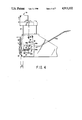
- FIG.6 is an enlarged partial elevational view of the sheath and spring clamp as released.
- stapler 10 includes a U-shaped housing 11, a generally U-shaped sheath 12 consisting of front sheath panel 12a, left panel 12b and right panel 12c (each at right angle to the front panel 12a), a cartridge 13 for delivering staple blanks to former block 14.
- Cartridge 13 is held in place by cartridge clamp spring 15 which snaps into cartridge groove 13a.
- Sheath and anvil spring 16 including spring loops 16a and 16b, spring side arms 16c and 16d, and rotation bars 30a, 30b urges forming block 14 against sheath 12 which in turn is urged against spacer lugs (not shown) on housing 11.
- staple S, driver 17, reciprocal former 19 which carries guide driver 17 as it reciprocates.
- Housing 11 includes sides 11a and 11b each of which carries a round aperture 21, 22 respectively.
- Each aperture 21, 22 has mounted in it for rotation therein a disk 21a, 22a preferably made of plastic.
- a pie-shaped segment 23a, 23b Positioned on the upper portion of each disk 21a, 21b is a pie-shaped segment 23a, 23b also preferably made of plastic.
- Each segment 21a, 23b has a hole 24a, 24b in it for receiving cartridge retainer spring horizontal projection portion 15a, 15b.
- sheath panel 12c preferably made of metal, carries sheath slot 11d in which spring arm 15a rides as it protrudes through hole 24a in segment 23a. Also shown is disk 21a and disk slot 21a and cartridge spring crank 15.
- housing side 11a has configured recess 40 shown partially in dashed lines.
- Recess 40 has lower recess portion 40a to accommodate spring crossbar 30a in its normal tensioned operating position and recess portion 40b to which bar 30 is rotated when spring clamp 15, serving as a crank, is used to rotated segment 23a and disk 21a which rotate as a unit.
- Housing side 11b has a similar configured recess (not shown).
- FIG. 2 shows pie-shaped segment 23a, segment hole 24a, spring arm 15a in hole 24a and further illustrates that spring crossbar 30a is moved upwardly to a position 30a' shown in solid and dashed lines when segment 23a and disk 21a are rotated. Also shown are aperture 21, right panel 12c and slot 11d in sheath panel 12c. Spring bar 30b (not shown) is similarly activated.
- cartridge 13 is held in position as cartridge spring 15 is snapped into groove 13a with spring arms 15a, 15b pulling segments 23a, 23b to the right as shown in FIG. 1, thus tending to rotate disks 21a, 21b clockwise.
- Spring clamp 16 is held firmly in operational position in recess portions 40a (FIG. 5).
- Disks 21a, 21b are positioned with their slots 20a, 20bin generally horizontal position (see FIGS. 1 and 5).
- cartridge spring 15 is snapped out of groove 13a releasing cartridge 13.
- Cartridge spring 15, now free, is urged to the left in FIGS. 1 and 4 to crank or rotate segments 23a (and 23b not shown), and attached disks 21a (and 21b not shown) causing spring 16 to move left as spring crossbars 30a, 30b move upwardly urged by slots 20a, 20b movement (FIGS. 4 and 5a).
- Spring arm 15a moves in recess 40 and arm 15b moves in its corresponding recess not shown.
- spring bars 30a, 30b snap into recess portions 40b, one in each housing side 11a, 11b.
- spring crossbars 30a, 30b which are integral parts of spring clamp 16
- sheath 12 swings about pivot pin 50 (see FIGS. 1 and 6) through an arc equal to angle A (FIG. 4).
- the pressure on forming block 14 is also reduced. As block 14 moves further left, jammed staples S can be removed.
Abstract
Description
Claims (4)
Priority Applications (12)
| Application Number | Priority Date | Filing Date | Title |
|---|---|---|---|
| US07/300,511 US4913332A (en) | 1989-01-23 | 1989-01-23 | Sheath release device for stapler |
| CA002006614A CA2006614A1 (en) | 1989-01-23 | 1989-12-22 | Sheath release device for stapler |
| MX019082A MX171942B (en) | 1989-01-23 | 1990-01-10 | LINER RELEASING DEVICE FOR STAPLERS |
| PT92847A PT92847A (en) | 1989-01-23 | 1990-01-11 | AGGRESSOR WITH SHELL RELEASE DEVICE |
| EP19900902897 EP0407563A4 (en) | 1989-01-23 | 1990-01-22 | Sheath release device for stapler |
| BR909004713A BR9004713A (en) | 1989-01-23 | 1990-01-22 | STAPLER |
| JP2503114A JP2660096B2 (en) | 1989-01-23 | 1990-01-22 | Document binding device sheath release device |
| PCT/US1990/000493 WO1990008014A1 (en) | 1989-01-23 | 1990-01-22 | Sheath release device for stapler |
| KR1019900701885A KR910700125A (en) | 1989-01-23 | 1990-01-22 | Stapler sheath release device |
| AU50403/90A AU633875B2 (en) | 1989-01-23 | 1990-01-22 | Sheath release device for stapler |
| NO903957A NO903957D0 (en) | 1989-01-23 | 1990-09-11 | COVER DISCHARGE DEVICE. |
| FI904676A FI904676A0 (en) | 1989-01-23 | 1990-09-21 | ANORDINATION FOR THE PURPOSE OF THE MEASURES. |
Applications Claiming Priority (1)
| Application Number | Priority Date | Filing Date | Title |
|---|---|---|---|
| US07/300,511 US4913332A (en) | 1989-01-23 | 1989-01-23 | Sheath release device for stapler |
Publications (1)
| Publication Number | Publication Date |
|---|---|
| US4913332A true US4913332A (en) | 1990-04-03 |
Family
ID=23159407
Family Applications (1)
| Application Number | Title | Priority Date | Filing Date |
|---|---|---|---|
| US07/300,511 Expired - Fee Related US4913332A (en) | 1989-01-23 | 1989-01-23 | Sheath release device for stapler |
Country Status (11)
| Country | Link |
|---|---|
| US (1) | US4913332A (en) |
| EP (1) | EP0407563A4 (en) |
| JP (1) | JP2660096B2 (en) |
| KR (1) | KR910700125A (en) |
| AU (1) | AU633875B2 (en) |
| BR (1) | BR9004713A (en) |
| CA (1) | CA2006614A1 (en) |
| FI (1) | FI904676A0 (en) |
| MX (1) | MX171942B (en) |
| PT (1) | PT92847A (en) |
| WO (1) | WO1990008014A1 (en) |
Cited By (11)
| Publication number | Priority date | Publication date | Assignee | Title |
|---|---|---|---|---|
| US5076483A (en) * | 1990-10-23 | 1991-12-31 | Swingline Inc. | Housing mounted powered stapler for stapling variable stack |
| US5121868A (en) * | 1991-06-26 | 1992-06-16 | Swingline Inc. | Stapler mechanism including jam clearing device |
| US5181643A (en) * | 1990-11-10 | 1993-01-26 | Eastman Kodak Company | Sheet-stapling device |
| US5580066A (en) * | 1994-04-07 | 1996-12-03 | Acco Usa, Inc. | Cartridge stapler with jam resistant mechanism |
| WO2002053327A2 (en) * | 2000-12-28 | 2002-07-11 | Acco Brands, Inc. | Stapler apparatus |
| WO2002053329A2 (en) * | 2000-12-28 | 2002-07-11 | Acco Brands, Inc. | Stapler cartridge and stapler apparatus comprising the same |
| EP1231028A2 (en) * | 2001-02-07 | 2002-08-14 | Black & Decker Inc. | Fastener tool |
| US6616027B2 (en) * | 2000-06-05 | 2003-09-09 | Acco Brands, Inc. | Stapler apparatus that removes only jammed staples |
| US20040050143A1 (en) * | 2000-12-05 | 2004-03-18 | William Hoagland | Hydrogen gas indicator system |
| US20040134963A1 (en) * | 2000-09-01 | 2004-07-15 | Naoto Mochizuki | Stapler device |
| US20080290129A1 (en) * | 2002-01-24 | 2008-11-27 | Schell Craig A | Fastener Tool |
Citations (4)
| Publication number | Priority date | Publication date | Assignee | Title |
|---|---|---|---|---|
| US4200215A (en) * | 1978-07-05 | 1980-04-29 | Duo-Fast Corporation | Compression tacker |
| US4520956A (en) * | 1983-04-15 | 1985-06-04 | Olave, Solozabal Y Cia., S.A. | Stapling machine |
| US4570841A (en) * | 1982-05-14 | 1986-02-18 | Swingline, Inc. | Staple forming and driving machine |
| US4641772A (en) * | 1984-02-10 | 1987-02-10 | Karl M. Reich Maschinenfabrik Gmbh | Anti-jamming nose plate for driving apparatus for fasteners |
Family Cites Families (6)
| Publication number | Priority date | Publication date | Assignee | Title |
|---|---|---|---|---|
| US3009156A (en) * | 1956-05-18 | 1961-11-21 | Inv S Man Corp | Industrial tacker |
| US3905535A (en) * | 1973-09-13 | 1975-09-16 | Duo Fast Corp | Fastener driving tool |
| US4139137A (en) * | 1977-01-11 | 1979-02-13 | Gupta Harish C | Fastener driving tool |
| US4542844A (en) * | 1982-10-04 | 1985-09-24 | Swingline, Inc. | Staple forming and driving machine |
| JPS6279977A (en) * | 1985-09-24 | 1987-04-13 | キヤノン株式会社 | Needle feeder for stapler |
| ES293060Y (en) * | 1986-03-19 | 1987-03-16 | Industrias Petrus, S.A. | RIVETING HEAD COUPLABLE TO STAPLING MACHINES |
-
1989
- 1989-01-23 US US07/300,511 patent/US4913332A/en not_active Expired - Fee Related
- 1989-12-22 CA CA002006614A patent/CA2006614A1/en not_active Abandoned
-
1990
- 1990-01-10 MX MX019082A patent/MX171942B/en unknown
- 1990-01-11 PT PT92847A patent/PT92847A/en not_active Application Discontinuation
- 1990-01-22 EP EP19900902897 patent/EP0407563A4/en not_active Withdrawn
- 1990-01-22 JP JP2503114A patent/JP2660096B2/en not_active Expired - Lifetime
- 1990-01-22 KR KR1019900701885A patent/KR910700125A/en not_active Application Discontinuation
- 1990-01-22 AU AU50403/90A patent/AU633875B2/en not_active Expired - Fee Related
- 1990-01-22 BR BR909004713A patent/BR9004713A/en unknown
- 1990-01-22 WO PCT/US1990/000493 patent/WO1990008014A1/en not_active Application Discontinuation
- 1990-09-21 FI FI904676A patent/FI904676A0/en not_active Application Discontinuation
Patent Citations (4)
| Publication number | Priority date | Publication date | Assignee | Title |
|---|---|---|---|---|
| US4200215A (en) * | 1978-07-05 | 1980-04-29 | Duo-Fast Corporation | Compression tacker |
| US4570841A (en) * | 1982-05-14 | 1986-02-18 | Swingline, Inc. | Staple forming and driving machine |
| US4520956A (en) * | 1983-04-15 | 1985-06-04 | Olave, Solozabal Y Cia., S.A. | Stapling machine |
| US4641772A (en) * | 1984-02-10 | 1987-02-10 | Karl M. Reich Maschinenfabrik Gmbh | Anti-jamming nose plate for driving apparatus for fasteners |
Cited By (20)
| Publication number | Priority date | Publication date | Assignee | Title |
|---|---|---|---|---|
| US5076483A (en) * | 1990-10-23 | 1991-12-31 | Swingline Inc. | Housing mounted powered stapler for stapling variable stack |
| US5181643A (en) * | 1990-11-10 | 1993-01-26 | Eastman Kodak Company | Sheet-stapling device |
| US5121868A (en) * | 1991-06-26 | 1992-06-16 | Swingline Inc. | Stapler mechanism including jam clearing device |
| US5580066A (en) * | 1994-04-07 | 1996-12-03 | Acco Usa, Inc. | Cartridge stapler with jam resistant mechanism |
| US6616027B2 (en) * | 2000-06-05 | 2003-09-09 | Acco Brands, Inc. | Stapler apparatus that removes only jammed staples |
| US6974068B2 (en) * | 2000-09-01 | 2005-12-13 | Acco Brands, Inc. | Stapler device |
| US20040134963A1 (en) * | 2000-09-01 | 2004-07-15 | Naoto Mochizuki | Stapler device |
| US20040050143A1 (en) * | 2000-12-05 | 2004-03-18 | William Hoagland | Hydrogen gas indicator system |
| WO2002053329A2 (en) * | 2000-12-28 | 2002-07-11 | Acco Brands, Inc. | Stapler cartridge and stapler apparatus comprising the same |
| WO2002053327A3 (en) * | 2000-12-28 | 2003-03-13 | Acco Brands Inc | Stapler apparatus |
| US20040217145A1 (en) * | 2000-12-28 | 2004-11-04 | Naoto Mochizuki | Stapler cartridge and stapler apparatus comprising the same |
| US20040245309A1 (en) * | 2000-12-28 | 2004-12-09 | Naoto Mochizuki | Stapler apparatus |
| US6913181B2 (en) | 2000-12-28 | 2005-07-05 | Acco Brands, Inc. | Stapler cartridge and stapler apparatus comprising the same |
| WO2002053327A2 (en) * | 2000-12-28 | 2002-07-11 | Acco Brands, Inc. | Stapler apparatus |
| US7059506B2 (en) | 2000-12-28 | 2006-06-13 | Acco Brands Usa Llc | Stapler apparatus |
| WO2002053329A3 (en) * | 2000-12-28 | 2008-07-10 | Acco Brands Inc | Stapler cartridge and stapler apparatus comprising the same |
| EP1231028A2 (en) * | 2001-02-07 | 2002-08-14 | Black & Decker Inc. | Fastener tool |
| EP1231028A3 (en) * | 2001-02-07 | 2008-11-05 | Black & Decker Inc. | Fastener tool |
| US20080290129A1 (en) * | 2002-01-24 | 2008-11-27 | Schell Craig A | Fastener Tool |
| US8556148B2 (en) | 2002-01-24 | 2013-10-15 | Black & Decker Inc. | Fastener tool |
Also Published As
| Publication number | Publication date |
|---|---|
| WO1990008014A1 (en) | 1990-07-26 |
| JPH03503509A (en) | 1991-08-08 |
| EP0407563A1 (en) | 1991-01-16 |
| AU5040390A (en) | 1990-08-13 |
| MX171942B (en) | 1993-11-24 |
| BR9004713A (en) | 1991-07-30 |
| EP0407563A4 (en) | 1991-10-02 |
| KR910700125A (en) | 1991-03-14 |
| FI904676A0 (en) | 1990-09-21 |
| CA2006614A1 (en) | 1990-07-23 |
| AU633875B2 (en) | 1993-02-11 |
| PT92847A (en) | 1990-07-31 |
| JP2660096B2 (en) | 1997-10-08 |
Similar Documents
| Publication | Publication Date | Title |
|---|---|---|
| US4913332A (en) | Sheath release device for stapler | |
| EP0640445A1 (en) | Spring actuated fastener driving tool | |
| US4288018A (en) | Fastening device for papers | |
| EP0869524B1 (en) | Safety switch | |
| AU737187B2 (en) | Multi-purpose hand-held implement | |
| EP0593970A1 (en) | Screw-driving device | |
| UA58527C2 (en) | Applicator of ear tag | |
| TW201829137A (en) | Low force release manual tacker | |
| EP1993788B1 (en) | Stapler | |
| EP0338996B1 (en) | Easy access metal staple stapler | |
| EP3437803A1 (en) | Dry-fire lockout mechanism for a powered fastener driver | |
| WO2002070209A1 (en) | Stapler | |
| EP0634251A1 (en) | Easy fastener jam removal tool | |
| EP0068406A2 (en) | Printing and cutter unit for a cash register or the like | |
| KR20030032647A (en) | Computer | |
| CN113839360B (en) | Locking mechanism and bus duct jack box comprising same | |
| US4774613A (en) | Photosensor block | |
| US5580066A (en) | Cartridge stapler with jam resistant mechanism | |
| JP5946863B2 (en) | Game machine | |
| US5479919A (en) | Device for putting into operation an oxygen-releasing cartridge in a respirator | |
| JP6258407B2 (en) | Game machine | |
| JP3484016B2 (en) | Stapler | |
| EP1867441B1 (en) | Electric stapler | |
| EP0778176A2 (en) | Cancellation device for turn signal switch | |
| JPH0453909Y2 (en) |
Legal Events
| Date | Code | Title | Description |
|---|---|---|---|
| AS | Assignment |
Owner name: SWINGLINE INC., NEW YORK Free format text: ASSIGNMENT OF ASSIGNORS INTEREST.;ASSIGNOR:OLESEN, PAUL;REEL/FRAME:005028/0881 Effective date: 19890117 |
|
| AS | Assignment |
Owner name: ACCO USA, INC., A DE CORP. Free format text: CHANGE OF NAME;ASSIGNOR:SWINGLINE INC., A DE CORP.;REEL/FRAME:006090/0250 Effective date: 19920323 |
|
| REMI | Maintenance fee reminder mailed | ||
| LAPS | Lapse for failure to pay maintenance fees | ||
| FP | Lapsed due to failure to pay maintenance fee |
Effective date: 19900403 |
|
| STCH | Information on status: patent discontinuation |
Free format text: PATENT EXPIRED DUE TO NONPAYMENT OF MAINTENANCE FEES UNDER 37 CFR 1.362 |