US4916622A - Attitude control system - Google Patents
Attitude control system Download PDFInfo
- Publication number
- US4916622A US4916622A US07/207,560 US20756088A US4916622A US 4916622 A US4916622 A US 4916622A US 20756088 A US20756088 A US 20756088A US 4916622 A US4916622 A US 4916622A
- Authority
- US
- United States
- Prior art keywords
- pivot
- axis
- nutation
- spacecraft
- responsive
- Prior art date
- Legal status (The legal status is an assumption and is not a legal conclusion. Google has not performed a legal analysis and makes no representation as to the accuracy of the status listed.)
- Expired - Lifetime
Links
- 238000009987 spinning Methods 0.000 claims description 10
- 238000013016 damping Methods 0.000 claims description 7
- 230000009471 action Effects 0.000 description 10
- 230000007613 environmental effect Effects 0.000 description 7
- 230000008859 change Effects 0.000 description 5
- 238000000034 method Methods 0.000 description 5
- 238000012937 correction Methods 0.000 description 4
- 230000003111 delayed effect Effects 0.000 description 4
- 230000008901 benefit Effects 0.000 description 3
- 238000010586 diagram Methods 0.000 description 3
- 238000009499 grossing Methods 0.000 description 3
- 238000012544 monitoring process Methods 0.000 description 3
- 238000004891 communication Methods 0.000 description 2
- 125000004122 cyclic group Chemical group 0.000 description 2
- 238000006073 displacement reaction Methods 0.000 description 2
- 230000003993 interaction Effects 0.000 description 2
- 230000008569 process Effects 0.000 description 2
- 238000012935 Averaging Methods 0.000 description 1
- 238000013459 approach Methods 0.000 description 1
- 238000005094 computer simulation Methods 0.000 description 1
- 230000001934 delay Effects 0.000 description 1
- 238000013461 design Methods 0.000 description 1
- 230000003292 diminished effect Effects 0.000 description 1
- 230000000694 effects Effects 0.000 description 1
- 230000005484 gravity Effects 0.000 description 1
- 230000007246 mechanism Effects 0.000 description 1
- 239000000203 mixture Substances 0.000 description 1
- 230000005855 radiation Effects 0.000 description 1
- 230000004044 response Effects 0.000 description 1
- 230000001932 seasonal effect Effects 0.000 description 1
- 238000000926 separation method Methods 0.000 description 1
- 238000004088 simulation Methods 0.000 description 1
- 230000000153 supplemental effect Effects 0.000 description 1
- 230000001502 supplementing effect Effects 0.000 description 1
Images


Classifications
-
- B—PERFORMING OPERATIONS; TRANSPORTING
- B64—AIRCRAFT; AVIATION; COSMONAUTICS
- B64G—COSMONAUTICS; VEHICLES OR EQUIPMENT THEREFOR
- B64G1/00—Cosmonautic vehicles
- B64G1/22—Parts of, or equipment specially adapted for fitting in or to, cosmonautic vehicles
- B64G1/24—Guiding or controlling apparatus, e.g. for attitude control
- B64G1/32—Guiding or controlling apparatus, e.g. for attitude control using earth's magnetic field
-
- B—PERFORMING OPERATIONS; TRANSPORTING
- B64—AIRCRAFT; AVIATION; COSMONAUTICS
- B64G—COSMONAUTICS; VEHICLES OR EQUIPMENT THEREFOR
- B64G1/00—Cosmonautic vehicles
- B64G1/22—Parts of, or equipment specially adapted for fitting in or to, cosmonautic vehicles
- B64G1/24—Guiding or controlling apparatus, e.g. for attitude control
- B64G1/244—Spacecraft control systems
-
- B—PERFORMING OPERATIONS; TRANSPORTING
- B64—AIRCRAFT; AVIATION; COSMONAUTICS
- B64G—COSMONAUTICS; VEHICLES OR EQUIPMENT THEREFOR
- B64G1/00—Cosmonautic vehicles
- B64G1/22—Parts of, or equipment specially adapted for fitting in or to, cosmonautic vehicles
- B64G1/24—Guiding or controlling apparatus, e.g. for attitude control
- B64G1/28—Guiding or controlling apparatus, e.g. for attitude control using inertia or gyro effect
- B64G1/285—Guiding or controlling apparatus, e.g. for attitude control using inertia or gyro effect using momentum wheels
Definitions
- This invention relates to an attitude control system and, more particularly, to an attitude control system employing a pivoted momentum wheel, and which may be used to enhance a magnetic attitude control system.
- Magnetic torquing systems are used to control the attitude of momentum biased satellites, including commercial communication satellites.
- U.S. Pat. Nos. 3,834,653 of Perkel and 4,062,509 of Muhlfelder et al. are examples of such closed loop attitude control systems.
- the torquing means consists of a magnetic dipole which, when energized by closed loop control action, interacts with the environmental magnetic field existing about the earth or another planet and exerts a precession torque to correct the satellite's attitude.
- a magnetic control torque in this operation must be large enough to overcome all environmental disturbance torques (such as those induced by solar radiation pressure, gravity gradient, magnetic interactions, radio frequency pressure, and the like) which cause the satellite to deviate from its desired orientation or desired attitude.
- These disturbance torques can be constant (bias), or cyclic (orbital, diurnal, or seasonal), or a mixture of constant and cyclic components.
- the magnetic control torque therefore, must be sufficient for the maximum (i.e., worst case) combination of these effects.
- the torquer must produce sufficient control torque in the presence of normal diurnal variations of the environmental magnetic field and a diminished environmental magnetic field (as can occur during solar storms). In some extreme and very infrequent cases, solar storms can completely reverse the environmental magnetic field.
- Alternative control means or backup means must be provided to preclude attitude divergence in this latter instance.
- an attitude control system comprising a means for generating an error signal representing an angular deviation about an axis that is transverse to the pitch axis (for example, the roll axis); means for rotating a momentum vector in a predetermined direction to correct the sensed error (for example, by pivoting a momentum wheel); magnetic torquing means comprising a commandable magnetic dipole along a selected axis, and means responsive to the error signal to energize the magnetic torquing means to reduce the attitude error. Further, magnetic torquing operation may await the sensed error signal exceeding a given threshold.
- the control system may also include a second threshold having a value greater than the given threshold and at which the means for rotating the momentum vector is operated.
- FIG. 1 is a diagram illustrating a spacecraft having an embodiment of the present invention
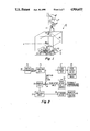
- FIG. 2 is a block diagram of the embodiment of FIG. 1;
- FIG. 3 is a plot of roll error history of a typical communication satellite using an under-sized roll control magnetic torquer
- FIG. 4 is a plot of the roll error history of the same satellite and same undersized magnetic torquer as in FIG. 3 with the pivoted momentum wheel according to the present invention
- FIG. 5 is a plot of the pivot angle of the momentum wheel to achieve the reduced roll error history of FIG. 4;
- FIG. 6 is a flowchart of the pivot control logic in accordance with one embodiment of the present invention.
- FIG. 7 is a flowchart of the pivot control logic in accordance with another embodiment of the present invention wherein the pivoted wheel enhancement also provides nutation damping;
- FIGS. 8 and 9 illustrate the trajectory of the spacecraft's body-fixed pitch axis projected on the inertially-fixed yaw/roll plane when performing corrections where the initial precession error exceeds the nutation error, and where the nutation error exceeds the precession error, respectively.
- FIG. 1 illustrates spacecraft 10 having reference axes X, Y, and Z. These axes form an orthogonal right-handed coordinate system fixed in the spacecraft's body and centered at the center of mass 10a.
- the Z axis is nominally parallel to the spacecraft's total angular momentum vector H when the spacecraft is in its intended attitude.
- a momentum wheel or rotor 13 is aligned so that its angular momentum vector is nominally parallel to the Z axis.
- a motor 15 couples the stabilized platform or body 11, which may contain an antenna or other payload, and the spinning momentum wheel 13. The rotational speed of motor 15 is controlled so that the momentum stored by wheel 13 is sufficient to provide gyroscopic stiffness to the satellite 10.
- the motor speed is also controlled to maintain the body or platform 11 so that the antenna on one face is pointing in the desired direction (for example, towards earth).
- This control action nominally maintains the X-axis in the plane defined by the local vertical and the orbit normal. As such, in a geosynchronous orbit, the platform 11 rotates once per day.
- This control is provided by a pitch control system, as described, for example, in U.S. Pat. Nos. 3,695,554 and 3,830,447 of Kevin Phillips, incorporated herein by reference.
- the momentum wheel 13 which is nominally aligned with its angular momentum vector parallel to the Z axis, is pivoted by a hinge mechanism parallel to the Y axis. This pivot allows the wheel's angular momentum vector to be moved within the plane defined by the X and Z axes.
- the wheel 13 is mounted on rotor 17 of motor 15.
- the stator of motor 15 is mounted to member 19 which is attached to platform 11 via a hinge 21.
- Hinge 21 lies on and pivots about the Y' axis, which is parallel to the Y axis.
- pivoting wheel 13 does not change the total momentum of spacecraft 10, but moves the wheel's angular momentum vector with respect to spacecraft 10 thereby transferring momentum between axes.
- Magnetic torquing produces a net change (a secular change) in the total momentum of spacecraft 10 and thus may "unload” excess momentum as well as correct attitude errors.
- a sensor 23 senses angular motion about an axis parallel to the Y axis.
- the sensor may, for example, be a typical horizon sensor that is sensitive to the infrared characteristics of the planet's horizon and produces a signal that is proportional to the satellite's roll attitude error, or it may be another type of earth sensor.
- a more detailed description of a horizon sensor can be had by reviewing U.S. Pat. No. 4,062,509 of Muhlfelder, incorporated herein by reference.
- the roll attitude error detected by the sensor 23 passes through a smoothing logic 25 (FIG. 2).
- the output from the smoothing logic 25 passes to pivot control logic 27 and also to summing circuit 34.
- the output from the summing circuit 34 is delayed by circuit 35.
- the delayed output of circuit 35 passes through threshold circuit 37 that operates the roll torquer driver 39 for energizing the magnetic torquing coil 40 in accordance with prior-art-magnetic-torquing as discussed in the above-cited U.S. Pat. No. 3,834,653.
- the torquing coil may have a skewed dipole (e.g., as represented by the arrow 70) as discussed in U.S. Pat. No.
- Circuit 35 delays the magnetic torquing for a fraction of the nutation period. This delay shifts the phase of the torque to decrease the nutation, as described in U.S. Pat. No. 4,424,948 of Muhlfelder et al., incorporated by reference herein.
- Coil 40 applies a correcting torque via interaction with the ambient magnetic field.
- This magnetic control system consisting of the earth sensor assembly, the smoothing logic, the damping delay, the threshold circuit, torque driver and magnetic torquer, is described in the above-cited U.S. Pat. No. 4,424,948.
- a magnetic torquer must be sized to accommodate the worst-case condition, i.e. the sum of the maximums of each disturbance torque in conjunction with the minimum environmental magnetic field. This requires a large magnetic coil that provides a large magnetic dipole, and so will be heavy and will consume substantial electrical power, all of which are undesirable.
- Pivot control logic 27 may include a threshold circuit having a threshold that is greater than that of threshold circuit 37, whereby wheel pivoting will serve only to limit the attitude control error.
- the pivot control logic 27 includes a microprocessor that determines when control is needed and then generates control signals. These signals are commands to a stepper motor 29 that mechanically links (represented by dashed lines 30 in FIG. 1) the satellite body 11 and the pivotable member 19 on which motor 15 and wheel 13 are mounted.
- the stepper motor 29 rotates the spin axis of the momentum wheel 13 relative to the Z axis 12 of the platform 11 in steps about the Y' axis. If the roll error is positive (that is, if the spacecraft is displaced from its nominal orientation by a rotation about the positive Y axis), then the motor pivots the wheel in a positive sense about the Y' axis.
- the pivot control logic 27 generates pivot commands in pairs, the individual commands in these pairs being nominally one-half nutation period apart. Each of these commands may include a plurality of steps, but the duration of each command is typically only a small portion of the spacecraft nutation period.
- the pivot control logic 27 commands equal pivot angles for each half of a pair. For example, to correct a roll error, the microprocessor within logic 27 would command half of the required steps in the direction to reduce the error, and one-half nutation period later would command the remaining steps in the same direction. By commanding equal pivot angles with a one-half nutation period separation, the control logic 27 tends to prevent the roll control action from increasing the spacecraft's nutation.
- the pivot control logic 27 commands pairs of nominally unequal pivot angles whereby the pivot action damps nutation while correcting roll errors. The logic for both embodiments will be described below.
- each pair of steps changes the orientation of the momentum wheel axis about the satellite roll axis by ⁇ 1 + ⁇ 2 .
- This changes the roll orientation of the satellite by ⁇ 1 + ⁇ 2 in the appropriate direction to reduce the roll error sensed by the earth sensor 23.
- the pivot control logic 27, in addition to providing stepping pulses to the momentum wheel pivot stepper motor 29, also provides a related signal to a counter 28.
- This counter 28 determines the net pivot offset angle.
- This angle from counter 28 is then added to the smoothed roll error signal from logic 25 at summing circuit 34.
- the pivot offset angle is only that due to the closed loop action described above; any externally commanded pivot offset is used by the logic within counter 28 as a zero reference for calculating the pivot-offset position in the implementation described herein.
- a roll error represents an angular misalignment about the roll axis Y between the pitch axis Z and the orbit normal. If the axis of wheel 13 is initially aligned with the pitch axis Z, then the wheel's angular momentum vector would also be offset from the orbit normal.
- correction is applied in two steps as will be described below. When the two steps are completed, the roll error will be corrected and the pitch axis will be aligned with the orbit normal. The second step will return the wheel axis to its original orientation in inertial space, but it is now offset from the satellite's pitch axis.
- the counter 28 records this angular displacement, and the net displacement is added to the roll error for use by the magnetic control loop.
- the magnetic control loop acts to align the wheel's axis (and its angular momentum vector) with the orbit normal.
- the combined action of the pivot logic 27 and the magnetic control loop tends to align both the pitch axis and the wheel's spin axis with the orbit normal.
- the signal from summing circuit 34 representing the sum of the smoothed roll error and the pivot-offset angle, is delayed via delay 35 and is thresholded via circuit 37, as discussed previously, and as discussed in connection with U.S. Pat. No. 4,424,948.
- the delayed signal permits precession of the total satellite momentum vector while simultaneously damping any prevailing nutation.
- the thresholded signal generated by circuit 37 is applied with appropriate polarity to the magnetic torquer 40 via the torquer driver (39).
- the control method described above retains the advantages of magnetic attitude control (fine resolution, no mass expulsion required, high reliability, simultaneous precession control and nutation damping) while reducing the size, weight and power of the required magnetic torquer by supplementing the magnetic closed loop control with an actively pivoted momentum wheel.
- the pivoted momentum wheel temporarily stores momentum in the transverse (roll/yaw) plane, thus precluding unacceptable attitude excursions due to temporary magnetic control torque saturation. In some satellites, this approach can halve the size and weight of the magnetic torquer. Furthermore, if the environmental magnetic field temporarily weakens or reverses, the pivot action will automatically prevent attitude divergence.
- FIG. 3 shows the roll attitude history of a typical geosynchronous momentum-biased satellite that uses an "under-sized" roll control torquer alone.
- the large roll attitude excursions of FIG. 3 (caused by temporary torque saturation) are substantially reduced, as shown in FIG. 4. This is accomplished as a result of the closed loop pivot action illustrated in FIG. 5.
- the resolution per pair of pivot steps ( ⁇ 1 + ⁇ 2 ) is 0.009°
- the threshold for pivot actuation is 0.02°
- the threshold for magnetic torquing is 0.01°.
- the roll angle ⁇ is monitored until a threshold ⁇ is crossed.
- the roll angle ⁇ is recorded, i.e. stored. Nominally one-half nutation period later (known a priori), the roll angle ⁇ is again recorded.
- the precession error is the average of these two readings--averaging or summing these two readings removes the nutation component of the roll angle from the value used to initiate corrections.
- the logic 27 then commands the stepper motor 29 to pivot wheel 13 through a first angle proportional to the sum of these two readings.
- the logic 27 commands the stepper motor 29 to pivot wheel 13 through an angle equal to the first pivot angle. After a short delay to allow any transients introduced by stepper motor 29 pivoting wheel 13 to settle out, the logic 27 resumes monitoring the roll angle ⁇ . As mentioned previously, commanding two equal pivot angle changes separated by one-half the nutation period prevents the roll control action from increasing the spacecraft's nutation.
- FIG. 6 is a flowchart representing a program for the microprocessor within logic 27 for the embodiment just described.
- the microprocessor first determines (block 61) whether the absolute value of the roll error signal ⁇ equals or exceeds the threshold ⁇ for the pivot control system. If the decision is "no," no change in the pivot angle is needed and operation of the remainder of control logic 27 is bypassed. Block 61 is repeatedly executed until the decision is "yes.” Once the roll angle ⁇ exceeds threshold ⁇ , the roll error ⁇ 1 is recorded (block 62). Following a one-half nutation period (HNP) delay (block 63), the roll error ⁇ 2 is recorded again (block 64). The microprocessor then calculates (block 65) the number S of pivot steps needed to correct the precession error.
- HNP one-half nutation period
- the number of pivot steps (S) is proportional to the sum of the two recorded roll errors ( ⁇ 1 + ⁇ 2 ) and may be either positive or negative, depending on the sign of the roll error.
- a positive value of S indicates that the wheel should pivot about the positive Y' axis (see FIG. 1), and a negative value of S indicates that it should pivot in the opposite direction.
- the microprocessor commands stepper motor 29 to move and to pivot wheel 13 by S steps (block 66). Following another one-half nutation period delay (block 67), the microprocessor commands the stepper motor 29 to pivot wheel 13 by S additional steps (block 68). After another a short delay (block 69), the process is repeated.
- the roll angle is sampled again.
- the precession error is the average of the two readings taken one-half nutation period apart.
- the nutation error equals one-half the difference between these two readings. Note that it may not be necessary to perform the division operations described in the preceding two sentences because precession error is proportional to the sum of the to readings and nutation error is proportional to their difference.
- the system uses the two readings to calculate the number of pivot steps S P required to pivot wheel 13 so as to correct the precession error, and the number of pivot steps S N required to correct the nutation error. To compensate for the entire error within one control cycle, each of the two control pivot angles should be made to equal one-half the precession and nutation errors.
- the stepper motor 29 pivots wheel 13 through an angle proportional to the sum of the precession and nutation pivot angles (S P +S N ).
- S P +S N the wheel is pivoted again-- this time through an angle proportional to the difference between the precession and nutation pivot angles (S P -S N ).
- a full control cycle takes between 1 and 11/2 nutation periods to complete.
- both large and small errors can be corrected within a single control cycle.
- gain errors, pivot angle limits, timing errors, sensor noise and other practical limitations can increase the time needed in practice to correct large errors to several nutation cycles. This is still a much faster response than is possible with the magnetic torquer yaw/roll control system.
- the pivot resolution is limited by the step size of stepper motor 29.
- the magnetic control system is much slower, its lower threshold and lower corrective torque generally provide finer control and more complete nutation damping.
- the pivot control system provides a supplemental action that rapidly corrects large errors by temporarily storing transverse momentum in a pivoted wheel 13.
- the flowchart of FIG. 7 represents a microprocessor program for the combined precession and nutation control whose operation was just described.
- the microprocessor first determines (block 81) whether the absolute value of the roll angle error signal ⁇ exceeds the threshold ⁇ for the pivot control system. If the decision is "no,” the remainder of control logic 27 is bypassed and the system waits and monitors subsequent error signals. If the decision is "yes,” as represented by the arrow at the right of block 81, the roll error ⁇ is recorded and two timers are reset to zero (block 82).
- the control system is reset as represented by the "no" output from block 83 and the process begins anew. If the roll angle ⁇ does not equal zero, and the sign does not change ("yes" arrow from block 83), the decision logic (block 85) determines if the current roll angle ⁇ exceeds the previous peak roll angle ⁇ 1 . If the new roll angle ⁇ exceeds the previously stored peak roll angle ⁇ 1 the new peak roll angle is stored and the one-half nutation period timer T H is reset (block 86).
- Block 87 measures the time T Q since crossing the threshold and the time T H since reaching the peak (block 87). When one-quarter of a nutation period has passed since the threshold was crossed, as represented by the arrow labelled “yes" leading from block 89, the system stops monitoring the roll angle. If not, as represented by the "no" arrow from block 89, then the roll angle error continues to be monitored by block 83 via a delay (block 90). When the time T H since the recorded peak equals or exceeds one-half nutation period, as represented by the arrow labelled "yes” leading from block 92, the roll error angle ⁇ 2 is sampled and stored (block 94). If not ("no" arrow from block 92), the time is updated (blocks 91, 93).
- the number of precession pivoting steps (S P ) is then calculated in proportion to the sum of the peak roll angle ⁇ 1 and the roll angle ⁇ 2 one-half nutation cycle after reaching the peak (block 95).
- the number of nutation pivoting steps S N is calculated in proportion to the difference between the two roll angles ( ⁇ 1 - ⁇ 2 ) (block 95).
- the stepper motor 29 is then stepped by the sum of the precession and nutation pivot steps, (block 96) to pivot wheel 13 by S P +S N steps. After a one-half nutation period delay (block 97), the stepper motor 29 is stepped by the difference between the precession pivot steps S P and the nutation pivot steps S N (block 98) to pivot wheel 13 by S P -S N steps. Following a delay 99 the procedure is repeated.
- pivot control logic 27 represented by the flow charts of FIGS. 6 and 7 could also be used without the magnetic control subsystem, i.e., by using only blocks 23, 25, 27 and 29 of FIG. 2.
- FIGS. 8 and 9 show the trajectory of the tip of the spacecraft's body-fixed pitch axis projected on the inertially-fixed yaw/roll plane.
- the nominal trajectory no precession error and no nutation
- the nominal trajectory is simply equilibrium point c.
- the trajectory is equilibrium point a.
- the trajectory is a circular path, A, centered on a.
- this nutational motion will be prograde (counterclockwise).
- the projected pitch axis travels completely around this circular path A once every nutation cycle.
- FIGS. 8 and 9 represent the results of perfect pivot control. Although the actual performance will be similar to that depicted in FIGS. 8 and 9, in practice there will be some residual error that must be removed in one or more subsequent control cycles. For FIG. 8, the initial precession error exceeds the nutation error. For FIG. 9, this relationship is reversed.
- the roll error is greatest when the projected pitch axis is at point d on trajectory A. This is the peak error detected by the preferred pivot control logic 27 (FIG. 7).
- the pivot control action takes place half a nutation cycle later, when the projected pitch axis is at point e at which the first pivoting of wheel 13 occurs. This first pivoting reduces both the nutation and precession errors.
- the trajectory is circular path B, centered on point b.
- One-half a nutation cycle after the first pivoting the projected pitch axis is at point c.
- the spacecraft's body-fixed pitch axis is parallel to the inertial pitch axis. This is the target attitude, and the second pivoting of wheel 13 occurs at this point.
- the second pivoting reduces both the nutation and precession errors essentially to zero and the final trajectory is point c.
Abstract
Description
Claims (21)
Priority Applications (3)
| Application Number | Priority Date | Filing Date | Title |
|---|---|---|---|
| US07/207,560 US4916622A (en) | 1988-06-16 | 1988-06-16 | Attitude control system |
| DE3918832A DE3918832C2 (en) | 1988-06-16 | 1989-06-09 | Attitude control arrangement for a spacecraft |
| JP1150689A JP2567098B2 (en) | 1988-06-16 | 1989-06-15 | Attitude control system |
Applications Claiming Priority (1)
| Application Number | Priority Date | Filing Date | Title |
|---|---|---|---|
| US07/207,560 US4916622A (en) | 1988-06-16 | 1988-06-16 | Attitude control system |
Publications (1)
| Publication Number | Publication Date |
|---|---|
| US4916622A true US4916622A (en) | 1990-04-10 |
Family
ID=22771086
Family Applications (1)
| Application Number | Title | Priority Date | Filing Date |
|---|---|---|---|
| US07/207,560 Expired - Lifetime US4916622A (en) | 1988-06-16 | 1988-06-16 | Attitude control system |
Country Status (3)
| Country | Link |
|---|---|
| US (1) | US4916622A (en) |
| JP (1) | JP2567098B2 (en) |
| DE (1) | DE3918832C2 (en) |
Cited By (16)
| Publication number | Priority date | Publication date | Assignee | Title |
|---|---|---|---|---|
| US5107434A (en) * | 1990-04-19 | 1992-04-21 | General Electric Company | Three-axis spacecraft attitude control using polar star sensor |
| US5123617A (en) * | 1990-03-05 | 1992-06-23 | General Electric Company | Spacecraft momentum unloading using controlled magnetic torques |
| US5142931A (en) * | 1991-02-14 | 1992-09-01 | Honeywell Inc. | 3 degree of freedom hand controller |
| US5182961A (en) * | 1991-07-30 | 1993-02-02 | Honeywell Inc. | Three degree of freedom translational axis hand controller mechanism |
| US5279483A (en) * | 1990-12-21 | 1994-01-18 | Aerospatiale Societe Nationale Industrielle | Attitude control system for a three-axis stabilized satellite especially a remote sensing satellite |
| US5459669A (en) * | 1994-02-14 | 1995-10-17 | Space Systems/Loral, Inc. | Control system and method for spacecraft attitude control |
| US5540405A (en) * | 1991-11-27 | 1996-07-30 | Hughes Aircraft Company | Method and apparatus for compensating for magnetic disturbance torques on a satellite |
| US5646761A (en) * | 1993-09-24 | 1997-07-08 | Jolt. Ltd. | Wireless communication system |
| US5826829A (en) * | 1996-07-15 | 1998-10-27 | Space Systems/Loral Inc. | Spacecraft control system with a trihedral momentum bias wheel configuration |
| US5957410A (en) * | 1995-06-09 | 1999-09-28 | Daimler-Benz Aerospace Ag | Earth oriented satellite and process for controlling the position, nutation and spin |
| US20100019092A1 (en) * | 2008-07-23 | 2010-01-28 | Liu Dan Y | Systems and method of controlling a spacecraft using attitude sensors |
| CN103523243A (en) * | 2013-10-12 | 2014-01-22 | 上海新跃仪表厂 | Non-biased momentum single-flywheel magnetizing control method |
| CN106184820A (en) * | 2016-08-10 | 2016-12-07 | 西北工业大学 | A kind of combination drives many moment leaving momentum wheel and control method thereof |
| CN112607064A (en) * | 2020-12-25 | 2021-04-06 | 上海交通大学 | Micro-nano satellite magnetic damping control method for avoiding entering spinning state |
| CN112902768A (en) * | 2021-03-18 | 2021-06-04 | 星河动力(北京)空间科技有限公司 | Control method and device for carrier rocket rolling, carrier rocket and storage medium |
| US11279501B2 (en) * | 2018-10-25 | 2022-03-22 | General Atomics | Satellite attitude control system using eigen vector, non-linear dynamic inversion, and feedforward control |
Families Citing this family (2)
| Publication number | Priority date | Publication date | Assignee | Title |
|---|---|---|---|---|
| DE4007497A1 (en) * | 1990-03-09 | 1991-09-12 | Messerschmitt Boelkow Blohm | Space station position control arrangement - contains electrically-driven reaction wheels and pivotable magnetic moment controllers for compensating disturbance moments |
| DE4129628A1 (en) * | 1991-09-06 | 1993-03-18 | Deutsche Aerospace | METHOD AND DEVICE FOR CONTROLLING THE POSITION OF A THREE-AXIS-STABILIZED SPIRAL VEHICLE |
Citations (18)
| Publication number | Priority date | Publication date | Assignee | Title |
|---|---|---|---|---|
| US3643897A (en) * | 1968-10-18 | 1972-02-22 | Communications Satellite Corp | Nutation correction system for spin-stabilized satellite |
| US3695554A (en) * | 1970-10-16 | 1972-10-03 | Rca Corp | Nutation damping in dual-spin spacecraft |
| US3813067A (en) * | 1972-06-29 | 1974-05-28 | Trw Inc | Attitude stabilization system |
| US3830447A (en) * | 1972-09-28 | 1974-08-20 | Rca Corp | Active nutation damping in dual-spin spacecraft |
| US3834653A (en) * | 1972-03-27 | 1974-09-10 | Rca Corp | Closed loop roll and yaw control for satellites |
| US3937423A (en) * | 1974-01-25 | 1976-02-10 | Hughes Aircraft Company | Nutation and roll error angle correction means |
| US3984071A (en) * | 1974-08-29 | 1976-10-05 | Trw Inc. | Satellite nutation attenuation apparatus |
| US4062509A (en) * | 1975-07-21 | 1977-12-13 | Rca Corporation | Closed loop roll/yaw control system for satellites |
| US4084773A (en) * | 1975-09-15 | 1978-04-18 | Rca Corporation | Magnetic control of spacecraft roll disturbance torques |
| US4114841A (en) * | 1977-02-22 | 1978-09-19 | Rca Corporation | Magnetic torquing system for changing the spin rate of an orbiting satellite |
| GB1549544A (en) * | 1976-09-17 | 1979-08-08 | Matra | Attitude control systems for space vehicles |
| US4230294A (en) * | 1979-07-23 | 1980-10-28 | Rca Corporation | Closed loop roll control for momentum biased satellites |
| US4288051A (en) * | 1976-09-18 | 1981-09-08 | Messerschmitt-Bolkow-Blohm Gesellschaft Mit Beschrankter Haftung | Method and apparatus for controlling a satellite |
| US4370716A (en) * | 1979-01-23 | 1983-01-25 | Matra | Active nutation control system for space vehicle |
| GB2121984A (en) * | 1982-04-20 | 1984-01-04 | Messerschmitt Boelkow Blohm | Method of and equipment for adjusting the position of an earth satellite |
| US4424948A (en) * | 1981-01-22 | 1984-01-10 | Rca Corporation | Magnetically torqued nutation damping |
| US4521855A (en) * | 1981-07-27 | 1985-06-04 | Ford Aerospace & Communications Corporation | Electronic on-orbit roll/yaw satellite control |
| US4728062A (en) * | 1985-11-12 | 1988-03-01 | Rca Corporation | Pivot actuated nutation damping for a dual-spin spacecraft |
-
1988
- 1988-06-16 US US07/207,560 patent/US4916622A/en not_active Expired - Lifetime
-
1989
- 1989-06-09 DE DE3918832A patent/DE3918832C2/en not_active Expired - Fee Related
- 1989-06-15 JP JP1150689A patent/JP2567098B2/en not_active Expired - Lifetime
Patent Citations (18)
| Publication number | Priority date | Publication date | Assignee | Title |
|---|---|---|---|---|
| US3643897A (en) * | 1968-10-18 | 1972-02-22 | Communications Satellite Corp | Nutation correction system for spin-stabilized satellite |
| US3695554A (en) * | 1970-10-16 | 1972-10-03 | Rca Corp | Nutation damping in dual-spin spacecraft |
| US3834653A (en) * | 1972-03-27 | 1974-09-10 | Rca Corp | Closed loop roll and yaw control for satellites |
| US3813067A (en) * | 1972-06-29 | 1974-05-28 | Trw Inc | Attitude stabilization system |
| US3830447A (en) * | 1972-09-28 | 1974-08-20 | Rca Corp | Active nutation damping in dual-spin spacecraft |
| US3937423A (en) * | 1974-01-25 | 1976-02-10 | Hughes Aircraft Company | Nutation and roll error angle correction means |
| US3984071A (en) * | 1974-08-29 | 1976-10-05 | Trw Inc. | Satellite nutation attenuation apparatus |
| US4062509A (en) * | 1975-07-21 | 1977-12-13 | Rca Corporation | Closed loop roll/yaw control system for satellites |
| US4084773A (en) * | 1975-09-15 | 1978-04-18 | Rca Corporation | Magnetic control of spacecraft roll disturbance torques |
| GB1549544A (en) * | 1976-09-17 | 1979-08-08 | Matra | Attitude control systems for space vehicles |
| US4288051A (en) * | 1976-09-18 | 1981-09-08 | Messerschmitt-Bolkow-Blohm Gesellschaft Mit Beschrankter Haftung | Method and apparatus for controlling a satellite |
| US4114841A (en) * | 1977-02-22 | 1978-09-19 | Rca Corporation | Magnetic torquing system for changing the spin rate of an orbiting satellite |
| US4370716A (en) * | 1979-01-23 | 1983-01-25 | Matra | Active nutation control system for space vehicle |
| US4230294A (en) * | 1979-07-23 | 1980-10-28 | Rca Corporation | Closed loop roll control for momentum biased satellites |
| US4424948A (en) * | 1981-01-22 | 1984-01-10 | Rca Corporation | Magnetically torqued nutation damping |
| US4521855A (en) * | 1981-07-27 | 1985-06-04 | Ford Aerospace & Communications Corporation | Electronic on-orbit roll/yaw satellite control |
| GB2121984A (en) * | 1982-04-20 | 1984-01-04 | Messerschmitt Boelkow Blohm | Method of and equipment for adjusting the position of an earth satellite |
| US4728062A (en) * | 1985-11-12 | 1988-03-01 | Rca Corporation | Pivot actuated nutation damping for a dual-spin spacecraft |
Non-Patent Citations (14)
| Title |
|---|
| "High Pointing Accuracy with a Momentum Bias Attitude Control System", J. Guidance and Control, vol. 3, No. 3, May-Jun. 1980, Article No. 78-569R, pp. 195-202, by K. L. Lebsock. |
| "Magnetotorquing for the Attitude Control of Geostationary Satellites", Proc. of AOCS Conference, Noordwijk, The Netherlands, Oct. 3-6, 1977, ESA SP 128, pp. 103-110, by J. L. Lacombe. |
| "Optimum Antenna Beam Pointing for Communication Satellites", AIAA 11th Communication Satellite Systems Conf., Mar. 17-20, 1986, San Diego, CA, Article No. AIAA-86-0613-CP, pp. 70-78, by J. E. Keigler et al. |
| "Satellite Attitude Control with a Gimbaled Reaction Wheel Digital Control System", Automatica, vol. 8, pp. 9-21, by C. H. Much et al. |
| "Satellite Earth-Pointing Attitude Control in the Absence of Yaw Sensing, Using a Double-Gimballed Momentum Wheel", J. British Interplanetary Society, vol. 27, pp. 443-458, 1974, by W. G. Hughes. |
| "The Application of Magnetic Attitude Control to a Momentum-Biased, Synchronous Communications Satellite", AIAA Guidance and Control Conf., Boston, MA, Aug. 20-22, 1975, by G. E. Schmidt, Jr. |
| "Three Axis Attitude Control of a Synchronous Communications Satellite", AIAA 3rd Communications Satellite System Conf., Los Angeles, CA, Apr. 6-8, 1970, Paper No. 70-456, pp. 1-7, J. U. Beusch et al. |
| High Pointing Accuracy with a Momentum Bias Attitude Control System , J. Guidance and Control, vol. 3, No. 3, May Jun. 1980, Article No. 78 569R, pp. 195 202, by K. L. Lebsock. * |
| Magnetotorquing for the Attitude Control of Geostationary Satellites , Proc. of AOCS Conference, Noordwijk, The Netherlands, Oct. 3 6, 1977, ESA SP 128, pp. 103 110, by J. L. Lacombe. * |
| Optimum Antenna Beam Pointing for Communication Satellites , AIAA 11th Communication Satellite Systems Conf., Mar. 17 20, 1986, San Diego, CA, Article No. AIAA 86 0613 CP, pp. 70 78, by J. E. Keigler et al. * |
| Satellite Attitude Control with a Gimbaled Reaction Wheel Digital Control System , Automatica, vol. 8, pp. 9 21, by C. H. Much et al. * |
| Satellite Earth Pointing Attitude Control in the Absence of Yaw Sensing, Using a Double Gimballed Momentum Wheel , J. British Interplanetary Society, vol. 27, pp. 443 458, 1974, by W. G. Hughes. * |
| The Application of Magnetic Attitude Control to a Momentum Biased, Synchronous Communications Satellite , AIAA Guidance and Control Conf., Boston, MA, Aug. 20 22, 1975, by G. E. Schmidt, Jr. * |
| Three Axis Attitude Control of a Synchronous Communications Satellite , AIAA 3rd Communications Satellite System Conf., Los Angeles, CA, Apr. 6 8, 1970, Paper No. 70 456, pp. 1 7, J. U. Beusch et al. * |
Cited By (19)
| Publication number | Priority date | Publication date | Assignee | Title |
|---|---|---|---|---|
| US5123617A (en) * | 1990-03-05 | 1992-06-23 | General Electric Company | Spacecraft momentum unloading using controlled magnetic torques |
| US5107434A (en) * | 1990-04-19 | 1992-04-21 | General Electric Company | Three-axis spacecraft attitude control using polar star sensor |
| US5279483A (en) * | 1990-12-21 | 1994-01-18 | Aerospatiale Societe Nationale Industrielle | Attitude control system for a three-axis stabilized satellite especially a remote sensing satellite |
| US5142931A (en) * | 1991-02-14 | 1992-09-01 | Honeywell Inc. | 3 degree of freedom hand controller |
| US5182961A (en) * | 1991-07-30 | 1993-02-02 | Honeywell Inc. | Three degree of freedom translational axis hand controller mechanism |
| US5540405A (en) * | 1991-11-27 | 1996-07-30 | Hughes Aircraft Company | Method and apparatus for compensating for magnetic disturbance torques on a satellite |
| US5646761A (en) * | 1993-09-24 | 1997-07-08 | Jolt. Ltd. | Wireless communication system |
| US5459669A (en) * | 1994-02-14 | 1995-10-17 | Space Systems/Loral, Inc. | Control system and method for spacecraft attitude control |
| US5957410A (en) * | 1995-06-09 | 1999-09-28 | Daimler-Benz Aerospace Ag | Earth oriented satellite and process for controlling the position, nutation and spin |
| US5826829A (en) * | 1996-07-15 | 1998-10-27 | Space Systems/Loral Inc. | Spacecraft control system with a trihedral momentum bias wheel configuration |
| US20100019092A1 (en) * | 2008-07-23 | 2010-01-28 | Liu Dan Y | Systems and method of controlling a spacecraft using attitude sensors |
| US8620496B2 (en) | 2008-07-23 | 2013-12-31 | The Boeing Company | Systems and method of controlling a spacecraft using attitude sensors |
| CN103523243A (en) * | 2013-10-12 | 2014-01-22 | 上海新跃仪表厂 | Non-biased momentum single-flywheel magnetizing control method |
| CN103523243B (en) * | 2013-10-12 | 2015-12-02 | 上海新跃仪表厂 | Not offset momentum single flywheel adds magnetic control method |
| CN106184820A (en) * | 2016-08-10 | 2016-12-07 | 西北工业大学 | A kind of combination drives many moment leaving momentum wheel and control method thereof |
| US11279501B2 (en) * | 2018-10-25 | 2022-03-22 | General Atomics | Satellite attitude control system using eigen vector, non-linear dynamic inversion, and feedforward control |
| CN112607064A (en) * | 2020-12-25 | 2021-04-06 | 上海交通大学 | Micro-nano satellite magnetic damping control method for avoiding entering spinning state |
| CN112902768A (en) * | 2021-03-18 | 2021-06-04 | 星河动力(北京)空间科技有限公司 | Control method and device for carrier rocket rolling, carrier rocket and storage medium |
| CN112902768B (en) * | 2021-03-18 | 2022-09-09 | 星河动力(北京)空间科技有限公司 | Carrier rocket rolling control method and device, carrier rocket and storage medium |
Also Published As
| Publication number | Publication date |
|---|---|
| JPH0245299A (en) | 1990-02-15 |
| DE3918832A1 (en) | 1989-12-21 |
| DE3918832C2 (en) | 1996-02-08 |
| JP2567098B2 (en) | 1996-12-25 |
Similar Documents
| Publication | Publication Date | Title |
|---|---|---|
| US4916622A (en) | Attitude control system | |
| US5984236A (en) | Momentum unloading using gimbaled thrusters | |
| EP0769736B1 (en) | Method for inclined orbit attitude control for momentum bias spacecraft | |
| US5149022A (en) | Satellite roll and yaw attitude control method | |
| US6481672B1 (en) | Gimbaled thruster control system | |
| US5349532A (en) | Spacecraft attitude control and momentum unloading using gimballed and throttled thrusters | |
| US6296207B1 (en) | Combined stationkeeping and momentum management | |
| EP0434861B1 (en) | Attitude pointing error correction system and method for geosynchronous satellites | |
| US4230294A (en) | Closed loop roll control for momentum biased satellites | |
| US5765780A (en) | Systematic vectored thrust calibration method for satellite momentum control | |
| US5058835A (en) | Wheel speed management control system for spacecraft | |
| US5459669A (en) | Control system and method for spacecraft attitude control | |
| US7654490B2 (en) | Precision attitude control system for gimbaled thruster | |
| CA1183241A (en) | Magnetically torqued nutation damping | |
| US4728062A (en) | Pivot actuated nutation damping for a dual-spin spacecraft | |
| US5906339A (en) | Multiple axis solar sailing | |
| US5957411A (en) | Method using double thruster firings to deadbeat flexible solar array structural oscillations | |
| US6471161B1 (en) | Satellite attitude control system | |
| US5984237A (en) | Delta-V targeting system for three-axis controlled spacecraft | |
| EP0932549B1 (en) | Autonomous solar torque management | |
| Spencer | Automatic magnetic control of a momentum-biased observatory in equatorial orbit | |
| Ratan et al. | Directed momentum management for rotating spacecraft | |
| Muhlfelder | Attitude control system performance of RCA Satcom | |
| Barker et al. | Three axis authority momentum spacecraft attitude control | |
| Schmeichel | TDRS ANTENNA AUTOTRACK LOOP |
Legal Events
| Date | Code | Title | Description |
|---|---|---|---|
| AS | Assignment |
Owner name: GENERAL ELECTRIC COMPANY, A CORP. OF NEW YORK Free format text: ASSIGNMENT OF ASSIGNORS INTEREST.;ASSIGNORS:RAMAN, KIDAMBI V.;MUHLFELDER, LUDWIG;HUBERT, CARL H.;AND OTHERS;REEL/FRAME:004935/0319 Effective date: 19880607 |
|
| STCF | Information on status: patent grant |
Free format text: PATENTED CASE |
|
| FEPP | Fee payment procedure |
Free format text: PAYOR NUMBER ASSIGNED (ORIGINAL EVENT CODE: ASPN); ENTITY STATUS OF PATENT OWNER: LARGE ENTITY |
|
| FPAY | Fee payment |
Year of fee payment: 4 |
|
| AS | Assignment |
Owner name: MARTIN MARIETTA CORPORATION, MARYLAND Free format text: ASSIGNMENT OF ASSIGNORS INTEREST;ASSIGNOR:GENERAL ELECTRIC COMPANY;REEL/FRAME:007046/0736 Effective date: 19940322 |
|
| AS | Assignment |
Owner name: LOCKHEED MARTIN CORPORATION, MARYLAND Free format text: ASSIGNMENT OF ASSIGNORS INTEREST;ASSIGNOR:MARTIN MARIETTA CORPORATION;REEL/FRAME:008628/0518 Effective date: 19960128 |
|
| FPAY | Fee payment |
Year of fee payment: 8 |
|
| FEPP | Fee payment procedure |
Free format text: PAYOR NUMBER ASSIGNED (ORIGINAL EVENT CODE: ASPN); ENTITY STATUS OF PATENT OWNER: LARGE ENTITY |
|
| FEPP | Fee payment procedure |
Free format text: PAYER NUMBER DE-ASSIGNED (ORIGINAL EVENT CODE: RMPN); ENTITY STATUS OF PATENT OWNER: LARGE ENTITY |
|
| FPAY | Fee payment |
Year of fee payment: 12 |