US4917255A - Collapsible container - Google Patents
Collapsible container Download PDFInfo
- Publication number
- US4917255A US4917255A US07/315,478 US31547889A US4917255A US 4917255 A US4917255 A US 4917255A US 31547889 A US31547889 A US 31547889A US 4917255 A US4917255 A US 4917255A
- Authority
- US
- United States
- Prior art keywords
- walls
- disposed
- wall
- container
- base
- Prior art date
- Legal status (The legal status is an assumption and is not a legal conclusion. Google has not performed a legal analysis and makes no representation as to the accuracy of the status listed.)
- Expired - Lifetime
Links
Images


Classifications
-
- B—PERFORMING OPERATIONS; TRANSPORTING
- B65—CONVEYING; PACKING; STORING; HANDLING THIN OR FILAMENTARY MATERIAL
- B65D—CONTAINERS FOR STORAGE OR TRANSPORT OF ARTICLES OR MATERIALS, e.g. BAGS, BARRELS, BOTTLES, BOXES, CANS, CARTONS, CRATES, DRUMS, JARS, TANKS, HOPPERS, FORWARDING CONTAINERS; ACCESSORIES, CLOSURES, OR FITTINGS THEREFOR; PACKAGING ELEMENTS; PACKAGES
- B65D25/00—Details of other kinds or types of rigid or semi-rigid containers
- B65D25/005—Side walls formed with an aperture or a movable portion arranged to allow removal or insertion of contents
-
- B—PERFORMING OPERATIONS; TRANSPORTING
- B65—CONVEYING; PACKING; STORING; HANDLING THIN OR FILAMENTARY MATERIAL
- B65D—CONTAINERS FOR STORAGE OR TRANSPORT OF ARTICLES OR MATERIALS, e.g. BAGS, BARRELS, BOTTLES, BOXES, CANS, CARTONS, CRATES, DRUMS, JARS, TANKS, HOPPERS, FORWARDING CONTAINERS; ACCESSORIES, CLOSURES, OR FITTINGS THEREFOR; PACKAGING ELEMENTS; PACKAGES
- B65D11/00—Containers having bodies formed by interconnecting or uniting two or more rigid, or substantially rigid, components made wholly or mainly of plastics material
- B65D11/18—Containers having bodies formed by interconnecting or uniting two or more rigid, or substantially rigid, components made wholly or mainly of plastics material collapsible, i.e. with walls hinged together or detachably connected
- B65D11/1833—Containers having bodies formed by interconnecting or uniting two or more rigid, or substantially rigid, components made wholly or mainly of plastics material collapsible, i.e. with walls hinged together or detachably connected whereby all side walls are hingedly connected to the base panel
Definitions
- the invention relates to containers of the type used for packaging, shipping and inventoring goods in bulk. More specifically the invention relates to containers which are collapsible after they have been emptied and stackable in either their collapsed or upright positions in order to reduce the spaced required for them to be shipped or stored.
- collapsible containers of the subject invention are often employed directly adjacent the assembly process. More specifically, many times erected upright containers are disposed in close proximity to each other on a conveyor means adjacent the end of an assembly line for receiving newly manufactured goods or at a point along the assembly process and containing inventory or work in process. Further, collapsible containers are often disposed in close proximity to each other during shipping and at other times.
- a problem arises in moving the side walls from an upright position to a collapsed position when a container becomes empty but is still in close proximity or adjacent another container. This is because, typically in the prior art, latches are disposed on the side walls and accessible only from the outside of the container for releasing the latches to allow the walls to collapse. When the containers are closely juxtaposed with respect to one another, it is very difficult to disengage the latches.
- the subject invention overcomes all of these deficiencies in the prior art in a very durable, relatively light weight and extremely versatile collapsible container.
- the subject invention is directed toward a collapsible container assembly including a base having a plurality of sides, a pair of side walls and a pair of end walls with each of the walls adapted to be extended vertically upward from a side of the base to define an interior portion of the container.
- the assembly also includes wall hinge means interconnecting each of the side and end walls to the base and moveably supporting the walls as the walls are moved between a collapsed position to an upright position.
- the base includes a rigid portion forming the bottom of the container with the rigid portion being made of one material and reinforced with another material for strengthening the base of the container.
- the assembly also includes hinge means interconnecting each of the side and end walls to the base and movably supporting the walls as they are moved between a collapsed position to an upright position.
- the hinge means are disposed and each wall is specifically configured to securely and efficiently nest when the container is in the collapsed position.
- the assembly further includes wall latching means for releasably latching adjacent side and end walls together when the side and end walls are in the upright position.
- the wall latching means includes a latch member movable between latched and unlatched positions and also includes a means disposed on the interior of the container for moving the latch member to the unlatched position.
- the subject invention includes a locking means on adjacent side an end walls for providing interlocking engagement therebetween when the walls are in the upright position and are specifically adapted for allowing the adjacent side and walls to be rapidly removed from the collapsed to the upright position and efficiently nesting so as to preclude relative movement therebetween.
- the subject invention overcomes the problems of the prior art by including a collapsible container assembly with a very strong base and side walls which are specifically constructed for efficient nesting when the walls are in a collapsed condition and which may support large loads when stacked.
- the container of the subject invention further overcomes the problems in the prior art by including wall latching means which are specifically adapted to release the latches from the inside of the container allowing the container to be collapsed even when it is juxtaposed in close proximity to another containers.
- the collapsible container of the subject invention includes locking means on adjacent side and end walls which preclude relative movement between adjacent side and end walls in a manner superior to the prior art.
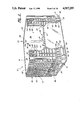
- FIG. 1 is a perspective view of the container with the walls in a vertically locked position
- FIG. 2 is perspective view wherein a door in a side wall has been unlocked and folded outward;
- FIG. 3 is a partially broken away perspective view of a corner of the container
- FIG. 3a is a cross-sectional view taken substantially along lines 3a--3a of FIG. 3;
- FIG. 4 is a perspective view of the underside of the base of the container
- FIG. 5 is an enlarged exploded view of the hinge means of the subject invention.
- FIG. 6 is a cross-sectional view taken substantially along lines 6--6 of FIG. 5;
- FIG. 7 is a cross-sectional view taken substantially along lines 7--7 of FIG. 5;
- FIG. 8 is a cross-sectional view taken substantially along lines 8--8 of FIG. 5.
- FIG. 9 is an enlarged elevational view of the wall latching means in the latched position
- FIG. 10 is an enlarged plan view of the wall latching means with adjacent side and end walls latched in the vertical position
- FIG. 11 is an enlarged top view of the door latching means with the door latched in the vertical closed position
- FIG. 12 is a side view of the container when the walls are in the collapsed position
- FIG. 13 is a side view of the container when the walls are in the collapsed position
- FIG. 14 is a perspective view of the container when the walls are in the collapse position
- a collapsible container assembly of the subject invention is generally indicated at 10 in FIGS. 1 and 2.
- the container assembly 10 includes a base generally indicated at 12 which has a plurality of sides generally indicated at 14.
- the assembly further includes a pair of side walls 16 and 18 and a pair of end walls 20 and 22.
- Each of the walls 16, 18, 20, 22 are adapted to be extended vertically upward from a side 14 of the base 12 to define an interior portion 24 of the container 10.
- the assembly further includes wall hinge means generally indicated at 26 interconnecting each of the side and end walls 16, 18, 20, 22 to the base 12 and movably supporting the walls 16, 18, 20, 22 as they move between a collapsed position to an upright position.
- the base 12 includes a rigid portion generally indicated at 28 forming the bottom of the container 10.
- the rigid portion may be made of one material and reinforced with another material for strengthening the base 12 of the container 10.
- the rigid portion 28 may be made of a structural foam which is reinforced by steel.
- the rigid portion 28 of the subject invention includes a plurality of longitudinal support members 30 disposed parallel and perpendicular with respect to each other to form a grid.
- the support members 30 are made of structural foam.
- a plurality of the structural foam support members 30 may include an outer perimeter 32 and an inner member 34 which may be made of steel or any other reinforcing material.
- these structural foam support members 32 may include the reinforcing member 34 for a predetermined length of the support member 32 or they may include the reinforced member 34 for their entire length.
- the rigid portion 28 includes a support member 32 disposed centrally on the rigid portion 28 and extending across the rigid portion between base sides 14 bounding the rigid portion. This centrally disposed support member 32 is reinforced by a steel reinforcing member 34 along its entire length between opposing base sides 14. Further, the rigid portion includes two more reinforcing support members 32 disposed on either side of the central support member and in parallel spaced relation to the central support member. In this way, the rigid portion 28 of the base 12 may be strengthened to effectively support the ever increasing load to which containers of the subject invention are being subjected.
- the base 12 further includes a plurality of container support means generally indicated at 36 depending from the rigid portion 28 about the periphery thereof as illustrated in FIG. 4.
- the support means 36 includes a corner support member 38 disposed at each of the four corners of the rigid portion 28 and a perimeter support member 40 disposed intermediate the pairs of corner support members 38.
- the support members 38 and 40 are similar to legs extending downwardly from the rigid portion 28 to space the rigid portion 28 from a support surface.
- Straps 42 extend between the container support means 36 and define channels 44 between predetermined container support means 36. More specifically, the straps 42 extend between the corner support members 38 and the perimeter support members 40 to define a pair of forked channels 44 on each side of the container for receiving the forks of a fork lift to facilitate the raising and lowering of the container assembly 10.
- the straps 42 also add to the structural integrity of the container 10 as the container is moved by a fork lift or stacked one upon the other.
- the straps 42 include irregular shaped surfaces 46 which border the periphery of the channels 44. Said another way, the straps 42 include a corrugated surface 46 which facilitates better heat transfer during the molding process of the structural foam container and thus reduces the occurrence of uneven cooling and "shrink" which commonly plagues the industry.
- the wall hinge means 26 includes a series of tongue and grooves along the bottom edge of the side and end walls 16, 18, 20, 22 and the top edge of the sides 14 of the base 12. More specifically, the tongues 27 of the side and end walls 16, 18, 20, 22 are disposed in the grooves 29 of the sides 14 of the base 12 and vice versa, as shown in FIG. 5.
- the wall hinge means 26 further includes a series of hinge holes or apertures generally indicated at 48 along the bottom edge of the side and end walls 16, 18, 20, 22 and the top edge of the sides 14 of the base 12 in the tongue and groove arrangement.
- a rod 50 is disposed in the apertures 48 of the side and end walls 16, 18, 20, 22 and the sides 14 of the base 12 and has a lock washer, or any other suitable means, on each end thereof to secure the tongues 27 in the grooves 29 and to allow pivotal movement of the side and end walls 16, 18, 20, 22 relative to a base 12.
- FIGS. 6, 7 and 8 illustrate the relationship between the apertures 48 and the rod 50 at various points along the tongue and groove hinge means 26. More specifically, the aperture 48 in the tongues 27 form a trough 52 including an open portion for accepting the rod 50. The open portion in at least one of the troughs 52 is disposed in a direction substantially toward the interior 24 of the container 10, as shown in FIG. 7.
- the open portion in at least one of the troughs is disposed a direction substantially away from the interior 24 defined by the container 10.
- the tongues 27 are disposed such that the open portions of adjacent tongues 27 are not disposed in the same direction.
- the side and end walls 16, 18, 20, 22 have planar interior sheets 56 and ribs generally indicated at 58 on the exterior of the side and end walls and extending outwardly therefrom in spaced relation with respect to each other.
- the ribs 58 are disposed closer to one another near the tops of the side and end walls 16, 18 and 20 and also near the base to provide greater support to the side and end walls near these areas.
- the ribs 58 include horizontal ribs 60 and vertical ribs 62. Together, the ribs 58, 60 and 62 form a support matrix for providing greater support to the side and end walls near the top of the wall and near the base 12 of the container assembly 10 and ensures the structural integrity of the assembly under various loading stresses.
- the collapsible container assembly 10 also includes locking means generally indicated at 64 disposed on adjacent side and end wall 16, 18, 20, 22 for providing interlocking engagement therebetween when the walls are in the upright position.
- the locking means 64 includes a flange 66 disposed on the side walls 16 and 18 along a substantial portion of a length thereof.
- the flange 66 includes at least one locking tab, generally indicated at 68, extending away from the interior 24 of the container 10.
- the locking tab 68 includes an outermost surface 70 disposed furthest from the interior 24 of the container 10 and first and second locking surfaces 72, 74 extending between the outermost surface 70 and the side wall 66.
- the tabs 68 further include a contact surface 76 extending between the outermost surface 70 and the side wall flange 66, and between the first and second locking surfaces 72, 74.
- the contact surface 76 forms an obtuse angle with respect to the outermost surface 70 as shown in FIG. 9.
- the locking means 64 further includes a flange 78 disposed on either side of the end walls 20 and 22 and along a substantial portion of the length thereof.
- the flanges 78 extend perpendicular to the end wall 20, 22 and include means, generally indicated at 80, disposed on the end wall flanges 78 for receiving the locking tab 68 in a snug fashion and thereby locking the walls 16, 18, 20, 22 from relative movement with respect to each other.
- the end walls 20, 22 further include a guide surface 82 disposed on the end walls 20, 22 directly adjacent the end wall flanges 78.
- the contact surface 76 on the locking tab 68 is specifically adapted for sliding frictional engagement with the guide surface 82 on the end walls 20, 22 as the side walls 16, 18 are moved from the collapsed position to the upright position. The interaction of these surfaces guide the tab 68 into locking engagement with the means 80 disposed on the end wall flanges 78 for receiving the locking tabs 68 and for preventing relative movement of the walls 16, 18, 20, 22 with respect to each other when in the upright
- the guide means 82 forms an obtuse angle with the end wall flanges 78 to facilitate the sliding frictional engagement between the contact surface 76 on the locking tab 68 and the guide surface 82 as the side walls 16, 18 are moved from the collapsed position to the upright position as shown in FIG. 9.
- This feature is an effective means to guide the tab 68 into locking engagement with the means 80 disposed on the end wall flanges 78 for receiving the locking tab 68 without requiring the operator to precisely position the adjacent side and end walls.
- the locking means 64 can include a plurality of tabs 68 disposed at predetermined spaced intervals along the side wall flanges 66 as shown in FIG. 3. Further, each of the tabs are adapted to be received by the means 80 disposed on the end wall flanges 78 in a snug fashion, thereby locking the walls 16, 18, 20, 22 from relative movement with respect to each other.
- the locking tabs 68 substantially define a delta-shaped tab.
- the means 80 disposed on the end wall flanges 78 for receiving the delta-shaped locking tabs 68 include flanges 83 extending substantially along the length of the end wall flanges 78 and inwardly toward the interior 24 defined by the container 10.
- the inwardly extending flanges present delta-shaped openings 84 disposed at predetermined positions along the end wall flanges 78 corresponding to the delta-shaped locking tabs 68 for receiving the delta-shaped tabs.
- the delta-shaped openings 84 in the inwardly extending flanges 83 include first and second stop surfaces 86, 88 for engagement with the first and second locking surfaces 72, 74 on the delta-shaped tabs 68 to prevent relative movement between the side and end walls 16, 18, 20, 22.
- the collapsible container assembly 10 of the subject invention further includes wall latching means generally indicated at 90 for releasably latching the adjacent side and end walls 16, 18, 20, 22 together when the side and end walls are in the upright position as shown in FIGS. 9 and 10.
- the wall latching means 90 includes a latch member 92 which is operatively mounted to the edge of the side walls 16, 18 by a fastening means such as a rivit 94 or the like and is movable between latched and unlatched positions.
- the wall latching means further includes means, generally indicated at 96, disposed on the interior 24 of the container 10 for moving the latch member to the unlatched position. More specifically, the means 96 is disposed on the interior planar sheet 56 of the side walls 16, 18 and includes an opening 98 disposed on the interior planar sheet 56 of the side walls 16, 18.
- the means 96 further includes an interior latch actuator 100 disposed within the opening 98 and operatively connected to the latch member 92 and adapted to move the latch member 92 to the unlatched position.
- the wall latching means 90 also includes an exterior latch actuator 102 which is also operatively connected to the latch member 92 but which is disposed on the side walls 16, 18 on the outside of the container.
- the container 10 includes wall latching means 90 disposed at either side of the side walls 16, 18 for releasably latching each of the side walls 16, 18 to each of the adjacent end walls 20, 22 when the side and end walls are in the upright position. In this way, the latch member 92 may be moved to the unlatched position from either the interior 24 or the exterior of the container.
- the latch member 92 further includes a projection 104 extending outwardly from the side of the side walls 16, 18 and a groove 106 disposed in the adjacent end walls 20, 22 opposite the projection 104.
- the projection 104 includes a chamfer 108 disposed on the distal end of the projection 104.
- the projection 104 is slideably disposed in the groove 106 when the adjacent side and end walls 16, 18, 20, 21 are in the upright and locked position.
- the wall latching means 90 further includes a biasing means 110 for urging the projections 104 of the latch member 92 into engagement with groove 106 when the adjacent side and end walls are in the upright position.
- the basing means 110 and the chamfer 108 on the projections 104 allow the side walls 16, 18 to be moved from a collapsed position and snapped into an upright position and latched with the end walls 20, 22 without manual manipulation of the latch members 92.
- the biasing means is a spring 110 and is disposed between a portion of the wall latching means 90 fixedly connected to the side wall 16, 18 and latch member 92 and exerts a force on the latch member 92 to urge the projection 104 outward.
- the chamfer 108 is disposed on the distal end of the projection 104 on its outward side furthest from the interior 24 of the container assembly 10.
- the projection 104 also includes a flat side 112 which extends parallel to the side wall of the groove 106. Both the camfer 108 and the flat side 112 are disposed at the distal end of the projection 104 and opposite one another.
- the wall latching means 90 includes a snap-in feature attendant upon moving the end and side walls 16, 18, 20, 22 from the collapsed to the upright and erect position.
- the chamfer 108 facilitates the automatic retraction of the projection 104 upon erecting the container 10 without manual manipulation of the latch member 92. After the projection 104 has been retracted and the walls placed in the fully upright position, the projection 104 is urged into the groove 106 by the spring 110.
- At least one of the side walls 16, 18 include an opening 114 therein and also includes a door 116 disposed in the opening 114 of the side walls 16, 18 for opening an closing the opening 14 to allow access to the interior 24 of the container 10 through the side walls 16, 18 when the side walls 16, 18 are in the vertical position.
- the door 116 includes at least one locking tab 118 disposed along the periphery thereof and extending outwardly from the door 116.
- Means generally indicated at 120 is disposed on the opening 114 in the side wall 16, 18 for receiving the locking tab 118 in a snug fashion and thereby locking the door 116 from relative movement with respect to the opening 114 in the side walls 16, 18.
- the door 116 may include a plurality of tabs 118 disposed at predetermined spaced intervals along the door 116.
- Each of the tabs 118 is adapted to be received by the means 120 disposed on the opening 114 of the side wall 116 in a snug fashion.
- the locking tabs 118 substantially define delta-shaped tabs.
- the means 120 for receiving the delta-shaped tabs are substantially delta-shaped interruptions 122 disposed at predetermined positions along the opening 114 of the side walls 116, 118.
- the delta-shaped tabs 118 include first and second locking surfaces 124, 126.
- the delta-shaped interruptions 122 include first and second stop surfaces 128, 130 for engagement with the first and second locking surfaces 124, 126 on the delta-shaped tabs 118 to prevent relative movement between the door 116 and the opening 114 in the side walls 16, 18 when the door 116 is in the closed position.
- the delta-shaped tabs 118 and the delta-shaped interruptions 122 are disposed on either side of the door 116 and the opening 114.
- the door 116 also includes a door hinge means 117 disposed at the bottom edge of the door 116 adjacent the side walls 16, 18 for allowing pivotal movement of the door 116 relative to the side walls 16, 18.
- the door hinge means 117 includes a tongue and groove arrangement similar to the wall hinge means 26 as described above.
- the assembly 10 also includes a door latching means, generally indicated at 132, for releasably engaging the door 116 with the side walls 16, 18 in a latched condition to prevent pivotal movement of the door 116 relative to the side walls 16, 18 and releasably disengaging the door 116 from the side walls 16, 18 in an unlatched condition to allow pivotal movement of the door 116 relative to the side walls 16, 18.
- the door latching means 132 as shown in FIG. 11, is similar to the wall latching means 90 as shown in FIG. 9.
- the door latching means 132 includes a latch member 134 mounted on the door 116 and having projections 136 extending outwardly from one side thereof and slideably disposed in a groove 138 in the opening 114.
- the projections 136 are biased outwardly from the door 116 and into engagement with the groove 138 by a biasing means 140 such as a spring.
- the spring 140 is disposed between the door 116 and the latch member 134 and exerts a force on the latch member 134 to urge the projection 136 outward.
- the projections 136 include a chamfer 142 on its inward side nearest to the inside of the container assembly 10 and a flat side 144 which extends parallel to the side wall of the groove 138.
- the door latching means 132 operates in the same manner as the wall latching means 90 and includes the snap-in feature such that the door may be moved from the open position to the closed position without manual manipulation of the door latching means 132.
- the door may not be opened unless the latch members 134 are retracted to place the spring 140 in further compression until the projections 136 have been retracted out of the groove 138. Further, when the door 116 is in the fully opened position, the door 116 partially blocks the channels 44 and thereby prevents the container assembly from being moved by a fork lift or the like when the door 116 is in the open position.
- FIGS. 12, 13 and 14 there is shown generally at 10 a container in the collapsed condition.
- the hinge means 26 for a first side wall 16 is disposed in a vertically spaced horizontal plane from the hinge means 26 of a second side wall 18 for folding the first and second side walls 16, 18 over the base 12 and into overlapping vertically spaced relationship with respect to one another as shown in FIG. 12.
- the base sides 14 for the first and second side walls 16, 18 include a first portion 142 and a stepped portion 144 defining a surface disposed in a vertically spaced horizontal plane from the first portion 142 on the bases side 14 for the first and second side walls 16, 18 as shown in FIGS. 13 & 14.
- the end wall flanges 78 on the end walls 20, 22 include stacking surfaces 146 disposed on the terminal end of the perpendicular extending end wall flanges 78 adjacent to the flanges 82 and along a substantial portion of the length of the flanges 78.
- the flanges 78 also include a back surface 148 disposed in parallel spaced relation with respect to the stacking surface 146.
- the hinge means 26 for the first end wall 20 is in a vertically spaced horizontal plane from the hinge means 26 for a second end wall 22 for folding the first and second end walls 20, 22 over the first and second side walls 16, 18 and into overlapping vertical spaced relationship with respect to one another.
- the stacking surfaces 146 on the first end wall flanges 78 are disposed on the first portions 142 of the base sides 14 for the first and second side walls 16, 18 and are supported thereby.
- the first portion 142 of the base sides 14 of the first and second side walls 16, 18 are specifically adapted to support the stacking surfaces 142 of the first end wall flanges 78 when the first end wall 20 is in a collapsed position.
- the stacking surfaces 146 of the second end wall flanges 78 are disposed on the stepped portion 144 of the base sides 14 for the first and second side walls 16, 18 for a first predetermined distance along the length of the stepped portion 144 and disposed on t he back surface 148 of the end wall flanges 78 on the first end wall 20 for a second predetermined distance and is supported thereby.
- the stepped portion 144 of the base side 14 of the first and second side walls 16, 18 are specifically adapted to support the stacking surface 146 of the second end wall flange 78 for a first predetermined distance along the length of the stepped portion 144.
- the back surface 148 of the end wall flange 78 on the first end wall 20 is specifically adapted to support the stacking surface 146 on the second end wall flange 78 for the remainder of the stacking surface not resting on the back surface 148 when the second end wall 22 is in a collapsed position.
- the base sides 14 for the first and second end walls 20, 22 present support surfaces 150 upon which another container 10 may rest when in the stacked position. Further, the second end wall 22 also helps to directly support another stacked container 10. This load is then transferred from the side and end walls 16, 18, 20, 22 to the base 12 in an efficient manner such that large loads may be supported.
- the container may be efficiently moved to its collapsed position and may also be stacked one upon the other without fear of any of the containers failing.
Abstract
Description
Claims (16)
Priority Applications (8)
| Application Number | Priority Date | Filing Date | Title |
|---|---|---|---|
| US07/315,478 US4917255A (en) | 1989-02-24 | 1989-02-24 | Collapsible container |
| CA002007900A CA2007900C (en) | 1989-02-24 | 1990-01-16 | Collapsible container |
| EP90630032A EP0385914B1 (en) | 1989-02-24 | 1990-02-06 | Collapsible container |
| DK90630032.2T DK0385914T3 (en) | 1989-02-24 | 1990-02-06 | Collapsible container |
| NO900626A NO173694C (en) | 1989-02-24 | 1990-02-09 | Foldable container |
| PL90283925A PL163723B1 (en) | 1989-02-24 | 1990-02-22 | Folded container |
| FI900943A FI95017C (en) | 1989-02-24 | 1990-02-23 | Collapsible tank unit |
| JP2045361A JPH0633086B2 (en) | 1989-02-24 | 1990-02-26 | Foldable container |
Applications Claiming Priority (1)
| Application Number | Priority Date | Filing Date | Title |
|---|---|---|---|
| US07/315,478 US4917255A (en) | 1989-02-24 | 1989-02-24 | Collapsible container |
Publications (1)
| Publication Number | Publication Date |
|---|---|
| US4917255A true US4917255A (en) | 1990-04-17 |
Family
ID=23224625
Family Applications (1)
| Application Number | Title | Priority Date | Filing Date |
|---|---|---|---|
| US07/315,478 Expired - Lifetime US4917255A (en) | 1989-02-24 | 1989-02-24 | Collapsible container |
Country Status (8)
| Country | Link |
|---|---|
| US (1) | US4917255A (en) |
| EP (1) | EP0385914B1 (en) |
| JP (1) | JPH0633086B2 (en) |
| CA (1) | CA2007900C (en) |
| DK (1) | DK0385914T3 (en) |
| FI (1) | FI95017C (en) |
| NO (1) | NO173694C (en) |
| PL (1) | PL163723B1 (en) |
Cited By (133)
| Publication number | Priority date | Publication date | Assignee | Title |
|---|---|---|---|---|
| US5094356A (en) * | 1990-11-13 | 1992-03-10 | Buckhorn Material Handling Group, Inc. | Knock down bulk container |
| US5161709A (en) * | 1989-01-30 | 1992-11-10 | World Container Corporation | Hinged collapsible container |
| US5199592A (en) * | 1989-03-15 | 1993-04-06 | Perstorp Extec, Inc. | Container with latchable hinged sidewall gate |
| US5238115A (en) * | 1990-11-07 | 1993-08-24 | Fritz Schafer Gesellschaft Mit Beschrankter Haftung | Stackable transportation container of sheet metal |
| US5255930A (en) * | 1992-03-10 | 1993-10-26 | Unr Industries, Inc. | Shopping cart having plastic basket |
| US5269414A (en) * | 1991-04-29 | 1993-12-14 | Dow Corning S.A. | Intermediate bulk container |
| US5285900A (en) * | 1993-04-15 | 1994-02-15 | Swingler Sheni S | Stackable storage containers |
| DE4232927A1 (en) * | 1992-10-01 | 1994-04-07 | Mtu Muenchen Gmbh | Cube shaped container - has rectangular base plate, for supporting separate walls joined to base plate |
| FR2702198A1 (en) * | 1993-03-01 | 1994-09-09 | Raef Sarl Location | Folding crate for transporting fruit and vegetables |
| US5398835A (en) * | 1993-11-29 | 1995-03-21 | Blinstrub; Robert M. | Collapsible material handling container having improved corner interlock |
| EP0655392A2 (en) * | 1993-11-29 | 1995-05-31 | Otto Industries, Inc. | Collapsible container |
| WO1995018749A2 (en) * | 1993-12-27 | 1995-07-13 | Perstorp Xytec, Inc. | Collapsible container with reduced deflection |
| US5467885A (en) * | 1993-11-29 | 1995-11-21 | Blinstrub; Robert M. | Collapsible material handling container |
| EP0705764A3 (en) * | 1994-10-07 | 1996-07-31 | Schoeller Plast Ag | Container in the form of a crate |
| WO1996040564A1 (en) | 1995-06-07 | 1996-12-19 | Ropak Corporation | Collapsible container with hinged sidewalls |
| US5586675A (en) * | 1993-11-29 | 1996-12-24 | General Electric Company | Reinforced material handling container |
| US5597084A (en) * | 1995-02-17 | 1997-01-28 | Canadian Plywood Association | Collapsible pallet bin |
| EP0785140A2 (en) * | 1996-01-18 | 1997-07-23 | Gebr. OTTO KG | Collapsible container |
| EP0786412A1 (en) * | 1996-01-26 | 1997-07-30 | bekuplast Kunststoffverarbeitungs-GmbH | Transport and storage container |
| US5660291A (en) * | 1991-09-24 | 1997-08-26 | Dash; Alan | Collapsible cage |
| DE19614530A1 (en) * | 1996-04-12 | 1997-10-16 | Beiner Kunststoffvearbeitung U | Heavy-duty plastics crate for transport of e.g. automotive components |
| WO1997039954A1 (en) * | 1996-04-22 | 1997-10-30 | Perstorp Ab | Collapsible container |
| US5704508A (en) * | 1996-09-19 | 1998-01-06 | K-D Container L.L.C. | Interlocking shipping container |
| US5720410A (en) * | 1990-11-27 | 1998-02-24 | Schoeller-Plast Sa | Returnable pack |
| EP0835816A3 (en) * | 1994-10-07 | 1998-05-20 | Schoeller-Plast S.A. | Container in the form of a crate |
| US5816425A (en) * | 1996-09-19 | 1998-10-06 | K-D Container L.L.C. | Interlocking shipping container |
| US6029839A (en) * | 1998-08-05 | 2000-02-29 | Mansouri; Hossein | Collapsible shipping container |
| US6044998A (en) * | 1998-12-23 | 2000-04-04 | Allibert-Contico, L.L.C. | Bin having side access gate |
| US6145682A (en) * | 1999-08-27 | 2000-11-14 | Tri-Tech Engineering Group | Modifying structures for a foldable storage crate, and method of using same |
| US6170689B1 (en) | 1999-12-16 | 2001-01-09 | Apogee Designs, Ltd. | Collapsible container |
| WO2001047778A1 (en) * | 1999-12-27 | 2001-07-05 | Rehrig Pacific Company | Collapsible container |
| US6286701B1 (en) * | 1998-02-06 | 2001-09-11 | Schoeller Plast Sa | Container, in particular for transporting fruits and vegetables |
| US6305566B1 (en) | 2000-04-07 | 2001-10-23 | Nucon Corporation | Container for fragile articles |
| WO2002034630A1 (en) * | 2000-10-28 | 2002-05-02 | Rehrig Pacific Company | Collapsible container |
| US6416271B1 (en) | 2000-04-07 | 2002-07-09 | Nucon Corporation | Drop box container |
| US20020108950A1 (en) * | 2001-02-14 | 2002-08-15 | Moorman Stephen E. | Collapsible container |
| US20030006232A1 (en) * | 2001-01-15 | 2003-01-09 | Narayan Raghunathan | Biased latch hinge |
| US6533122B1 (en) | 2000-02-07 | 2003-03-18 | James Plunkett | Shipping container |
| US20030132228A1 (en) * | 2002-01-12 | 2003-07-17 | Rehrig Pacific Company | Collapsible container |
| US6601724B1 (en) * | 1999-11-20 | 2003-08-05 | Rehrig Pacific Company | Collapsible merchandizing container |
| US6607199B2 (en) * | 2001-04-20 | 2003-08-19 | Rehrig Pacific Company | Tray and dolly assembly |
| US6631821B2 (en) | 2000-10-31 | 2003-10-14 | Peter N. Vourganas | Reinforced double-wall knock-down bin |
| US20040011787A1 (en) * | 2002-02-22 | 2004-01-22 | Miller Daniel R. | Container with over center corner latches |
| US20040069780A1 (en) * | 2002-10-11 | 2004-04-15 | Rehrig Pacific Company | Portable storage device |
| US20040104231A1 (en) * | 2002-10-02 | 2004-06-03 | Hassell Jon P. | Collapsible container |
| AU774721B2 (en) * | 1999-04-12 | 2004-07-08 | Perstorp Plastic Systems Ab | Stackable folding container |
| US20040178197A1 (en) * | 2003-03-10 | 2004-09-16 | Rehrig Pacific Company | Collapsible container |
| US20040182858A1 (en) * | 2003-03-21 | 2004-09-23 | Rehrig Pacific Company | Collapsible container |
| US20040226945A1 (en) * | 2003-05-13 | 2004-11-18 | Hsu Roger S | Collapsible container |
| US20040251154A1 (en) * | 2003-06-13 | 2004-12-16 | Kulbeth Jimmy D. | Pallet assembly |
| US20040256385A1 (en) * | 2001-10-04 | 2004-12-23 | Peter Hartwall | Collapsible container for transport and storage |
| US20050150892A1 (en) * | 2004-01-09 | 2005-07-14 | Miller Daniel R. | Collapsible container having recessed lid locking latches |
| US20050178770A1 (en) * | 2004-02-17 | 2005-08-18 | Tuscarora Incorporated | Insulated container with access door |
| US20050224494A1 (en) * | 2004-04-09 | 2005-10-13 | Mark Anthony Heinrichs | Container, and related methods |
| US20050230391A1 (en) * | 2004-04-19 | 2005-10-20 | Polymer Logistics B.V. | Knock-down crate with walls stored in base and method employing such a crate |
| US20060023973A1 (en) * | 2004-07-27 | 2006-02-02 | James Plunkett | Flexible liner for FIBC or bag-in-box container systems |
| DE202004014401U1 (en) * | 2004-09-15 | 2006-02-02 | Bekuplast Kunststoffverarbeitungs-Gmbh | Transport and storage container with hinged sidewalls for empty reusable packages has spring connection having spring elements whereby spring element of first sidewall has recess in cross section with spring part |
| DE202004015081U1 (en) * | 2004-09-27 | 2006-02-09 | Bekuplast Kunststoffverarbeitungs-Gmbh | Folding box with centering cams |
| US20060054528A1 (en) * | 2004-08-30 | 2006-03-16 | Sanzana Cecil M | Foldable plastic box, assemblable, having 5 cavities, with or without folding upper covers, to contain agricultural products |
| WO2006128217A1 (en) * | 2005-05-31 | 2006-12-07 | Life Order Design Pty Ltd | Stackable storage crate |
| WO2006132613A1 (en) * | 2005-06-03 | 2006-12-14 | Linpac Materials Handling | Container assembly and latch apparatus, and related methods |
| US20070076988A1 (en) * | 2005-09-26 | 2007-04-05 | Joseph Sullivan | Flexible Liner with Fitting on Gusseted Side |
| US20070095842A1 (en) * | 2005-11-01 | 2007-05-03 | Apps William P | Container |
| JP2007118984A (en) * | 2005-10-27 | 2007-05-17 | Takehiro Yamaguchi | Transport container |
| US20070187276A1 (en) * | 2005-12-01 | 2007-08-16 | Norseman Plastics Ltd. | Breadbasket with merchandiser window and flaps |
| US20070201774A1 (en) * | 2006-02-24 | 2007-08-30 | James Plunkett | Flexible liner for FIBC or bag-in-box container systems with improved flex crack resistance |
| US20070237433A1 (en) * | 2006-03-28 | 2007-10-11 | James Plunkett | Flexible liner for FIBC or bag-in-box container systems with improved tensile strength |
| US20080017081A1 (en) * | 2006-07-24 | 2008-01-24 | Rehrig Pacific Company | Pallet assembly |
| US7331480B1 (en) | 2002-09-27 | 2008-02-19 | Roger Nolan | Articulated hinge apparatus and related methods |
| US20080110880A1 (en) * | 2006-11-09 | 2008-05-15 | Wolfgang Orgeldinger | Height adjustable transport container |
| US20080116201A1 (en) * | 2006-11-17 | 2008-05-22 | Kyle Baltz | Container |
| US20080142399A1 (en) * | 2005-11-01 | 2008-06-19 | Apps William P | Container |
| US20080169285A1 (en) * | 2007-01-16 | 2008-07-17 | Nick Marazita | Collapsible container |
| US20080197539A1 (en) * | 2004-12-30 | 2008-08-21 | Linares Miguel A | Method and associated mold process for creating a collapsible cargo carrying enclosure |
| US20080277906A1 (en) * | 2007-05-11 | 2008-11-13 | Meese, Inc. | Laundry cart adapted for multiple configurations |
| US20080302791A1 (en) * | 2007-06-11 | 2008-12-11 | Baltz Kyle L | Collapsible Container |
| EP2001752A2 (en) | 2006-04-06 | 2008-12-17 | Polymer Logistics B.V. | Folding container with elastically suspended floor |
| US20090114647A1 (en) * | 2007-11-06 | 2009-05-07 | Apps William P | Collapsible container |
| US20090159593A1 (en) * | 2007-12-21 | 2009-06-25 | Apps William P | Collapsible container |
| US20090223964A1 (en) * | 2008-03-05 | 2009-09-10 | Symmetry Medical Inc. | Medical Instrument Sterilization Container and Method |
| DE202009008654U1 (en) * | 2008-09-12 | 2010-02-11 | Freigeber, Jürgen | From several side panels and a bottom plate composable container |
| USRE41323E1 (en) * | 2000-08-25 | 2010-05-11 | Ifco Systems Gmbh | Transport container |
| US7740149B2 (en) | 2002-09-27 | 2010-06-22 | Ropak Corporation | Container sidewall strengthening apparatus and methods |
| US7757876B1 (en) | 2005-05-03 | 2010-07-20 | Material Improvements, LP | Collapsible cheese container |
| US7909000B1 (en) * | 2007-12-25 | 2011-03-22 | Horse Safe Products, LLC | Universal panel member for forming feeder assemblies |
| US20110108549A1 (en) * | 2008-07-03 | 2011-05-12 | Macro Plastics, Inc. | Shipping container |
| US20110114713A1 (en) * | 2009-11-17 | 2011-05-19 | Joseph Sullivan | Sustainable Packaging System for Shipping Liquid or Viscous Products |
| US20110114714A1 (en) * | 2009-11-17 | 2011-05-19 | Joseph Sullivan | Sustainable packaging system for shipping liquid or viscous products |
| US20110139674A1 (en) * | 2008-09-18 | 2011-06-16 | Van Der Korput Maximus Gerardus Maria | Large Container |
| US20110139775A1 (en) * | 2009-12-16 | 2011-06-16 | Roger Nolan | Fork Tine Notch |
| US8109402B2 (en) | 2001-10-04 | 2012-02-07 | Schoeller Arca Systems Ab | Collapsible container for transport and storage |
| EP2431287A1 (en) * | 2010-09-20 | 2012-03-21 | IFCO Systems GmbH | Crate |
| JP2012245995A (en) * | 2011-05-26 | 2012-12-13 | Sanko Co Ltd | Folding container |
| US20120318692A1 (en) * | 2010-03-03 | 2012-12-20 | Schoeller Arca Systems Gmbh | Large cargo carrier |
| US8424710B2 (en) | 2010-09-20 | 2013-04-23 | Ifco Systems Gmbh | Crate |
| US20130180982A1 (en) * | 2012-01-16 | 2013-07-18 | National Plastic Co., Ltd. | Foldable and Overlappable Carrier Box |
| US8616370B2 (en) | 2010-10-28 | 2013-12-31 | Arrows Up, Inc. | Bulk material shipping container |
| US8757412B2 (en) | 2012-01-09 | 2014-06-24 | Monoflo International, Inc. | Foldable container with access opening |
| US8887914B2 (en) | 2010-10-28 | 2014-11-18 | Arrows Up, Inc. | Bulk material shipping container |
| US8915397B2 (en) * | 2012-11-01 | 2014-12-23 | Orbis Corporation | Bulk container with center support between drop door and side wall |
| US20150014310A1 (en) * | 2013-07-05 | 2015-01-15 | Hong Fu Jin Precision Industry (Shenzhen) Co., Ltd. | Box |
| US8950613B2 (en) | 2011-02-16 | 2015-02-10 | Orbis Corporation | Bulk bin container with removable side wall |
| US20150076799A1 (en) * | 2013-09-18 | 2015-03-19 | Gregory Joseph Ryan | Collapsible reusable carrying cases |
| RU2549052C2 (en) * | 2010-09-20 | 2015-04-20 | Ифко Системз Гмбх | Transport and demonstration case |
| US9016555B2 (en) | 2007-04-03 | 2015-04-28 | Cdf Corporation | Flexible liner and bag-in-box container systems |
| US20150203255A1 (en) * | 2014-01-23 | 2015-07-23 | Ktp Kunststoff Palettentechnik Gmbh | Container having a closable loading opening |
| US20160039600A1 (en) * | 2013-04-25 | 2016-02-11 | A.R. Arena Products, Inc. | Disassembleable cheese container with wrap-around interlock and increased fill volume |
| US9296516B2 (en) | 2005-12-01 | 2016-03-29 | Orbis Canada Limited | Breadbasket with merchandiser window and flaps |
| US9340319B2 (en) | 2011-11-09 | 2016-05-17 | Norduyn Inc. | Cargo pallet and method of manufacture thereof |
| US20160185486A1 (en) * | 2014-08-27 | 2016-06-30 | Rehrig Pacific Company | Stack and fold dairy shelves |
| US9469470B2 (en) | 2011-03-24 | 2016-10-18 | Orbis Corporation | Three tiered tray |
| US9469429B2 (en) | 2010-09-20 | 2016-10-18 | Ifco Systems Gmbh | Crate |
| US9487326B2 (en) | 2013-11-26 | 2016-11-08 | Orbis Corporation | Bulk bin with panel to panel interlock features |
| US9708097B2 (en) | 2013-11-15 | 2017-07-18 | Orbis Corporation | Bulk bin with integrated shock absorber |
| US9863174B2 (en) | 2014-06-20 | 2018-01-09 | Orbis Corporation | Hinge rod trap for a collapsible bin |
| US20180050837A1 (en) * | 2016-08-16 | 2018-02-22 | Infinex Holding Gmbh | Side wall arrangement for a container and method for the production thereof and container having such a side wall arrangement |
| US10065763B2 (en) | 2016-09-15 | 2018-09-04 | Arena Packaging, Llc | Wall latching system |
| US10118727B2 (en) | 2016-09-15 | 2018-11-06 | Arena Packaging, Llc | Container having an access door latching system |
| US10167110B2 (en) | 2010-05-27 | 2019-01-01 | Rehrig Pacific Company | Dual height collapsible container |
| US10273052B2 (en) | 2015-12-23 | 2019-04-30 | Arena Packaging, Llc | Produce shipping container |
| US10427837B2 (en) | 2015-04-20 | 2019-10-01 | Orbis Corporation | Container with feature to block fork tine openings |
| EP3548390A4 (en) * | 2016-12-05 | 2019-12-11 | Plasgad Plastic Products ACS Ltd. | Containers with tamper indicative hatch for sample removal |
| US10676239B2 (en) | 2016-06-30 | 2020-06-09 | Sandbox Logistics, Llc | Bulk material shipping container |
| US10703531B2 (en) | 2016-03-11 | 2020-07-07 | Rehrig Pacific Company | Collapsible crate with wood appearance |
| US10926940B2 (en) | 2018-11-20 | 2021-02-23 | Sandbox Enterprises, Llc | Bulk material shipping container |
| US20210323728A1 (en) * | 2020-04-21 | 2021-10-21 | Orbis Corporation | Bread tray merchandiser barrier |
| US11180280B2 (en) | 2010-11-16 | 2021-11-23 | Cdf Corporation | Secondary packaging system for pre-packaged products |
| US11279514B1 (en) * | 2021-02-08 | 2022-03-22 | Protrend Co., Ltd. | Foldable basket |
| US11597557B2 (en) | 2018-10-04 | 2023-03-07 | Rehrig Pacific Company | Reconfigurable beverage crate |
| US11661235B2 (en) | 2018-10-15 | 2023-05-30 | Sandbox Enterprises, Llc | Bulk material shipping container top wall assembly and bulk material shipping container having a top wall assembly |
| WO2023135594A1 (en) * | 2022-01-16 | 2023-07-20 | Keter Home and Garden Products Ltd. | Foldable crate |
| US11919729B2 (en) | 2016-06-30 | 2024-03-05 | Sandbox Enterprises, Llc | Bulk material shipping container unloader |
| RU223982U1 (en) * | 2023-12-28 | 2024-03-11 | Руслан Владимирович Дорошенко | Device for balancing floor and roof panels when unfolding a container of variable volume |
Families Citing this family (15)
| Publication number | Priority date | Publication date | Assignee | Title |
|---|---|---|---|---|
| JP2500274Y2 (en) * | 1991-02-15 | 1996-06-05 | 岐阜プラスチック工業株式会社 | Folding container |
| DE9205572U1 (en) * | 1992-04-24 | 1992-06-17 | Hoffmann & Engelmann Ag, 6730 Neustadt, De | |
| DE29703221U1 (en) * | 1997-02-24 | 1998-06-18 | Remaplan Anlagenbau Gmbh | Foldable large container |
| US6863180B2 (en) | 2002-02-15 | 2005-03-08 | Rehrig Pacific Company | Collapsible container |
| US7478726B2 (en) | 2002-05-28 | 2009-01-20 | Rehrig Pacific Company | Collapsibile crate with support members |
| NL1028457C2 (en) * | 2005-03-03 | 2006-09-06 | Systemate Group Bv | Folding device for folding crates. |
| JP4540532B2 (en) * | 2005-04-20 | 2010-09-08 | 三甲株式会社 | Box pallet |
| JP4866657B2 (en) * | 2006-05-22 | 2012-02-01 | 日本プラパレット株式会社 | Plastic pallet |
| EP2194001B1 (en) | 2008-12-02 | 2013-01-23 | Rehrig Pacific Company | Collapsible container |
| DE102009033108A1 (en) * | 2008-12-06 | 2011-02-03 | Fritz Schäfer GmbH | Device for unlocking swing-action side walls of boxes or containers, has unlocking crosspieces that act on spring-tongue-like locking element of side walls |
| CN102502125B (en) * | 2011-10-24 | 2013-12-25 | 上海鸿研物流技术有限公司 | Hinge with elastic limiting and transportation and storage container adopting same |
| JP6061327B2 (en) * | 2012-08-24 | 2017-01-18 | 三甲株式会社 | Box |
| CN105035569B (en) | 2015-07-13 | 2017-12-19 | 上海鸿研物流技术有限公司 | Collapsible container |
| JP7106116B2 (en) * | 2018-09-07 | 2022-07-26 | 三甲株式会社 | folding container |
| KR102159968B1 (en) * | 2019-06-28 | 2020-09-25 | 엔피씨(주) | Foldable Box |
Citations (8)
| Publication number | Priority date | Publication date | Assignee | Title |
|---|---|---|---|---|
| US3853238A (en) * | 1972-09-05 | 1974-12-10 | Gentex Corp | Smooth operating cargo box |
| US3968895A (en) * | 1975-02-19 | 1976-07-13 | Richard R. Barnes, Jr. | Air cargo shipping container |
| US4005795A (en) * | 1974-10-18 | 1977-02-01 | Plastipak (Proprietary) Limited | Collapsible container |
| US4186841A (en) * | 1977-09-29 | 1980-02-05 | Federal Reserve Bank Of Boston | Pallet |
| US4380300A (en) * | 1980-02-19 | 1983-04-19 | Morgan Trailer Mfg. Co. | Air cargo container |
| EP0211116A2 (en) * | 1985-06-21 | 1987-02-25 | Xytec Plastics Inc. | Collapsible storage bin |
| US4693386A (en) * | 1985-01-22 | 1987-09-15 | Bonar Rosedale Plastics Ltd. | Collapsible shipping container |
| US4735330A (en) * | 1987-03-02 | 1988-04-05 | Chrysler Motors Corporation | Collapsible bin |
Family Cites Families (10)
| Publication number | Priority date | Publication date | Assignee | Title |
|---|---|---|---|---|
| FR1439146A (en) * | 1965-04-06 | 1966-05-20 | Recoverable container pallet assembled without nails | |
| JPS4947173U (en) * | 1972-07-31 | 1974-04-25 | ||
| JPS5522085Y2 (en) * | 1975-06-24 | 1980-05-27 | ||
| JPS5327537A (en) * | 1976-08-24 | 1978-03-14 | Gengo Zaitsu | Cultivation for covering moss |
| JPS5821380U (en) * | 1981-08-04 | 1983-02-09 | 村松 康二 | key holder |
| US4674647A (en) * | 1985-06-21 | 1987-06-23 | Xytec Plastics, Inc. | Collapsible storage bin |
| JPS63117725U (en) * | 1987-01-27 | 1988-07-29 | ||
| CA1319118C (en) * | 1987-03-06 | 1993-06-15 | Dennis M. Foy | Collapsible container |
| US4735331A (en) * | 1987-04-06 | 1988-04-05 | Chrysler Motors Corporation | Collapsible bin |
| US4775068A (en) * | 1988-01-11 | 1988-10-04 | Xytec Plastics, Inc. | Collapsible container with removable access panel |
-
1989
- 1989-02-24 US US07/315,478 patent/US4917255A/en not_active Expired - Lifetime
-
1990
- 1990-01-16 CA CA002007900A patent/CA2007900C/en not_active Expired - Lifetime
- 1990-02-06 DK DK90630032.2T patent/DK0385914T3/en active
- 1990-02-06 EP EP90630032A patent/EP0385914B1/en not_active Expired - Lifetime
- 1990-02-09 NO NO900626A patent/NO173694C/en unknown
- 1990-02-22 PL PL90283925A patent/PL163723B1/en not_active IP Right Cessation
- 1990-02-23 FI FI900943A patent/FI95017C/en not_active IP Right Cessation
- 1990-02-26 JP JP2045361A patent/JPH0633086B2/en not_active Expired - Lifetime
Patent Citations (8)
| Publication number | Priority date | Publication date | Assignee | Title |
|---|---|---|---|---|
| US3853238A (en) * | 1972-09-05 | 1974-12-10 | Gentex Corp | Smooth operating cargo box |
| US4005795A (en) * | 1974-10-18 | 1977-02-01 | Plastipak (Proprietary) Limited | Collapsible container |
| US3968895A (en) * | 1975-02-19 | 1976-07-13 | Richard R. Barnes, Jr. | Air cargo shipping container |
| US4186841A (en) * | 1977-09-29 | 1980-02-05 | Federal Reserve Bank Of Boston | Pallet |
| US4380300A (en) * | 1980-02-19 | 1983-04-19 | Morgan Trailer Mfg. Co. | Air cargo container |
| US4693386A (en) * | 1985-01-22 | 1987-09-15 | Bonar Rosedale Plastics Ltd. | Collapsible shipping container |
| EP0211116A2 (en) * | 1985-06-21 | 1987-02-25 | Xytec Plastics Inc. | Collapsible storage bin |
| US4735330A (en) * | 1987-03-02 | 1988-04-05 | Chrysler Motors Corporation | Collapsible bin |
Cited By (231)
| Publication number | Priority date | Publication date | Assignee | Title |
|---|---|---|---|---|
| US5161709A (en) * | 1989-01-30 | 1992-11-10 | World Container Corporation | Hinged collapsible container |
| US5199592A (en) * | 1989-03-15 | 1993-04-06 | Perstorp Extec, Inc. | Container with latchable hinged sidewall gate |
| US5238115A (en) * | 1990-11-07 | 1993-08-24 | Fritz Schafer Gesellschaft Mit Beschrankter Haftung | Stackable transportation container of sheet metal |
| US5094356A (en) * | 1990-11-13 | 1992-03-10 | Buckhorn Material Handling Group, Inc. | Knock down bulk container |
| US5720410A (en) * | 1990-11-27 | 1998-02-24 | Schoeller-Plast Sa | Returnable pack |
| US5269414A (en) * | 1991-04-29 | 1993-12-14 | Dow Corning S.A. | Intermediate bulk container |
| US5660291A (en) * | 1991-09-24 | 1997-08-26 | Dash; Alan | Collapsible cage |
| US5255930A (en) * | 1992-03-10 | 1993-10-26 | Unr Industries, Inc. | Shopping cart having plastic basket |
| US5289936A (en) * | 1992-03-10 | 1994-03-01 | Unr Industires, Inc. | Plastic basket |
| DE4232927A1 (en) * | 1992-10-01 | 1994-04-07 | Mtu Muenchen Gmbh | Cube shaped container - has rectangular base plate, for supporting separate walls joined to base plate |
| FR2702198A1 (en) * | 1993-03-01 | 1994-09-09 | Raef Sarl Location | Folding crate for transporting fruit and vegetables |
| US5285900A (en) * | 1993-04-15 | 1994-02-15 | Swingler Sheni S | Stackable storage containers |
| US5398835A (en) * | 1993-11-29 | 1995-03-21 | Blinstrub; Robert M. | Collapsible material handling container having improved corner interlock |
| EP0655392A2 (en) * | 1993-11-29 | 1995-05-31 | Otto Industries, Inc. | Collapsible container |
| EP0655392A3 (en) * | 1993-11-29 | 1995-08-02 | Otto Ind Inc | Collapsible container. |
| US5467885A (en) * | 1993-11-29 | 1995-11-21 | Blinstrub; Robert M. | Collapsible material handling container |
| US5586675A (en) * | 1993-11-29 | 1996-12-24 | General Electric Company | Reinforced material handling container |
| EP0690003A1 (en) | 1993-11-29 | 1996-01-03 | Otto Industries, Inc. | Collapsible container |
| EP0690004A1 (en) | 1993-11-29 | 1996-01-03 | Otto Industries, Inc. | Collapsible container |
| US5474197A (en) * | 1993-12-27 | 1995-12-12 | Perstorp Xytec | Collapsible container with reduced deflection |
| WO1995018749A3 (en) * | 1993-12-27 | 1995-08-10 | Perstorp Xytec Inc | Collapsible container with reduced deflection |
| US6484898B2 (en) | 1993-12-27 | 2002-11-26 | Perstorp Xytec | Collapsible container with reduced deflection |
| WO1995018749A2 (en) * | 1993-12-27 | 1995-07-13 | Perstorp Xytec, Inc. | Collapsible container with reduced deflection |
| US6283319B1 (en) | 1993-12-27 | 2001-09-04 | Perstorp Xytec | Collapsible container with reduced deflection |
| EP0705764A3 (en) * | 1994-10-07 | 1996-07-31 | Schoeller Plast Ag | Container in the form of a crate |
| EP0835816A3 (en) * | 1994-10-07 | 1998-05-20 | Schoeller-Plast S.A. | Container in the form of a crate |
| US5597084A (en) * | 1995-02-17 | 1997-01-28 | Canadian Plywood Association | Collapsible pallet bin |
| WO1996040564A1 (en) | 1995-06-07 | 1996-12-19 | Ropak Corporation | Collapsible container with hinged sidewalls |
| EP0785140A2 (en) * | 1996-01-18 | 1997-07-23 | Gebr. OTTO KG | Collapsible container |
| WO1997026193A1 (en) * | 1996-01-18 | 1997-07-24 | Gebr. Otto Kg | Folding container |
| EP0785140A3 (en) * | 1996-01-18 | 1997-07-30 | Gebr. OTTO KG | Collapsible container |
| US5975324A (en) * | 1996-01-18 | 1999-11-02 | Gebr. Otto Kg | Folding container |
| CN1071241C (en) * | 1996-01-26 | 2001-09-19 | 贝库普拉特塑料加工股份有限公司 | Transport and storage container |
| EP0786412A1 (en) * | 1996-01-26 | 1997-07-30 | bekuplast Kunststoffverarbeitungs-GmbH | Transport and storage container |
| AU734508B2 (en) * | 1996-01-26 | 2001-06-14 | Bekuplast Kunststoffverarbeitungs-Gmbh | Transport and storage container |
| WO1997027115A1 (en) * | 1996-01-26 | 1997-07-31 | Bekuplast Kunststoffverarbeitungs-Gmbh | Transport and storage container |
| DE19614530A1 (en) * | 1996-04-12 | 1997-10-16 | Beiner Kunststoffvearbeitung U | Heavy-duty plastics crate for transport of e.g. automotive components |
| WO1997039954A1 (en) * | 1996-04-22 | 1997-10-30 | Perstorp Ab | Collapsible container |
| US6029840A (en) * | 1996-04-22 | 2000-02-29 | Perstorp Ab | Collapsible container |
| US5816425A (en) * | 1996-09-19 | 1998-10-06 | K-D Container L.L.C. | Interlocking shipping container |
| US5704508A (en) * | 1996-09-19 | 1998-01-06 | K-D Container L.L.C. | Interlocking shipping container |
| US6286701B1 (en) * | 1998-02-06 | 2001-09-11 | Schoeller Plast Sa | Container, in particular for transporting fruits and vegetables |
| US6029839A (en) * | 1998-08-05 | 2000-02-29 | Mansouri; Hossein | Collapsible shipping container |
| US6044998A (en) * | 1998-12-23 | 2000-04-04 | Allibert-Contico, L.L.C. | Bin having side access gate |
| AU774721B2 (en) * | 1999-04-12 | 2004-07-08 | Perstorp Plastic Systems Ab | Stackable folding container |
| US6145682A (en) * | 1999-08-27 | 2000-11-14 | Tri-Tech Engineering Group | Modifying structures for a foldable storage crate, and method of using same |
| US6601724B1 (en) * | 1999-11-20 | 2003-08-05 | Rehrig Pacific Company | Collapsible merchandizing container |
| US6170689B1 (en) | 1999-12-16 | 2001-01-09 | Apogee Designs, Ltd. | Collapsible container |
| WO2001047778A1 (en) * | 1999-12-27 | 2001-07-05 | Rehrig Pacific Company | Collapsible container |
| US7044319B2 (en) | 1999-12-27 | 2006-05-16 | Rehrig Pacific Company | Collapsible container |
| US6398054B1 (en) * | 1999-12-27 | 2002-06-04 | Rehrig Pacific Co. | Collapsible container |
| US20020158067A1 (en) * | 1999-12-27 | 2002-10-31 | Rehrig Pacific Company | Collapsible container |
| US6533122B1 (en) | 2000-02-07 | 2003-03-18 | James Plunkett | Shipping container |
| US20020148859A1 (en) * | 2000-04-07 | 2002-10-17 | Pigott Maurice J. | Drop box container |
| US6305566B1 (en) | 2000-04-07 | 2001-10-23 | Nucon Corporation | Container for fragile articles |
| US6416271B1 (en) | 2000-04-07 | 2002-07-09 | Nucon Corporation | Drop box container |
| USRE41323E1 (en) * | 2000-08-25 | 2010-05-11 | Ifco Systems Gmbh | Transport container |
| WO2002034630A1 (en) * | 2000-10-28 | 2002-05-02 | Rehrig Pacific Company | Collapsible container |
| US7128231B2 (en) | 2000-10-28 | 2006-10-31 | Rehrig Pacific Company | Collapsible container |
| US20040099662A1 (en) * | 2000-10-28 | 2004-05-27 | Rehrig Pacific Company | Collapsible container |
| US6631822B1 (en) * | 2000-10-28 | 2003-10-14 | Rehrig Pacific Company | Collapsible container |
| US6631821B2 (en) | 2000-10-31 | 2003-10-14 | Peter N. Vourganas | Reinforced double-wall knock-down bin |
| US20030006232A1 (en) * | 2001-01-15 | 2003-01-09 | Narayan Raghunathan | Biased latch hinge |
| US6843386B2 (en) * | 2001-01-15 | 2005-01-18 | Norseman Plastics Limited | Biased latch hinge |
| US20020108950A1 (en) * | 2001-02-14 | 2002-08-15 | Moorman Stephen E. | Collapsible container |
| US20050140107A1 (en) * | 2001-04-20 | 2005-06-30 | Gruber Robert V. | Tray and dolly assembly |
| US6857642B2 (en) * | 2001-04-20 | 2005-02-22 | Rehrig Pacific Company | Tray and dolly assembly |
| US6607199B2 (en) * | 2001-04-20 | 2003-08-19 | Rehrig Pacific Company | Tray and dolly assembly |
| US7104553B2 (en) * | 2001-04-20 | 2006-09-12 | Rehrig Pacific Company | Tray and dolly assembly |
| US20040050742A1 (en) * | 2001-04-20 | 2004-03-18 | Rehrig Pacific Company | Tray and dolly assembly |
| US20040256385A1 (en) * | 2001-10-04 | 2004-12-23 | Peter Hartwall | Collapsible container for transport and storage |
| US7347328B2 (en) * | 2001-10-04 | 2008-03-25 | Arca Systems Ag | Collapsible container for transport and storage |
| US8109402B2 (en) | 2001-10-04 | 2012-02-07 | Schoeller Arca Systems Ab | Collapsible container for transport and storage |
| US7104414B2 (en) * | 2002-01-12 | 2006-09-12 | Rehrig Pacific Company | Collapsible container |
| US20030132228A1 (en) * | 2002-01-12 | 2003-07-17 | Rehrig Pacific Company | Collapsible container |
| US20040011787A1 (en) * | 2002-02-22 | 2004-01-22 | Miller Daniel R. | Container with over center corner latches |
| US7032765B2 (en) * | 2002-02-22 | 2006-04-25 | Buckhorn, Inc. | Container with over center corner latches |
| US7331480B1 (en) | 2002-09-27 | 2008-02-19 | Roger Nolan | Articulated hinge apparatus and related methods |
| US20090152265A1 (en) * | 2002-09-27 | 2009-06-18 | Orbis Corporation | Articulated hinge apparatus and related methods |
| US7740149B2 (en) | 2002-09-27 | 2010-06-22 | Ropak Corporation | Container sidewall strengthening apparatus and methods |
| US7828167B2 (en) | 2002-09-27 | 2010-11-09 | Roger Nolan | Articulated hinge apparatus and related methods |
| US20040104231A1 (en) * | 2002-10-02 | 2004-06-03 | Hassell Jon P. | Collapsible container |
| US20040069780A1 (en) * | 2002-10-11 | 2004-04-15 | Rehrig Pacific Company | Portable storage device |
| US7059489B2 (en) | 2002-10-11 | 2006-06-13 | Rehrig Pacific Company | Portable storage device |
| US20040178197A1 (en) * | 2003-03-10 | 2004-09-16 | Rehrig Pacific Company | Collapsible container |
| US7017766B2 (en) | 2003-03-10 | 2006-03-28 | Rehrig Pacific Company | Collapsible container with side wall latching capability |
| US20040182858A1 (en) * | 2003-03-21 | 2004-09-23 | Rehrig Pacific Company | Collapsible container |
| US7100786B2 (en) | 2003-03-21 | 2006-09-05 | Rehrig Pacific Company | Collapsible container |
| US20040226945A1 (en) * | 2003-05-13 | 2004-11-18 | Hsu Roger S | Collapsible container |
| US7195127B2 (en) | 2003-05-13 | 2007-03-27 | Rehrig Pacific Company | Collapsible container |
| US20040251154A1 (en) * | 2003-06-13 | 2004-12-16 | Kulbeth Jimmy D. | Pallet assembly |
| US7111561B2 (en) | 2003-06-13 | 2006-09-26 | Universal Package System, L.L.C. | Pallet assembly |
| US20050150892A1 (en) * | 2004-01-09 | 2005-07-14 | Miller Daniel R. | Collapsible container having recessed lid locking latches |
| US20050178770A1 (en) * | 2004-02-17 | 2005-08-18 | Tuscarora Incorporated | Insulated container with access door |
| WO2005079495A3 (en) * | 2004-02-17 | 2006-11-23 | Sca Packaging North America In | Insulated container with access door |
| US7357271B2 (en) * | 2004-02-17 | 2008-04-15 | Tegrant Diversified Brands, Inc. | Insulated container with access door |
| US20050224494A1 (en) * | 2004-04-09 | 2005-10-13 | Mark Anthony Heinrichs | Container, and related methods |
| US7156249B2 (en) * | 2004-04-09 | 2007-01-02 | The United States Of America As Represented By The Secretary Of The Navy | Container, and related methods |
| US20050230391A1 (en) * | 2004-04-19 | 2005-10-20 | Polymer Logistics B.V. | Knock-down crate with walls stored in base and method employing such a crate |
| US7281637B2 (en) | 2004-04-19 | 2007-10-16 | Polymer Logistics (Israel) Ltd. | Knock-down crate with walls stored in base and method employing such a crate |
| US7475526B2 (en) * | 2004-04-19 | 2009-01-13 | Polymer Logistics (Israel) Ltd. | Knock-down crate with walls stored in base and method employing such a crate |
| US20050230392A1 (en) * | 2004-04-19 | 2005-10-20 | Polymer Logistics (Israel) Ltd. | Knock-down crate with walls stored in base and method employing such a crate |
| US20110000918A1 (en) * | 2004-07-27 | 2011-01-06 | Cdf Corporation | Flexible liner for fibc or bag-in-box container systems |
| US9346612B2 (en) | 2004-07-27 | 2016-05-24 | Cdf Corporation | Flexible liner for FIBC or bag-in-box container systems |
| US7798711B2 (en) | 2004-07-27 | 2010-09-21 | Cdf Corporation | Flexible liner for FIBC or bag-in-box container systems |
| US20060023973A1 (en) * | 2004-07-27 | 2006-02-02 | James Plunkett | Flexible liner for FIBC or bag-in-box container systems |
| US20060054528A1 (en) * | 2004-08-30 | 2006-03-16 | Sanzana Cecil M | Foldable plastic box, assemblable, having 5 cavities, with or without folding upper covers, to contain agricultural products |
| DE202004014401U1 (en) * | 2004-09-15 | 2006-02-02 | Bekuplast Kunststoffverarbeitungs-Gmbh | Transport and storage container with hinged sidewalls for empty reusable packages has spring connection having spring elements whereby spring element of first sidewall has recess in cross section with spring part |
| DE202004015081U1 (en) * | 2004-09-27 | 2006-02-09 | Bekuplast Kunststoffverarbeitungs-Gmbh | Folding box with centering cams |
| US20080197539A1 (en) * | 2004-12-30 | 2008-08-21 | Linares Miguel A | Method and associated mold process for creating a collapsible cargo carrying enclosure |
| US7763200B2 (en) * | 2004-12-30 | 2010-07-27 | Oria Collapsibles, Llc | Method and associated mold process for creating a collapsible cargo carrying enclosure |
| US9079684B2 (en) | 2005-05-03 | 2015-07-14 | Buckhorn, Inc. | Collapsible cheese container |
| US20100239730A1 (en) * | 2005-05-03 | 2010-09-23 | Material Improvements, LP | Collapsible cheese container |
| US7757876B1 (en) | 2005-05-03 | 2010-07-20 | Material Improvements, LP | Collapsible cheese container |
| US20080308447A1 (en) * | 2005-05-31 | 2008-12-18 | Brian Timothy Boland | Stackable Storage Crate |
| WO2006128217A1 (en) * | 2005-05-31 | 2006-12-07 | Life Order Design Pty Ltd | Stackable storage crate |
| WO2006132613A1 (en) * | 2005-06-03 | 2006-12-14 | Linpac Materials Handling | Container assembly and latch apparatus, and related methods |
| US9422082B2 (en) | 2005-06-03 | 2016-08-23 | Roger Nolan | Container assembly and latch apparatus, and related methods |
| US20090205169A1 (en) * | 2005-06-03 | 2009-08-20 | Roger Nolan | Container assembly and latch apparatus, and related methods |
| US20070076988A1 (en) * | 2005-09-26 | 2007-04-05 | Joseph Sullivan | Flexible Liner with Fitting on Gusseted Side |
| JP2007118984A (en) * | 2005-10-27 | 2007-05-17 | Takehiro Yamaguchi | Transport container |
| US20080142399A1 (en) * | 2005-11-01 | 2008-06-19 | Apps William P | Container |
| US20070194023A1 (en) * | 2005-11-01 | 2007-08-23 | Apps William P | Container |
| US7726502B2 (en) | 2005-11-01 | 2010-06-01 | Rehrig Pacific Company | Container |
| US20070095842A1 (en) * | 2005-11-01 | 2007-05-03 | Apps William P | Container |
| US20070187276A1 (en) * | 2005-12-01 | 2007-08-16 | Norseman Plastics Ltd. | Breadbasket with merchandiser window and flaps |
| US9296516B2 (en) | 2005-12-01 | 2016-03-29 | Orbis Canada Limited | Breadbasket with merchandiser window and flaps |
| US8047369B2 (en) * | 2005-12-01 | 2011-11-01 | Orbis Canada Limited | Breadbasket with merchandiser window and flaps |
| US8075188B2 (en) | 2006-02-24 | 2011-12-13 | Cdf Corporation | Flexible liner for FIBC or bag-in-box container systems with improved flex crack resistance |
| US20070201774A1 (en) * | 2006-02-24 | 2007-08-30 | James Plunkett | Flexible liner for FIBC or bag-in-box container systems with improved flex crack resistance |
| US8182152B2 (en) | 2006-03-28 | 2012-05-22 | Cdf Corporation | Flexible liner for FIBC or bag-in-box container systems with improved tensile strength |
| US20070237433A1 (en) * | 2006-03-28 | 2007-10-11 | James Plunkett | Flexible liner for FIBC or bag-in-box container systems with improved tensile strength |
| US20110174807A1 (en) * | 2006-04-06 | 2011-07-21 | Polymer Logistics (Israel) Ltd. | Folding container with elastically suspended floor |
| EP2001752A2 (en) | 2006-04-06 | 2008-12-17 | Polymer Logistics B.V. | Folding container with elastically suspended floor |
| US20090134156A1 (en) * | 2006-04-06 | 2009-05-28 | Nir Hadar | Folding container with elastically suspended floor |
| US20080017081A1 (en) * | 2006-07-24 | 2008-01-24 | Rehrig Pacific Company | Pallet assembly |
| US20100212553A1 (en) * | 2006-07-24 | 2010-08-26 | Baltz Kyle L | Pallet assembly |
| US7748329B2 (en) | 2006-07-24 | 2010-07-06 | Rehrig Pacific Company | Pallet assembly |
| US20080110880A1 (en) * | 2006-11-09 | 2008-05-15 | Wolfgang Orgeldinger | Height adjustable transport container |
| US9302811B2 (en) | 2006-11-09 | 2016-04-05 | Ifco Systems Gmbh | Transport container system with stackable crate having movable attachment elements for height adjustment |
| US7886926B2 (en) * | 2006-11-09 | 2011-02-15 | Ifco Systems Gmbh | Transport container system with sidewall attachment elements for increasing the transport capacity |
| US20110094916A1 (en) * | 2006-11-09 | 2011-04-28 | Wolfgang Orgeldinger | Height adjustable transport container |
| US20080116201A1 (en) * | 2006-11-17 | 2008-05-22 | Kyle Baltz | Container |
| US20080169285A1 (en) * | 2007-01-16 | 2008-07-17 | Nick Marazita | Collapsible container |
| US9016555B2 (en) | 2007-04-03 | 2015-04-28 | Cdf Corporation | Flexible liner and bag-in-box container systems |
| US20080277906A1 (en) * | 2007-05-11 | 2008-11-13 | Meese, Inc. | Laundry cart adapted for multiple configurations |
| US20080302791A1 (en) * | 2007-06-11 | 2008-12-11 | Baltz Kyle L | Collapsible Container |
| US7641066B2 (en) | 2007-06-11 | 2010-01-05 | Rehrig Pacific Company | Collapsible container |
| US20090114647A1 (en) * | 2007-11-06 | 2009-05-07 | Apps William P | Collapsible container |
| US7717283B2 (en) | 2007-11-06 | 2010-05-18 | Rehrig Pacific Company | Collapsible container |
| US20090159593A1 (en) * | 2007-12-21 | 2009-06-25 | Apps William P | Collapsible container |
| US7909000B1 (en) * | 2007-12-25 | 2011-03-22 | Horse Safe Products, LLC | Universal panel member for forming feeder assemblies |
| US9327041B2 (en) * | 2008-03-05 | 2016-05-03 | Symmetry Medical Manufacturing, Inc. | Medical instrument sterilization container and method |
| US20090223964A1 (en) * | 2008-03-05 | 2009-09-10 | Symmetry Medical Inc. | Medical Instrument Sterilization Container and Method |
| US8434618B2 (en) * | 2008-07-03 | 2013-05-07 | Macro Plastics, Inc. | Shipping container |
| US20110108549A1 (en) * | 2008-07-03 | 2011-05-12 | Macro Plastics, Inc. | Shipping container |
| DE202009008654U1 (en) * | 2008-09-12 | 2010-02-11 | Freigeber, Jürgen | From several side panels and a bottom plate composable container |
| US20110139674A1 (en) * | 2008-09-18 | 2011-06-16 | Van Der Korput Maximus Gerardus Maria | Large Container |
| US8820558B2 (en) | 2008-09-18 | 2014-09-02 | Schoeller Arca Systems Gmbh | Large container |
| US8567660B2 (en) | 2009-11-17 | 2013-10-29 | Cdf Corporation | Sustainable packaging system for shipping liquid or viscous products |
| US20110114714A1 (en) * | 2009-11-17 | 2011-05-19 | Joseph Sullivan | Sustainable packaging system for shipping liquid or viscous products |
| US9120608B2 (en) | 2009-11-17 | 2015-09-01 | Cdf Corporation | Sustainable packaging system for shipping liquid or viscous products |
| US20110114713A1 (en) * | 2009-11-17 | 2011-05-19 | Joseph Sullivan | Sustainable Packaging System for Shipping Liquid or Viscous Products |
| US20110139775A1 (en) * | 2009-12-16 | 2011-06-16 | Roger Nolan | Fork Tine Notch |
| US20110139774A1 (en) * | 2009-12-16 | 2011-06-16 | Roger Nolan | Collapsible Bin |
| US8413831B2 (en) | 2009-12-16 | 2013-04-09 | Orbis Corporation | Collapsible bin |
| US8727158B2 (en) | 2009-12-16 | 2014-05-20 | Orbis Corporation | Bulk container with angled side wall to base installation |
| US9415898B2 (en) | 2009-12-16 | 2016-08-16 | Orbis Corporation | Bulk container with angled side wall to base installation |
| US8820560B2 (en) | 2009-12-16 | 2014-09-02 | Orbis Corporation | Collapsible bin |
| US20120318692A1 (en) * | 2010-03-03 | 2012-12-20 | Schoeller Arca Systems Gmbh | Large cargo carrier |
| US10167110B2 (en) | 2010-05-27 | 2019-01-01 | Rehrig Pacific Company | Dual height collapsible container |
| EP2431287A1 (en) * | 2010-09-20 | 2012-03-21 | IFCO Systems GmbH | Crate |
| CN103180218A (en) * | 2010-09-20 | 2013-06-26 | 埃弗科系统有限公司 | Foldable crate with a secure latching means |
| US9469429B2 (en) | 2010-09-20 | 2016-10-18 | Ifco Systems Gmbh | Crate |
| US8424710B2 (en) | 2010-09-20 | 2013-04-23 | Ifco Systems Gmbh | Crate |
| RU2549052C2 (en) * | 2010-09-20 | 2015-04-20 | Ифко Системз Гмбх | Transport and demonstration case |
| US9016492B2 (en) | 2010-09-20 | 2015-04-28 | Ifco Systems Gmbh | Crate |
| WO2012038230A1 (en) * | 2010-09-20 | 2012-03-29 | Ifco Systems Gmbh | Foldable crate with a secure latching means |
| US8616370B2 (en) | 2010-10-28 | 2013-12-31 | Arrows Up, Inc. | Bulk material shipping container |
| US9796504B1 (en) | 2010-10-28 | 2017-10-24 | Arrows Up, Llc | Bulk material shipping container |
| US9988182B2 (en) | 2010-10-28 | 2018-06-05 | Arrows Up, Llc | Bulk material shipping container |
| US10189599B2 (en) | 2010-10-28 | 2019-01-29 | Arrows Up, Llc | Bulk material shipping container |
| US11059622B2 (en) | 2010-10-28 | 2021-07-13 | Sandbox Enterprises, Llc | Bulk material shipping container |
| US9758993B1 (en) | 2010-10-28 | 2017-09-12 | Arrows Up, Llc | Bulk material shipping container |
| US10486854B2 (en) | 2010-10-28 | 2019-11-26 | Arrows Up, Llc | Bulk material shipping container |
| US9828135B2 (en) | 2010-10-28 | 2017-11-28 | Arrows Up, Llc | Bulk material shipping container |
| US9783338B1 (en) | 2010-10-28 | 2017-10-10 | Arrows Up, Llc | Bulk material shipping container |
| US8887914B2 (en) | 2010-10-28 | 2014-11-18 | Arrows Up, Inc. | Bulk material shipping container |
| US9617065B2 (en) | 2010-10-28 | 2017-04-11 | Arrows Up, Llc | Bulk material shipping container |
| US11180280B2 (en) | 2010-11-16 | 2021-11-23 | Cdf Corporation | Secondary packaging system for pre-packaged products |
| US8950613B2 (en) | 2011-02-16 | 2015-02-10 | Orbis Corporation | Bulk bin container with removable side wall |
| US9469470B2 (en) | 2011-03-24 | 2016-10-18 | Orbis Corporation | Three tiered tray |
| US9919838B2 (en) | 2011-03-24 | 2018-03-20 | Orbis Corporation | Three tiered tray |
| JP2012245995A (en) * | 2011-05-26 | 2012-12-13 | Sanko Co Ltd | Folding container |
| US9340319B2 (en) | 2011-11-09 | 2016-05-17 | Norduyn Inc. | Cargo pallet and method of manufacture thereof |
| US8757412B2 (en) | 2012-01-09 | 2014-06-24 | Monoflo International, Inc. | Foldable container with access opening |
| US8684209B2 (en) * | 2012-01-16 | 2014-04-01 | National Plastic Co., Ltd. | Foldable and overlappable carrier box |
| US20130180982A1 (en) * | 2012-01-16 | 2013-07-18 | National Plastic Co., Ltd. | Foldable and Overlappable Carrier Box |
| US9296557B2 (en) | 2012-11-01 | 2016-03-29 | Orbis Corporation | Bulk container with center support between drop door and side wall |
| US8915397B2 (en) * | 2012-11-01 | 2014-12-23 | Orbis Corporation | Bulk container with center support between drop door and side wall |
| US10336530B2 (en) * | 2013-04-25 | 2019-07-02 | A.R. Arena Products, Inc. | Disassembleable cheese container with wrap-around interlock and increased fill volume |
| US20160039600A1 (en) * | 2013-04-25 | 2016-02-11 | A.R. Arena Products, Inc. | Disassembleable cheese container with wrap-around interlock and increased fill volume |
| US20150014310A1 (en) * | 2013-07-05 | 2015-01-15 | Hong Fu Jin Precision Industry (Shenzhen) Co., Ltd. | Box |
| US9694837B2 (en) * | 2013-09-18 | 2017-07-04 | Allpillars, Inc. | Collapsible reusable carrying cases |
| US20150076799A1 (en) * | 2013-09-18 | 2015-03-19 | Gregory Joseph Ryan | Collapsible reusable carrying cases |
| US9708097B2 (en) | 2013-11-15 | 2017-07-18 | Orbis Corporation | Bulk bin with integrated shock absorber |
| US9487326B2 (en) | 2013-11-26 | 2016-11-08 | Orbis Corporation | Bulk bin with panel to panel interlock features |
| US20170029164A1 (en) * | 2013-11-26 | 2017-02-02 | Orbis Corporation | Bulk bin with panel to panel interlock features |
| US9938053B2 (en) * | 2014-01-23 | 2018-04-10 | Ktp Kunststoff Palettentechnik Gmbh | Container having a closable loading opening |
| US20150203255A1 (en) * | 2014-01-23 | 2015-07-23 | Ktp Kunststoff Palettentechnik Gmbh | Container having a closable loading opening |
| US9863174B2 (en) | 2014-06-20 | 2018-01-09 | Orbis Corporation | Hinge rod trap for a collapsible bin |
| US20160185486A1 (en) * | 2014-08-27 | 2016-06-30 | Rehrig Pacific Company | Stack and fold dairy shelves |
| US9745100B2 (en) * | 2014-08-27 | 2017-08-29 | Rehrig Pacific Company | Stack and fold dairy shelves |
| US10427837B2 (en) | 2015-04-20 | 2019-10-01 | Orbis Corporation | Container with feature to block fork tine openings |
| US10273052B2 (en) | 2015-12-23 | 2019-04-30 | Arena Packaging, Llc | Produce shipping container |
| US10703531B2 (en) | 2016-03-11 | 2020-07-07 | Rehrig Pacific Company | Collapsible crate with wood appearance |
| US10676239B2 (en) | 2016-06-30 | 2020-06-09 | Sandbox Logistics, Llc | Bulk material shipping container |
| US11919729B2 (en) | 2016-06-30 | 2024-03-05 | Sandbox Enterprises, Llc | Bulk material shipping container unloader |
| US20180050837A1 (en) * | 2016-08-16 | 2018-02-22 | Infinex Holding Gmbh | Side wall arrangement for a container and method for the production thereof and container having such a side wall arrangement |
| US10882663B2 (en) * | 2016-08-16 | 2021-01-05 | Infinex Holding Gmbh | Side wall arrangement for a container and method for the production thereof and container having such a side wall arrangement |
| US10065763B2 (en) | 2016-09-15 | 2018-09-04 | Arena Packaging, Llc | Wall latching system |
| US10118727B2 (en) | 2016-09-15 | 2018-11-06 | Arena Packaging, Llc | Container having an access door latching system |
| EP3548390A4 (en) * | 2016-12-05 | 2019-12-11 | Plasgad Plastic Products ACS Ltd. | Containers with tamper indicative hatch for sample removal |
| US11174075B2 (en) | 2016-12-05 | 2021-11-16 | Plasgad Plastic Products Acs Ltd | Containers with tamper indicative hatch for sample removal |
| US11597557B2 (en) | 2018-10-04 | 2023-03-07 | Rehrig Pacific Company | Reconfigurable beverage crate |
| US11661235B2 (en) | 2018-10-15 | 2023-05-30 | Sandbox Enterprises, Llc | Bulk material shipping container top wall assembly and bulk material shipping container having a top wall assembly |
| US10926940B2 (en) | 2018-11-20 | 2021-02-23 | Sandbox Enterprises, Llc | Bulk material shipping container |
| US20210323728A1 (en) * | 2020-04-21 | 2021-10-21 | Orbis Corporation | Bread tray merchandiser barrier |
| US11279514B1 (en) * | 2021-02-08 | 2022-03-22 | Protrend Co., Ltd. | Foldable basket |
| WO2023135594A1 (en) * | 2022-01-16 | 2023-07-20 | Keter Home and Garden Products Ltd. | Foldable crate |
| RU223982U1 (en) * | 2023-12-28 | 2024-03-11 | Руслан Владимирович Дорошенко | Device for balancing floor and roof panels when unfolding a container of variable volume |
Also Published As
| Publication number | Publication date |
|---|---|
| FI95017C (en) | 1995-12-11 |
| NO900626L (en) | 1990-08-27 |
| FI95017B (en) | 1995-08-31 |
| DK0385914T3 (en) | 1995-10-09 |
| CA2007900C (en) | 1995-04-04 |
| NO173694B (en) | 1993-10-11 |
| PL163723B1 (en) | 1994-04-29 |
| EP0385914B1 (en) | 1993-06-02 |
| NO900626D0 (en) | 1990-02-09 |
| JPH0633086B2 (en) | 1994-05-02 |
| EP0385914A3 (en) | 1990-12-27 |
| CA2007900A1 (en) | 1990-08-24 |
| EP0385914A2 (en) | 1990-09-05 |
| JPH02242741A (en) | 1990-09-27 |
| FI900943A0 (en) | 1990-02-23 |
| NO173694C (en) | 1994-01-19 |
Similar Documents
| Publication | Publication Date | Title |
|---|---|---|
| US4917255A (en) | Collapsible container | |
| US4674647A (en) | Collapsible storage bin | |
| US4591065A (en) | Foldable container assembly | |
| US5638973A (en) | Storage container with interlocking corner members | |
| US4765252A (en) | Container with sleeve interlocking latch | |
| US4630746A (en) | Collapsible stackable shipping container | |
| US4214669A (en) | Cargo container | |
| US6484898B2 (en) | Collapsible container with reduced deflection | |
| EP0211116B1 (en) | Collapsible storage bin | |
| US5467885A (en) | Collapsible material handling container | |
| US5398835A (en) | Collapsible material handling container having improved corner interlock | |
| US4685567A (en) | Nestable, stackable tote boxes | |
| US8052000B2 (en) | Container | |
| US4923079A (en) | Collapsible container | |
| US5660291A (en) | Collapsible cage | |
| USRE24493E (en) | Pallet with a collapsible container | |
| US3760970A (en) | Container | |
| CA1050451A (en) | Rigid, collapsible and nestable container | |
| US4020967A (en) | Collapsible container | |
| US5538153A (en) | Folding crate for holding packages | |
| EP0690003A1 (en) | Collapsible container | |
| CA2279856C (en) | Container, in particular for transporting fruits and vegetables | |
| US4856657A (en) | Container with sleeve interlocking latch | |
| US4091950A (en) | Hinged bin | |
| USRE35875E (en) | Container with sleeve interlocking latch |
Legal Events
| Date | Code | Title | Description |
|---|---|---|---|
| AS | Assignment |
Owner name: J.I.T. CORPORATION, A CORP. OF MI, MICHIGAN Free format text: ASSIGNMENT OF ASSIGNORS INTEREST.;ASSIGNORS:FOY, DENNIS M.;BAUGHMAN, CHARLES;REEL/FRAME:005076/0490 Effective date: 19890323 |
|
| AS | Assignment |
Owner name: LICENSEE ROPAK CORPORATION, A CORP. OF DE, CALIFOR Free format text: LICENSE;ASSIGNORS:BAUGHMAN, CHARLES T.;FOY, DENNIS M.;REEL/FRAME:005125/0152 Effective date: 19890505 |
|
| STCF | Information on status: patent grant |
Free format text: PATENTED CASE |
|
| AS | Assignment |
Owner name: ROPAK CORPORATION, CALIFORNIA Free format text: ASSIGNMENT OF ASSIGNORS INTEREST.;ASSIGNOR:J.I.T. CORPORATION;REEL/FRAME:005385/0012 Effective date: 19900725 |
|
| AS | Assignment |
Owner name: SANWA BANK CALIFORNIA Free format text: SECURITY INTEREST;ASSIGNOR:ROPAK CORPORATION, A CORP. OF DE;REEL/FRAME:006041/0452 Effective date: 19920213 |
|
| FEPP | Fee payment procedure |
Free format text: PAT HLDR NO LONGER CLAIMS SMALL ENT STAT AS SMALL BUSINESS (ORIGINAL EVENT CODE: LSM2); ENTITY STATUS OF PATENT OWNER: LARGE ENTITY |
|
| FPAY | Fee payment |
Year of fee payment: 4 |
|
| FPAY | Fee payment |
Year of fee payment: 8 |
|
| FPAY | Fee payment |
Year of fee payment: 12 |
|
| AS | Assignment |
Owner name: ROPAK CORPORATION, CALIFORNIA Free format text: PATENT RELEASE;ASSIGNOR:BANK OF THE WEST, F/K/A SANWA BANK CALIFORNIA;REEL/FRAME:014102/0808 Effective date: 20031029 |
|
| AS | Assignment |
Owner name: DEUTSCHE BANK AG LONDON, ENGLAND Free format text: SECURITY AGREEMENT;ASSIGNOR:ROPAK CORPORATION;REEL/FRAME:014394/0916 Effective date: 20031022 |