US4917487A - Projection apparatus - Google Patents
Projection apparatus Download PDFInfo
- Publication number
- US4917487A US4917487A US07/234,275 US23427588A US4917487A US 4917487 A US4917487 A US 4917487A US 23427588 A US23427588 A US 23427588A US 4917487 A US4917487 A US 4917487A
- Authority
- US
- United States
- Prior art keywords
- cam
- light
- transparency
- radiant energy
- holder
- Prior art date
- Legal status (The legal status is an assumption and is not a legal conclusion. Google has not performed a legal analysis and makes no representation as to the accuracy of the status listed.)
- Expired - Fee Related
Links
Images


Classifications
-
- G—PHYSICS
- G01—MEASURING; TESTING
- G01B—MEASURING LENGTH, THICKNESS OR SIMILAR LINEAR DIMENSIONS; MEASURING ANGLES; MEASURING AREAS; MEASURING IRREGULARITIES OF SURFACES OR CONTOURS
- G01B11/00—Measuring arrangements characterised by the use of optical techniques
- G01B11/24—Measuring arrangements characterised by the use of optical techniques for measuring contours or curvatures
- G01B11/25—Measuring arrangements characterised by the use of optical techniques for measuring contours or curvatures by projecting a pattern, e.g. one or more lines, moiré fringes on the object
- G01B11/2518—Projection by scanning of the object
-
- G—PHYSICS
- G01—MEASURING; TESTING
- G01B—MEASURING LENGTH, THICKNESS OR SIMILAR LINEAR DIMENSIONS; MEASURING ANGLES; MEASURING AREAS; MEASURING IRREGULARITIES OF SURFACES OR CONTOURS
- G01B11/00—Measuring arrangements characterised by the use of optical techniques
-
- G—PHYSICS
- G01—MEASURING; TESTING
- G01B—MEASURING LENGTH, THICKNESS OR SIMILAR LINEAR DIMENSIONS; MEASURING ANGLES; MEASURING AREAS; MEASURING IRREGULARITIES OF SURFACES OR CONTOURS
- G01B11/00—Measuring arrangements characterised by the use of optical techniques
- G01B11/24—Measuring arrangements characterised by the use of optical techniques for measuring contours or curvatures
- G01B11/25—Measuring arrangements characterised by the use of optical techniques for measuring contours or curvatures by projecting a pattern, e.g. one or more lines, moiré fringes on the object
- G01B11/2518—Projection by scanning of the object
- G01B11/2522—Projection by scanning of the object the position of the object changing and being recorded
Definitions
- This invention relates to a projection apparatus for illuminating a plurality of profiles of an object.
- a beam scanning assembly comprising a laser projecting a light beam through a shutter which is then split and directed through respective line optics so that two narrow lines of light are formed which are transmitted onto respective sides of a rotatable, line-etched prism that is driven in a stepwise fashion by a stepping motor.
- the prism transmits a pair of light beams to both sides of a double-angled, line-etched light splitter so that the light is transmitted into two opposing paths for subsequent reflection onto an object.
- an object has two, opposing, profiles thereof illuminated by the respective single narrow lines of light formed by the line optics so that re-entrant profiles may be illuminated.
- the scanner disclosed in our said co-pending application has apparatus for projecting one continuous line.
- a projection apparatus for illuminating a plurality of profiles of an object, including radiant energy means adapted to project a beam of radiation through a slit aperture and moving means for moving said slit aperture across the path of said radiant energy means whereby differing portions of an object may be successively illuminated.
- the slit aperture is provided on a transparency.
- the radiant energy means is a light means
- the transparency has a plurality of slit apertures provided thereon and said moving means moves said transparency with respect to the light means.
- the moving means comprises a holder for supporting said transparency and a rotatable cam having a plurality of different radial dwell positions thereon arranged to drive the slit aperture or apertures across the path of the light beam.
- the holder is mounted on a pivot and arranged to be driven arcuately about said pivot by a cam follower engageable with said rotatable cam.
- the holder is slidably mounted for transverse movement across the projected light beam and arranged to be driven in a reciprocle fashion by a cam follower engageable with said rotatable cam.
- the light means is a strobe light source and a timing means is provided to ensure the strobe light source fires at each dwell position of said cam.
- a camera is provided to record light profiles of an object illuminated by said light beam at each dwell position of said cam.
- the present invention has the advantage that in one embodiment thereof a plurality of profiles are illuminated on an object and such an arrangement has the advantage that a moving object may have a large number of surface profiles illuminated in a minimum time span, i.e. where "freezing" of subject movement is extremely desirable. Such situations may arise in medical use where the subject suffers from uncontrollable movement due to trauma or disease and where it is required to make a true record of the subject. Additionally, in an industrial situation on a transfer line it may be desirable to freeze movement of an object to provide a large number of profiles in a minimal time span.
- a plurality of said projection apparatuses are provided for circumferential location about an object and a sequencing means is provided for providing said radiant energy to each projection apparatus in a predetermined sequence.
- FIG. 1 shows a partially cut-away side view of one embodiment of the apparatus in accordance with this invention
- FIG. 2 shows a cam profile, used in the invention, to an enlarged scale
- FIG. 3 shows a side view of the light paths projected by the apparatus of FIG. 1,
- FIG. 4 shows a partially cut-away side view of another embodiment of the apparatus in accordance with this invention.
- FIG. 5 shows a side view of the apparatus of FIG. 1 used as a part of the scanner disclosed in our aforesaid co-pending U.S. patent application No. 284,251.
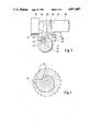
- FIG. 6 shows, in similar manner to FIG. 5, the apparatus of FIG. 1 as part of the scanner of our said co-pending application but in another projection configuration, and
- FIG. 7 shows an exploded, partially sectioned, side view of a sequencing device for a plurality of projection apparatuses each in accordance with this invention.
- the projection apparatus shown in FIG. 1 has a strobed laser light source 101 having a reflector 102 and a clear, non-distorting, heat dissipating glass 103 which is required to prevent heat from the source 101 distorting a transparency 104 mounted in an inverted T-shaped holder 105.
- An alternative arrangement for removing heat generated by light source 101 could be a cooling fan (not shown) blowing air upon the transparency 104.
- a projector lens assembly 106 projects a line pattern formed upon transparency 104 upon an object (not shown).
- the line pattern of radiation projected onto an object may be in linear form, for example vertical or horizontal, or a grid pattern formed by vertical and horizontal scanning, or in another alternative a pattern of radial lines. Whatever pattern is required for projection, it is firstly drawn to a large scale, photographed and then reduced in size to a predetermined dimension such as that commensurate with a standard 35 mm slide transparency.
- the inverted T-shaped holder 105 is pivotally located in a U-shaped base 107 having an inverted T-shaped cross-section.
- the mounting for the holder 105 is provided by a hardened pivot pin 108 mounted in wear-resistant bushings in opposed legs of the base 107.
- a spring loaded pin 109 extends through an arm of the base 107 to apply a turning force against an arm of the inverted T-shaped holder 105, the opposed arm of which is provided with a cam follower 110 located directly above the axis of a cam 111 mounted on a shaft 112.
- the cam follower 110 is, when in a true vertical position, thus arranged to be directly over the centre line of the shaft 112.
- the cam is arranged to have a series of rise portions each interspersed by a like number of dwell portions so that the radius of the cam increases in a series of steps before dropping to return to the minimum radius position.
- the shaft 112 is keyed to the cam 111 and the shaft is driven by a constant speed electric motor 113.
- the profile of the cam 111 is shown in an exagerated fashion for illustration purposes and in practice the radial difference between dwell heights would be, for example, 0.13 mm, depending on the movements of the projected pattern required.
- the shaft 112 is also arranged to carry a circular disk 114 having a hole (not shown) at a predetermined radius therein and a light sensor assembly 115 comprising a light emitting diode (LED) and a photodetector is positioned so that light from the LED is able to pass through the hole to be received by the photodetector.
- LED light emitting diode
- the disk 114 and light sensor assembly 115 act as a timing circuit so that when the hole in the disk 114 aligns with the light path between the LED and photodetector so a signal is produced to activate a controller 116 for the strobed light source 101 such that the light source fires at each dwell position of the cam 111 as is a camera (not shown) directed at the illuminated object profiles.
- the motor 113 is run up to the selected speed and the LED of the light sensor assembly 115 is switched on to ensure correct phase control for the strobe light source controller 116.
- the pattern transparency 104 has been moved arcuately to a new position as indicated by the double arrow-headed lines 117 and at each position the light source is fired, the object illuminated and the profiles recorded on the camera.
- a motor rotating at 60 r.p.m., a cam having twenty (20) dwell positions and a transparency defining 50 lines, in one second with only twenty camera shots there will be recorded 1,000 profiles defined by 1,000 slit apertures.
- the dwell on the cams or the number of slit apertures on the transparency will all increase the number of profiles illuminated.
- the apparatus will enable the provision of a slit aperture for processing every 0.00254 mm of an object surface in a linear (vertically or horizontally or in a grid) or radially patterned in dependence upon the pattern applied to the transparency.
- the cam profile is shown in an exaggerated fashion in FIG. 2 and the positions marked D denote dwell position where there is no movement of the cam follower and the R positions represent rises where the cam follower moves from one dwell position to another.
- TR represents the greatest movement capable of the cam follower which in the present exemplary embodiment is 15 mm over 12 dwell positions. Because of the expansion factor related to the distance of light projected, very small differences in dwell positions on the cam have a multiplied effect when projected. This is shown in FIG. 3 where the transparency 104 is shown vertically in solid lines and in a pivoted position 104' in broken lines, there being assumed to be only three slit apertures in this figure which are indicated as being applied to a planar object 150, the light beams being indicated by lines 118.
- FIG. 4 A further embodiment of the projection apparatus, principally intended for industrial use, is shown in FIG. 4 in which the strobe light source 101 is connected by a fibre optic cable 120 to a lens 121.
- the transparency 104 is mounted in a rectangular holder 130 which is reciprocally located between four low friction rollers 131 mounted in a guide base 132.
- the rollers 131 permit the holder 130 to be moved in a vertical direction only without play in other directions.
- a compression spring 133 having a pressure adjuster 134 biasses the holder 130 into contact with a cam follower 135 having a bearing surface 136 in contact with the profile of the cam 111.
- the light sensor 115 and controller 116 are not shown in the FIG. 4 for clarity.
- the cam follower bearing surface 112 is located directly above (in FIG. 4) the axis of the cam 111.
- rotation of the cam 111 moves the holder 130 and hence transparency 104 vertically in the direction of double arrow-headed line 140 and at each dwell position the strobed light source fires to illuminate the object (not shown) through however many slit apertures that are provided on the transparency. It will therefore be understood that at each rise position the slit pattern is progressively moved so that lines of light progressively move across the object.
- the apparatus shown in FIG. 1 is shown located in the scanning apparatus of our co-pending U.S. patent application No. 234,251 incorporated herein by reference.
- the projection apparatus of this invention replaces the prism 46 and stepping motor 47 shown in FIG. 8(b) of our said co-pending application.
- the projection apparatus of this invention is arranged to project light radiation onto a beam splitter 52 which transmit light into opposing paths (shown in FIG. 5 as upper and lower paths) onto an upper reflective 53 and a lower reflective 54.
- the upper and lower parts of an object are simultaneously illuminated each with a plurality of slits of light such that re-entrant portions of the object are illuminated.
- the apparatus is configured for horizontal movement so that patterns of light are projected from the left and right of an object.
- the cam dwells ensure that the pattern is stationary for a fraction of a micro second while the strobe fires and the camera records; this happens irrespective of the motor speed but, obviously the higher the speed, the less is the dwell time and no movement of the pattern is occuring.
- the devices are simple, small in size, and infinitely variable with cam changes, and/or transparency changes.
- the projection apparatus described above provides illumination of a plurality of profiles from one pattern transparency, with the dwells on the cam providing momentary non-movement of the transparency so that clear projection and positioning of the pattern upon an object is achieved.
- a sequencing device shown in FIG. 7 has a circularly crosssectioned housing 151 having a base plate 152.
- a lamp holder 153 for a D.C. lamp 154 is mounted on the base plate 152.
- the D.C. lamp may be halogen or some other convenient type having direct current to provide consistent output light levels, with an illumination of approximately five (5) million lux.
- the lamp holder is situated on the diametrical centre of the housing 151 and located in the peripheral wall of the housing at the height of the lamp and in a common plane are twelve equicircumferentially spaced mounting tubes 155 into each of which are secured fibre optic cables 156.
- Each group of fibre optic cables lead to the projection lens, for example 121, of a projection apparatus.
- a lid assembly 157 is shown in a raised position over the housing but in use the lid assembly would be positioned such that a lid 158 is located on top of the housing 151.
- a shaft 159 located in a roller bearing 160 and a thrust bearing 161.
- the shaft has a screw adjusting collar 162 to reduce play in the bearings and a further locking collar 163 is provided on top of the adjusting collar 162.
- the upper end of the shaft 159 is connected by a coupling 164 to a drive motor 165, the motor being supported by a bracket 166 and having a power supply cable 167.
- the lower end of the shaft 159 is connected to a stub 168, the stub supporting a reflector 169 having a radial rear portion 170 and including a condenser lens 171 in an opposed surface of the reflector to the radial area 170.
- the condenser lens and the radial portion of the reflector are arranged to be interposed between the lamp 154 and the fibre optic cables 156.
- An aperture 180 is provided in a wall of the reflector and positioned to be in alignment with the aperture 180 is a photodetector 181 located to be stationarily secured to the lid.
- the photodetector 181 has an output cable 182 for synchonising the rotation of the lens 171 with a charge coupled device sensing unit and can also be used in conjunction with the similar signals derived by the light sensor assembly 115 of the projection apparatus.
- the photodetector 181 acts as a synchonising device.
- the motor 165 rotates shaft 159 and hence the stub 168 to thereby rotate the condenser lense 171 about the lamp 154. Light is thus projected to each of the fibre optic cables 156 in turn so that each of the twelve projection apparatuses connected to a respective fibre optic cable illuminates an object.
- twelve projection apparatuses are positioned equi-circumferentially about an object. Starting from a datum position the projection apparatuses could be numbered 1 to 12.
- the fibre optic cables positioned circumferentially around the housing could be numbered from a datum 12, 6, 11, 5, 10, 4, 9, 3, 8, 2, 7, 1, or any other desirable order so that by such an arrangement opposing projection apparatuses will be illuminated in turn. It will therefore be understood that a very large number of patterns may be projected on to an object without the patterns overlapping with one another.
Abstract
Description
Claims (14)
Applications Claiming Priority (2)
| Application Number | Priority Date | Filing Date | Title |
|---|---|---|---|
| GB878724527A GB8724527D0 (en) | 1987-10-20 | 1987-10-20 | Projection apparatus |
| GB8724527 | 1987-10-20 |
Publications (1)
| Publication Number | Publication Date |
|---|---|
| US4917487A true US4917487A (en) | 1990-04-17 |
Family
ID=10625591
Family Applications (1)
| Application Number | Title | Priority Date | Filing Date |
|---|---|---|---|
| US07/234,275 Expired - Fee Related US4917487A (en) | 1987-10-20 | 1988-08-19 | Projection apparatus |
Country Status (4)
| Country | Link |
|---|---|
| US (1) | US4917487A (en) |
| EP (1) | EP0313193A3 (en) |
| JP (1) | JPH01161108A (en) |
| GB (1) | GB8724527D0 (en) |
Cited By (10)
| Publication number | Priority date | Publication date | Assignee | Title |
|---|---|---|---|---|
| US5208891A (en) * | 1991-10-07 | 1993-05-04 | The United State Of America As Represented By The Secretary Of The Navy | Fiber-optic viewgraph projector |
| US5253000A (en) * | 1991-08-01 | 1993-10-12 | Ursula Stoeckner | Device for projecting a moving image formed of light, shadow, and color |
| US5262844A (en) * | 1990-07-03 | 1993-11-16 | Bertin & Cie | Apparatus for determining the three-dimensional shape of an object optically without contact |
| US5426474A (en) * | 1994-03-22 | 1995-06-20 | Innersense, Inc. | Light projection system using randomized fiber optic bundle |
| US5636912A (en) * | 1994-09-15 | 1997-06-10 | Lg Electronics Inc. | Liquid crystal projector |
| US5971547A (en) * | 1997-07-22 | 1999-10-26 | Reilley; Peter | Astigmatic lenticular projector system |
| US6578969B1 (en) * | 1999-07-01 | 2003-06-17 | Carl Zeiss Jena Gmbh | Arrangement for cutting off radiation in projectors and/or illumination devices |
| CN102947739A (en) * | 2010-04-23 | 2013-02-27 | 德固萨有限责任公司 | Method and arrangement for coupling in radiation emitted by leds |
| US8755059B2 (en) | 2011-11-08 | 2014-06-17 | Taishita LLC | Portable multiuse projector with fiber optic projection |
| EP3819872A4 (en) * | 2018-08-21 | 2021-08-25 | Shining3D Tech Co., Ltd. | Image acquisition and processing methods and apparatuses for three-dimensional scanning, and three-dimensional scanning device |
Families Citing this family (1)
| Publication number | Priority date | Publication date | Assignee | Title |
|---|---|---|---|---|
| DE4213909A1 (en) * | 1992-04-28 | 1993-11-04 | Mtu Muenchen Gmbh | DEVICE FOR MEASURING EDGE PROFILES FROM EDGES |
Citations (31)
| Publication number | Priority date | Publication date | Assignee | Title |
|---|---|---|---|---|
| US891013A (en) * | 1907-01-25 | 1908-06-16 | John Hammond Smith | Method of reproducing objects. |
| US1382978A (en) * | 1919-10-18 | 1921-06-28 | Frank L Dyer | Photosculpture |
| US1514138A (en) * | 1923-01-22 | 1924-11-04 | Ars Ab | Projecting apparatus for the projection of panorama views upon stages |
| US1546636A (en) * | 1921-12-15 | 1925-07-21 | Engelmann William Fred | Process of plastically reproducing objects, especially human heads and faces |
| US1594607A (en) * | 1922-06-08 | 1926-08-03 | Engelmann William Fred | Apparatus for plastically reproducing objects |
| US2066996A (en) * | 1933-12-15 | 1937-01-05 | Morioka Isao | Process for manufacturing statues similar to objects |
| US2163124A (en) * | 1935-10-16 | 1939-06-20 | Photosculpture Ltd | Photosculpture |
| US2163125A (en) * | 1935-10-16 | 1939-06-20 | Photosculpture Ltd | Photosculpture |
| US2335127A (en) * | 1941-07-23 | 1943-11-23 | Ling Chung | Process and apparatus for photo sculpture |
| US3085923A (en) * | 1960-06-03 | 1963-04-16 | Kenneth L Agnew | Recording and reproducing the shape of three-dimensional objects |
| GB939261A (en) * | 1959-02-20 | 1963-10-09 | George Macdonald Reid | Improvements in or relating to methods of producing three-dimensional articles that are similar to three-dimensional originals |
| GB939262A (en) * | 1959-02-20 | 1963-10-09 | George Macdonald Reid | An apparatus for use in making an article from a cylindrical block of material |
| US3246570A (en) * | 1965-01-05 | 1966-04-19 | Chernolimpex Magyar Vegyiaru K | Automatic photomechanical equipment for preparing sculptures |
| US3546377A (en) * | 1968-06-12 | 1970-12-08 | Ovitron Corp | Video comparator using vidicons with delayed scanning |
| US3624371A (en) * | 1970-08-06 | 1971-11-30 | Cincinnati Milacron Inc | Apparatus for generating and recording a program and producing a finished part therefrom |
| US3688676A (en) * | 1969-06-20 | 1972-09-05 | John S Cruickshank | Photo recording assembly |
| US3690242A (en) * | 1969-06-20 | 1972-09-12 | John S Cruickshank | Photo recording assembly |
| US3796129A (en) * | 1970-09-25 | 1974-03-12 | J Cruickshank | Apparatus for the manufacture of three-dimensional reproduction of an object |
| US3866052A (en) * | 1973-11-02 | 1975-02-11 | Dynell Elec | Methods for generating signals defining three-dimensional object surfaces |
| US3884577A (en) * | 1973-01-08 | 1975-05-20 | Richard A Carpentier | Methods and apparatus for object reproduction |
| US3932923A (en) * | 1974-10-21 | 1976-01-20 | Dynell Electronics Corporation | Method of generating and constructing three-dimensional bodies |
| US3969577A (en) * | 1974-10-15 | 1976-07-13 | Westinghouse Electric Corporation | System for evaluating similar objects |
| US3976382A (en) * | 1972-11-14 | 1976-08-24 | A/S Kongsberg Vapenfabrik | Procedure and apparatus for determining the geometrical shape of a surface |
| US4060318A (en) * | 1976-03-22 | 1977-11-29 | Decca Limited | Projection apparatus |
| US4202612A (en) * | 1976-12-28 | 1980-05-13 | Solid Photography Inc. | Arrangement for sensing the geometric characteristics of an object |
| US4302097A (en) * | 1979-05-11 | 1981-11-24 | Gustav Chlestil | Three-dimensional representation of solid objects |
| US4458993A (en) * | 1981-10-05 | 1984-07-10 | Kempf Paul S | Fingerprint comparator |
| US4472056A (en) * | 1980-07-23 | 1984-09-18 | Hitachi, Ltd. | Shape detecting apparatus |
| US4491868A (en) * | 1981-05-06 | 1985-01-01 | Inspection Technology Inc. | Video image compensator for inspection apparatus |
| US4509075A (en) * | 1981-06-15 | 1985-04-02 | Oxbridge, Inc. | Automatic optical inspection apparatus |
| US4613234A (en) * | 1983-01-10 | 1986-09-23 | Lbp Partnership | Profile imaging techniques |
Family Cites Families (2)
| Publication number | Priority date | Publication date | Assignee | Title |
|---|---|---|---|---|
| JPS5452976A (en) * | 1977-10-04 | 1979-04-25 | Mitsubishi Electric Corp | Fluorescent screen exposure method for color braun tube |
| US4573073A (en) * | 1983-06-02 | 1986-02-25 | General Electric Company | Integrated lighting and camera system |
-
1987
- 1987-10-20 GB GB878724527A patent/GB8724527D0/en active Pending
-
1988
- 1988-08-17 EP EP19880307617 patent/EP0313193A3/en not_active Withdrawn
- 1988-08-19 US US07/234,275 patent/US4917487A/en not_active Expired - Fee Related
- 1988-08-24 JP JP63210388A patent/JPH01161108A/en active Pending
Patent Citations (31)
| Publication number | Priority date | Publication date | Assignee | Title |
|---|---|---|---|---|
| US891013A (en) * | 1907-01-25 | 1908-06-16 | John Hammond Smith | Method of reproducing objects. |
| US1382978A (en) * | 1919-10-18 | 1921-06-28 | Frank L Dyer | Photosculpture |
| US1546636A (en) * | 1921-12-15 | 1925-07-21 | Engelmann William Fred | Process of plastically reproducing objects, especially human heads and faces |
| US1594607A (en) * | 1922-06-08 | 1926-08-03 | Engelmann William Fred | Apparatus for plastically reproducing objects |
| US1514138A (en) * | 1923-01-22 | 1924-11-04 | Ars Ab | Projecting apparatus for the projection of panorama views upon stages |
| US2066996A (en) * | 1933-12-15 | 1937-01-05 | Morioka Isao | Process for manufacturing statues similar to objects |
| US2163124A (en) * | 1935-10-16 | 1939-06-20 | Photosculpture Ltd | Photosculpture |
| US2163125A (en) * | 1935-10-16 | 1939-06-20 | Photosculpture Ltd | Photosculpture |
| US2335127A (en) * | 1941-07-23 | 1943-11-23 | Ling Chung | Process and apparatus for photo sculpture |
| GB939261A (en) * | 1959-02-20 | 1963-10-09 | George Macdonald Reid | Improvements in or relating to methods of producing three-dimensional articles that are similar to three-dimensional originals |
| GB939262A (en) * | 1959-02-20 | 1963-10-09 | George Macdonald Reid | An apparatus for use in making an article from a cylindrical block of material |
| US3085923A (en) * | 1960-06-03 | 1963-04-16 | Kenneth L Agnew | Recording and reproducing the shape of three-dimensional objects |
| US3246570A (en) * | 1965-01-05 | 1966-04-19 | Chernolimpex Magyar Vegyiaru K | Automatic photomechanical equipment for preparing sculptures |
| US3546377A (en) * | 1968-06-12 | 1970-12-08 | Ovitron Corp | Video comparator using vidicons with delayed scanning |
| US3690242A (en) * | 1969-06-20 | 1972-09-12 | John S Cruickshank | Photo recording assembly |
| US3688676A (en) * | 1969-06-20 | 1972-09-05 | John S Cruickshank | Photo recording assembly |
| US3624371A (en) * | 1970-08-06 | 1971-11-30 | Cincinnati Milacron Inc | Apparatus for generating and recording a program and producing a finished part therefrom |
| US3796129A (en) * | 1970-09-25 | 1974-03-12 | J Cruickshank | Apparatus for the manufacture of three-dimensional reproduction of an object |
| US3976382A (en) * | 1972-11-14 | 1976-08-24 | A/S Kongsberg Vapenfabrik | Procedure and apparatus for determining the geometrical shape of a surface |
| US3884577A (en) * | 1973-01-08 | 1975-05-20 | Richard A Carpentier | Methods and apparatus for object reproduction |
| US3866052A (en) * | 1973-11-02 | 1975-02-11 | Dynell Elec | Methods for generating signals defining three-dimensional object surfaces |
| US3969577A (en) * | 1974-10-15 | 1976-07-13 | Westinghouse Electric Corporation | System for evaluating similar objects |
| US3932923A (en) * | 1974-10-21 | 1976-01-20 | Dynell Electronics Corporation | Method of generating and constructing three-dimensional bodies |
| US4060318A (en) * | 1976-03-22 | 1977-11-29 | Decca Limited | Projection apparatus |
| US4202612A (en) * | 1976-12-28 | 1980-05-13 | Solid Photography Inc. | Arrangement for sensing the geometric characteristics of an object |
| US4302097A (en) * | 1979-05-11 | 1981-11-24 | Gustav Chlestil | Three-dimensional representation of solid objects |
| US4472056A (en) * | 1980-07-23 | 1984-09-18 | Hitachi, Ltd. | Shape detecting apparatus |
| US4491868A (en) * | 1981-05-06 | 1985-01-01 | Inspection Technology Inc. | Video image compensator for inspection apparatus |
| US4509075A (en) * | 1981-06-15 | 1985-04-02 | Oxbridge, Inc. | Automatic optical inspection apparatus |
| US4458993A (en) * | 1981-10-05 | 1984-07-10 | Kempf Paul S | Fingerprint comparator |
| US4613234A (en) * | 1983-01-10 | 1986-09-23 | Lbp Partnership | Profile imaging techniques |
Cited By (14)
| Publication number | Priority date | Publication date | Assignee | Title |
|---|---|---|---|---|
| US5262844A (en) * | 1990-07-03 | 1993-11-16 | Bertin & Cie | Apparatus for determining the three-dimensional shape of an object optically without contact |
| US5253000A (en) * | 1991-08-01 | 1993-10-12 | Ursula Stoeckner | Device for projecting a moving image formed of light, shadow, and color |
| US5208891A (en) * | 1991-10-07 | 1993-05-04 | The United State Of America As Represented By The Secretary Of The Navy | Fiber-optic viewgraph projector |
| US5426474A (en) * | 1994-03-22 | 1995-06-20 | Innersense, Inc. | Light projection system using randomized fiber optic bundle |
| US5636912A (en) * | 1994-09-15 | 1997-06-10 | Lg Electronics Inc. | Liquid crystal projector |
| US5971547A (en) * | 1997-07-22 | 1999-10-26 | Reilley; Peter | Astigmatic lenticular projector system |
| US6578969B1 (en) * | 1999-07-01 | 2003-06-17 | Carl Zeiss Jena Gmbh | Arrangement for cutting off radiation in projectors and/or illumination devices |
| CN102947739A (en) * | 2010-04-23 | 2013-02-27 | 德固萨有限责任公司 | Method and arrangement for coupling in radiation emitted by leds |
| US20130114286A1 (en) * | 2010-04-23 | 2013-05-09 | Degudent Gmbh | Method and arrangement for coupling in radiation emitted by leds |
| CN102947739B (en) * | 2010-04-23 | 2014-11-19 | 德固萨有限责任公司 | Method and arrangement for coupling in radiation emitted by leds |
| US8979340B2 (en) * | 2010-04-23 | 2015-03-17 | Degudent Gmbh | Method and arrangement for coupling in radiation emitted by LEDs |
| US8755059B2 (en) | 2011-11-08 | 2014-06-17 | Taishita LLC | Portable multiuse projector with fiber optic projection |
| EP3819872A4 (en) * | 2018-08-21 | 2021-08-25 | Shining3D Tech Co., Ltd. | Image acquisition and processing methods and apparatuses for three-dimensional scanning, and three-dimensional scanning device |
| US11887321B2 (en) | 2018-08-21 | 2024-01-30 | Shining3D Tech Co., Ltd. | Three-dimensional scanning image acquisition and processing methods and apparatuses, and three-dimensional scanning device |
Also Published As
| Publication number | Publication date |
|---|---|
| GB8724527D0 (en) | 1987-11-25 |
| EP0313193A2 (en) | 1989-04-26 |
| EP0313193A3 (en) | 1990-09-26 |
| JPH01161108A (en) | 1989-06-23 |
Similar Documents
| Publication | Publication Date | Title |
|---|---|---|
| US4917487A (en) | Projection apparatus | |
| US3375362A (en) | Means to controllably direct a plurality of spotlights | |
| US6856440B2 (en) | Coplanar camera scanning system | |
| US4871256A (en) | Means for projecting patterns of light | |
| US6622053B1 (en) | Electronically controlled stage lighting system | |
| US4758093A (en) | Apparatus and method for 3-D measurement using holographic scanning | |
| CN113884284A (en) | Test method for simulating sunlight focusing burning | |
| EP0591386B1 (en) | Medical device for lighting a treatment field | |
| US4100404A (en) | Beam projector | |
| US3981574A (en) | Optical device | |
| US4895434A (en) | Apparatus and method for 3-D measurement using holographic scanning | |
| KR870005357A (en) | Detoxification device | |
| JPS60500071A (en) | projection device | |
| JPH09304682A (en) | Optical measuring device | |
| US5323301A (en) | Dimmable studio lighting device | |
| SU1352437A1 (en) | Lighting device | |
| EP2281264B1 (en) | System for automatically acquiring optically coded information, illuminator for said system and method for aligning with each other optical components of the system. | |
| CN211205711U (en) | Structured light module detection device | |
| JP2558948Y2 (en) | Lighting equipment for optical equipment | |
| SU1541489A1 (en) | Device for diagnosis of vehicle head lamps | |
| CN115685516A (en) | Monochromatic light hyperspectral system and control method | |
| SU1318822A1 (en) | Device for measuring parameters of optical systems | |
| SU537008A1 (en) | Device for oriented delivery of parts | |
| JPH09287927A (en) | Projecting-point moving type range finder | |
| US20070037303A1 (en) | Apparatus and method of illuminating the surface of a wafer in a wafer inspection system |
Legal Events
| Date | Code | Title | Description |
|---|---|---|---|
| AS | Assignment |
Owner name: L.B.P. PARTNERSHIP, 1706 WASHINGTON AVENUE, ST. LO Free format text: ASSIGNMENT OF ASSIGNORS INTEREST.;ASSIGNOR:CRUICKSHANK, JOHN S.;REEL/FRAME:004931/0436 Effective date: 19880802 Owner name: L.B.P. PARTNERSHIP, MISSOURI Free format text: ASSIGNMENT OF ASSIGNORS INTEREST;ASSIGNOR:CRUICKSHANK, JOHN S.;REEL/FRAME:004931/0436 Effective date: 19880802 |
|
| AS | Assignment |
Owner name: P&W/LBP MASTER PARTNERSHIP, MISSOURI Free format text: ASSIGNMENT OF ASSIGNORS INTEREST.;ASSIGNOR:LBP PARTNERSHIP, 1706 WASHINGTON AVE., ST. LOUIS, MO. 63103, A MO. GENERAL PARTNERSHIP;REEL/FRAME:005253/0226 Effective date: 19890501 |
|
| FEPP | Fee payment procedure |
Free format text: PAYOR NUMBER ASSIGNED (ORIGINAL EVENT CODE: ASPN); ENTITY STATUS OF PATENT OWNER: LARGE ENTITY |
|
| FPAY | Fee payment |
Year of fee payment: 4 |
|
| REMI | Maintenance fee reminder mailed | ||
| LAPS | Lapse for failure to pay maintenance fees | ||
| FP | Lapsed due to failure to pay maintenance fee |
Effective date: 19980422 |
|
| STCH | Information on status: patent discontinuation |
Free format text: PATENT EXPIRED DUE TO NONPAYMENT OF MAINTENANCE FEES UNDER 37 CFR 1.362 |