US4918907A - Forming and filling flexible plastic packaging - Google Patents
Forming and filling flexible plastic packaging Download PDFInfo
- Publication number
- US4918907A US4918907A US07/146,038 US14603888A US4918907A US 4918907 A US4918907 A US 4918907A US 14603888 A US14603888 A US 14603888A US 4918907 A US4918907 A US 4918907A
- Authority
- US
- United States
- Prior art keywords
- articles
- receptacles
- web
- group
- filling station
- Prior art date
- Legal status (The legal status is an assumption and is not a legal conclusion. Google has not performed a legal analysis and makes no representation as to the accuracy of the status listed.)
- Expired - Fee Related
Links
Images

Classifications
-
- B—PERFORMING OPERATIONS; TRANSPORTING
- B65—CONVEYING; PACKING; STORING; HANDLING THIN OR FILAMENTARY MATERIAL
- B65B—MACHINES, APPARATUS OR DEVICES FOR, OR METHODS OF, PACKAGING ARTICLES OR MATERIALS; UNPACKING
- B65B9/00—Enclosing successive articles, or quantities of material, e.g. liquids or semiliquids, in flat, folded, or tubular webs of flexible sheet material; Subdividing filled flexible tubes to form packages
- B65B9/02—Enclosing successive articles, or quantities of material between opposed webs
- B65B9/04—Enclosing successive articles, or quantities of material between opposed webs one or both webs being formed with pockets for the reception of the articles, or of the quantities of material
-
- B—PERFORMING OPERATIONS; TRANSPORTING
- B65—CONVEYING; PACKING; STORING; HANDLING THIN OR FILAMENTARY MATERIAL
- B65B—MACHINES, APPARATUS OR DEVICES FOR, OR METHODS OF, PACKAGING ARTICLES OR MATERIALS; UNPACKING
- B65B47/00—Apparatus or devices for forming pockets or receptacles in or from sheets, blanks, or webs, comprising essentially a die into which the material is pressed or a folding die through which the material is moved
- B65B47/08—Apparatus or devices for forming pockets or receptacles in or from sheets, blanks, or webs, comprising essentially a die into which the material is pressed or a folding die through which the material is moved by application of fluid pressure
Definitions
- the invention relates to forming and filling flexible plastic packaging.
- a web of plastic is advanced through a vacuum thermoformer (where the plastic web is formed to provide receptacles for receiving articles), a filling station (where articles are placed in the formed receptacles), a sealer (where a second sheet is placed over the filled receptacles and sealed to portions of the web around the receptacles to provide covers), and a cutter (where the plastic web is cut at portions between receptacles into separate packages).
- thermoforming in which a vacuum in a female mold draws heated film into the desired shape against the female mold, with or without assistance from positive pressure on the other side of the plastic
- positive male forming in which a vacuum in a male mold and positive pressure applied on the other side of the plastic draw the heated film into the desired shape against the male mold
- male plug-assisted negative forming in which a vacuum in a female mold and a mechanical male plug on the opposite side of film are used, with or without an optional sandwich heater.
- Such apparatus has been used to form both rigid and flexible receptacles, the former in general having walls that are 8 to 50 mils in thickness (depending on the plastic and application) and maintain their shape, the latter in general having walls that are less than 8 mils in thickness and readily flex and change shape.
- the differences in size and properties of rigid vis-a-vis flexible walls result in differences in the responses of the plastics to heat and force and in the types of thermoforming procedures employed.
- Flexible film thermoforming conventionally involves simple application of vacuum to easily draw the heated plastic to the mold; there often is, however, substantial stretching of the plastic, resulting in uneven reduction in wall thickness.
- Rigid wall thermoforming may very well involve procedures employing assistance from positive pressure in addition to vacuum and has also involved a two-step procedure of first providing a light vacuum to provide initial contour and thereafter providing both vacuum and pressure to force the film into the shape of the mold.
- the invention features automatically supplying products assembled at an assembler to a filling station of a form and fill packaging line by using a transporting line that receives the products one-after another as assembled and presents them in groups at the filling station.
- a transfer mechanism then transfers the articles one group at a time to corresponding receptacles formed in a web of plastic at the filling station.
- the transporting line includes a gate for selectively removing articles from it and directing them to a hopper for temporary storage and a reentry mechanism for causing the articles in the hopper to reenter the transporting line.
- the transporting line includes a track on which the articles are maintained in a predetermined orientation as they move along the track.
- the conveyor belt at the end of the track for presenting the articles at the filling station.
- the conveyor belt carries the articles in two rows to the filling station, and there are two tracks for carrying the articles to the conveyor belt.
- the articles are syringes that have wings that are supported by spaced parallel horizontal track portions and have vertically oriented bodies between the track portions during transport.
- the invention features inspecting articles prior to transfer in groups to receptacles in order to identify defective products and selectively remove products so that only groups containing defect free products are transferred.
- defective articles removed from the conveyor are transferred to one bin and defect-free articles are transferred to another.
- the transfer mechanism waits while the conveyor incrementally moves articles to the location for transfer to the packaging line until there is a complete group of defect-free articles.
- the invention features transferring a group of products on a conveyor to a receiving station, using separately movable product engagers to change the relative positions of the products in the groups with respect to each other (by moving the relative positions of the product engagers) prior to dropping the products off at the receiving station.
- the product engagers are vacuum engagement members provided on the ends of longitudinally extendable cross-arms.
- the ends of the cross-arms are pneumatically actuated to an extended stop position and spring-returned to a retracted position.
- the cross-arms are supported on a robot that is capable of movement along three orthogonal axes.
- the invention features providing more uniform plastic wall thickness in flexible receptacles formed in a plastic web in a vacuum thermoformer by initially providing a first pressure difference on opposite sides of the heated plastic web positioned in the mold to provide an initial contour with substantially uniform stretching, and thereafter applying a second, larger pressure difference to form the plastic into its desired shape.
- the more uniform thickness permits use of a thinner web of plastic material for a given desired wall thickness in the flexible product, and the two step procedure greatly reduces stretching and associated weakened material.
- both a male mold and a female mold are used, and a light vacuum is applied in the female mold to provide the first pressure difference. Vacuum is applied in the male mold, and air pressure is applied in the female mold to provide the second pressure difference.
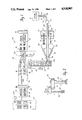
- FIG. 1 is a diagrammatic plan view of form and fill packaging apparatus and associated transporting line according to, the invention.
- FIG. 2 is a diagrammatic elevation of a robot used in the FIG. 1 apparatus to transfer syringes from a supply belt to formed receptacles.
- FIG. 3 is a diagrammatic perspective view of an article pickup mechanism of the FIG. 1 apparatus.
- FIG. 4 is a diagrammatic bottom plan view of the FIG. 3 pickup mechanism.
- FIG. 5 is a diagrammatic vertical sectional view of an engagement foot of the FIG. 3 mechanism shown engaging a syringe.
- FIG. 6 is a diagrammatic vertical sectional view of a heater and portions of multiple-receptacle molds of a thermoformer of the FIG. 1 apparatus in position during an initial step of a forming operation.
- FIG. 7 is a diagrammatic vertical sectional view of a heater and portions of multiple receptacle molds of the FIG. 1 apparatus in a later step of the forming operation.
- FIG. 1 there is shown form and fill packaging apparatus 10 used in conjunction with syringe assembler 11 and transporting line 13, for transporting assembled syringes 18 for packaging at apparatus 10.
- Form and fill apparatus 10 includes vacuum thermoformer 12, for forming web of plastic 14 advanced from supply roll 15 through it so as to provide formed receptacles 16 for receiving syringes 18 at downstream filling station 19.
- Seal and cover unit 20 is positioned to provide a cover over filled receptacles 16, and cutter 22 is positioned to cut the formed, filled, and sealed web into individual packaged products 24 containing five syringes 18 each.
- Transporting line 13 includes in line tracks 25, 27 on which syringes 18 are transported with their wings extending outward over spaced horizontal portions of tracks 25, 27, the syringe bodies being vertically oriented in the space between the two portions of the tracks. Orienting rolls 61 capture syringes 18 in horizontal orientation and introduce them vertically into track 25. Diverter 23 splits the syringes coming from syringe assembler 11 on track 25 into two streams, one along the continuation of track 25 and one along track 27. Downstream of diverter 23 on tracks 25, 27 are chute gates 29 for selectively discharging syringes into hoppers 31.
- Each hopper 31 has an associated elevator 51, rotary disk bowl feeder 35, and orientation rolls 37 (to place syringes in vertical orientation) for returning syringes in hoppers 31 to their respective tracks 25, 27, as desired.
- Syringes are moved along tracks 25, 27 by upstream star wheel conveyors 39 and downstream star wheel conveyors 41.
- Track 25 has a one-half C end section to discharge chute 43 to reorient syringes 18 to a horizontal position and deliver syringes 18 horizontally to the left hand belt of infeed conveyor belt 26.
- Track 27 similarly has a one-half C end-section and associated chute 145 for delivering syringes in a horizontal manner to the right hand belt of infeed conveyor belt 26.
- Each belt of conveyor belt 26 has troughs 28 that are appropriately spaced for pick up by robot 30 (an Adept robot) and discharge into receptacles 16.
- Visual inspection monitor 45 is along belt 26.
- At the end of belt 26 is two compartment bin 49 having one compartment for good syringes and one for defective syringes and a mechanism (not shown) for selectively directing good and defective syringes to their respective compartments.
- Robot 30 and multiple pickup member 32 of loading station 19 are positioned near the junction of infeed belt 26 and the web of formed receptacles 16, to load syringes 18 from belt 26 into receptacles 16.
- Conveyor 47 and robot 245 are adjacent to the end of belt 29, carrying packaged products 24 from cutter 22.
- robot 30 includes rotatable main shaft 33, primary arm 34 connected to it, secondary arm 36 rotatably connected to arm 34, and shaft 38.
- Shaft 38 is mounted for vertical movement on arm 36 and carries, on its lower end, bracket 40, for mounting to pickup member 32.
- pickup member 32 includes flange 34, for attaching to bracket 40, and cross arms 36 secured at respective ends to four pads 88, each of which has ten rubber feet 41 in position to engage syringes 18.
- each foot 41 has a U-shaped recess 42 and vacuum passage 44, leading to recess 42 and connected to vacuum tubes 46.
- Robot 245 carries a multiple pickup member and rotatable arms (not shown) that is similar to member 32, except that its feet are shaped like suction cups, and its cross arms are longitudinally extendable.
- Molds 50, 52 include passages 54 for selectively providing vacuum or positive pressure to region 56 between them.
- web 14 is advanced from roll 15, heated at heater 48 (FIGS. 6 and to, e.g., about 80° C. to 90° C., and thereafter advanced to position between male and female molds 50, 52. Heated web 14 is subjected to a light vacuum applied at female mold 52, causing a difference in pressure on opposite sides of web 14 that urges web 14 to begin assuming the shape of female mold 52 with uniform stretching (FIG. 6). Thereafter vacuum is applied at male mold 50 and positive pressure is applied at female mold 52 (FIG. 7), causing a larger difference in pressure (and in the opposite direction) and web 14 to move into contact with water-cooled (e.g., about 65° F.) male mold 50 continuously along its surface.
- water-cooled e.g., about 65° F.
- the two-step procedure has about a 3-5 second cycle, with about 1/4 to 1/2 second in the first step, depending on the plastic and thickness.
- the two-step procedure greatly reduces stretching and the resulting weakened material and provides more uniform wall thickness in the resulting formed receptacle. Thinner, less expensive stock can thus be used while maintaining desired, minimum thicknesses.
- use of 4.5 mil K resin (butadiene-styrene polymer) plastic web results in a minimum wall thickness of 1.5 mils in receptacles 16, which is significantly better than the 0.75 mil minimum thickness resulting from 6.5 mil thick starting material when using a prior process.
- web 14 is advanced to move a fresh portion of the web into thermoformer 12 and to move twenty formed receptacles 16 into position at filling station 19 for simultaneous filling with a group of twenty syringes 18.
- Syringes 18 are assembled at syringe assembler 11 and discharged to orienting rolls 61 one-at-a-time in horizontal orientation as they are assembled. Syringes 18 are vertically oriented at rolls 61 and received on track 25, where the syringes maintain the vertical orientation with the wings extending over spaced horizontal members of track 25. Star wheel mechanism 39 pushes syringes between its two wheels along track 25. At diverter 23 some of the syringes are diverted to track 27. The syringes continue along tracks 25, 27 and are delivered at chutes 43, 145 in horizontal orientation to the left- and right-hand rows of troughs 28, receiving an additional push at star wheels 41, 43.
- syringes 18 can be discharged and temporarily stored into hopper 31 and later incorporated back into the feed to infeed belt 26 at a time when form and fill line 10 is operating faster than assembler 11 or at a time when assembler 11 is not operating.
- the discharge of syringes into hopper 31 is controlled by chute gates 29.
- the syringes reenter tracks 25, 27, they are raised by elevator 30 to rotary disk bowl feeder 35, which feeds the syringes 18 to orienting rolls 37 at which the syringes are placed in their vertical orientation with the wings on opposite sides of an opening between horizontal track members.
- Hoppers 31 can also be manually loaded with previously assembled syringes in the event of failure of syringe assembler 11.
- Syringes delivered to troughs 28 of infeed belt 26 are advanced toward form and fill line apparatus 10 and are scanned by inspection station 45 to determine if there are any defective syringes (for example, whether the spacing between the wings and the plunger is within specifications, and whether all parts are present).
- the left- and right-hand belts of conveyor belt 26 operate synchronously when defective parts are not detected. Twenty syringes 18 are transferred at a time by robot 30 in four groups of five.
- inspection station 45 If inspection station 45 identifies a faulty syringe, it is dropped into bin 47 along with any other syringes that would prevent transfer of a group of twenty defect free syringes; for example, if the defective syringe was the fourth one from the front on the right-hand side of a group of twenty to be transferred, then the right-hand belt advances four increments, discharging the defective fourth syringe and the three syringes before it on the right-hand belt into the bin.
- the gate in bin 47 directs the first three defect free syringes to one compartment and the defective fourth syringe to another.
- pickup member 32 In making the transfer of syringes 18 from belt 26 to receptacles 16, pickup member 32 is lowered into position over infeed belt 26 by vertical movement of shaft 38, and a vacuum applied to feet 41 causes engagement of syringes 18, two feet 41 engaging each syringe 18. Pickup member 32 is then raised by movement of shaft 38 and moved into the position shown in FIG. 1 by relative rotation of arms 34, 36 and rotation of primary shaft 33. Pickup member 32 is then lowered, and the vacuums are disengaged, permitting syringes 18 to fall into their respective receptacles 16. In travel of syringes 18 from assembler 11 to receptacles 16, syringes 18 maintain predetermined orientations during travel and are captured at all times.
- the filled receptacles 16 are moved to seal and cover unit 20, where a cover sheet is sealed to the portions of web 14 between and around the receptacles.
- the loaded, covered, and sealed receptacles are then vertically and horizontally cut at cutter 22 to provide individual packaged products 24 of five syringes each.
- Robot 245 (similar to robot 30) transfers sealed packaged products 24, four at a time, to four boxes 58 on conveyor 47, alternating the orientation of each layer, and extending arms 36 before releasing packaged products 24 in boxes 58 to provide spacing for boxes 58. After a set of boxes 58 has been loaded, conveyor 47 moves a new set of four boxes 58 into position.
- Packaged products 24 can be sterilized by electron beam, ethylene oxide, or radiation sterilization and reliably maintain their integrity and sterilization, owing to the wall thickness.
Abstract
Description
Claims (41)
Priority Applications (5)
| Application Number | Priority Date | Filing Date | Title |
|---|---|---|---|
| US07/146,038 US4918907A (en) | 1988-01-20 | 1988-01-20 | Forming and filling flexible plastic packaging |
| JP1011736A JPH024606A (en) | 1988-01-20 | 1989-01-20 | Automatic assembly packer for article and method |
| EP89300575A EP0329284B1 (en) | 1988-01-20 | 1989-01-20 | Forming and filling flexible plastic packaging, packaging, and assembling and packaging, articles, and transferring groups of products |
| DE8989300575T DE68903005T2 (en) | 1988-01-20 | 1989-01-20 | MANUFACTURE AND FILLING OF FLEXIBLE PLASTIC PACKAGING, PACKAGING, ASSEMBLY AND PACKAGING OF ARTICLES AND TRANSFER OF PRODUCT GROUPS. |
| EP19910116173 EP0464876A3 (en) | 1988-01-20 | 1989-01-20 | Forming and filling flexible plastic packaging, packaging, and assembling and packaging, articles, and transferring groups of products |
Applications Claiming Priority (1)
| Application Number | Priority Date | Filing Date | Title |
|---|---|---|---|
| US07/146,038 US4918907A (en) | 1988-01-20 | 1988-01-20 | Forming and filling flexible plastic packaging |
Publications (1)
| Publication Number | Publication Date |
|---|---|
| US4918907A true US4918907A (en) | 1990-04-24 |
Family
ID=22515620
Family Applications (1)
| Application Number | Title | Priority Date | Filing Date |
|---|---|---|---|
| US07/146,038 Expired - Fee Related US4918907A (en) | 1988-01-20 | 1988-01-20 | Forming and filling flexible plastic packaging |
Country Status (4)
| Country | Link |
|---|---|
| US (1) | US4918907A (en) |
| EP (2) | EP0464876A3 (en) |
| JP (1) | JPH024606A (en) |
| DE (1) | DE68903005T2 (en) |
Cited By (21)
| Publication number | Priority date | Publication date | Assignee | Title |
|---|---|---|---|---|
| US5060455A (en) * | 1990-06-28 | 1991-10-29 | Ameco Corporation | Robotic case packing system and method |
| US5187921A (en) * | 1990-09-04 | 1993-02-23 | Glaxo Group Limited | Method and apparatus for filling cavities |
| WO1993018969A1 (en) * | 1992-03-26 | 1993-09-30 | Prototype Equipment Corporation | Potato chip package vertical packaging machine |
| US5623810A (en) * | 1996-03-29 | 1997-04-29 | Ethicon, Inc. | Method for making sterile suture packages |
| US5687541A (en) * | 1994-06-10 | 1997-11-18 | Johnson & Johnson Vision Products, Inc. | Automated apparatus and method for preparing contact lenses for inspection and packaging |
| US5819502A (en) * | 1996-05-09 | 1998-10-13 | Kyowa Machinery Co., Ltd. | Shifting apparatus for objects such as eggs |
| US5848514A (en) * | 1995-05-01 | 1998-12-15 | Johnson & Johnson Vision Products, Inc. | Packaging arrangement |
| US5987855A (en) * | 1997-07-03 | 1999-11-23 | Ethicon, Inc. | Method of and apparatus for sealing surgical suture packages |
| US20030017066A1 (en) * | 2001-07-19 | 2003-01-23 | Baxter International Inc. | Apparatus, flexible bag and method for dispensing |
| US20030051443A1 (en) * | 2001-09-19 | 2003-03-20 | Takeshi Kodai | Thermoforming method for film on blister packing machines and apparatus for it |
| US20040144800A1 (en) * | 2003-01-24 | 2004-07-29 | Baxter International, Inc. | Liquid dispenser and flexible bag therefor |
| US20040144799A1 (en) * | 2003-01-24 | 2004-07-29 | Baxter International Inc. | Liquid dispenser and flexible bag therefor |
| US6769231B2 (en) | 2001-07-19 | 2004-08-03 | Baxter International, Inc. | Apparatus, method and flexible bag for use in manufacturing |
| US20050011908A1 (en) * | 2003-07-16 | 2005-01-20 | Baxter International, Inc. | Dispenser and pressure/vacuum converting machine |
| US6905314B2 (en) | 2001-10-16 | 2005-06-14 | Baxter International Inc. | Pump having flexible liner and compounding apparatus having such a pump |
| US20060132247A1 (en) * | 2004-12-20 | 2006-06-22 | Renesas Technology Corp. | Oscillator and charge pump circuit using the same |
| US20080056862A1 (en) * | 2006-09-02 | 2008-03-06 | Uhlmann Pac-Systeme Gmbh & Co. Kg | Apparatus for loading small objects into blisters of packaging foil |
| US20080184671A1 (en) * | 2005-06-10 | 2008-08-07 | Tim Fleckenstein | Container Filling and Locking Device |
| US20080282646A1 (en) * | 2004-02-09 | 2008-11-20 | Detlev Gertitschke | Method and Device For Transferring Products From a Supply Vessel Into the Blisters of a Foil |
| CN102765591A (en) * | 2012-08-07 | 2012-11-07 | 江西科伦医疗器械制造有限公司 | Automatic material placing system of disposable sterile syringe |
| US11446205B2 (en) * | 2018-07-26 | 2022-09-20 | Uhlmann Pac-Systeme Gmbh & Co. Kg | Blister pack for medicinal products and tool for producing the blister pack |
Families Citing this family (4)
| Publication number | Priority date | Publication date | Assignee | Title |
|---|---|---|---|---|
| US4918907A (en) | 1988-01-20 | 1990-04-24 | T W Kutter Inc. | Forming and filling flexible plastic packaging |
| DE19860577A1 (en) * | 1998-12-29 | 2000-07-06 | Zeh Karl | Process for packaging a preformed piece |
| US9434651B2 (en) | 2012-05-26 | 2016-09-06 | James R. Glidewell Dental Ceramics, Inc. | Method of fabricating high light transmission zirconia blanks for milling into natural appearance dental appliances |
| US11731312B2 (en) | 2020-01-29 | 2023-08-22 | James R. Glidewell Dental Ceramics, Inc. | Casting apparatus, cast zirconia ceramic bodies and methods for making the same |
Citations (9)
| Publication number | Priority date | Publication date | Assignee | Title |
|---|---|---|---|---|
| US3517478A (en) * | 1967-11-17 | 1970-06-30 | Federal Cartridge Corp | Cartridge packaging machine |
| US3623596A (en) * | 1970-02-05 | 1971-11-30 | Garvey Products Corp | Accumulating table |
| US3729888A (en) * | 1970-06-20 | 1973-05-01 | Machine for transferring molded chocolate products from their shaping molds to packing boxes | |
| US3874143A (en) * | 1972-07-12 | 1975-04-01 | Lehigh Press | Packaging method and apparatus |
| US3942934A (en) * | 1973-10-19 | 1976-03-09 | Takeda Chemical Industries, Ltd. | Mold assembly for use in packaging machine |
| US4506495A (en) * | 1981-01-23 | 1985-03-26 | Ima-Industria Macchine Automatiche S.P.A. | Machine for producing blister packages |
| US4514956A (en) * | 1982-03-05 | 1985-05-07 | E. I. Du Pont De Nemours And Company | Vacuum transfer apparatus for packing layers of articles in a container |
| US4569183A (en) * | 1983-02-09 | 1986-02-11 | Ptx-Pentronix, Inc. | Tray locator and loader for conveyor apparatus, and method |
| US4655026A (en) * | 1985-12-11 | 1987-04-07 | Wigoda Luis T | Pill dispensing machine |
Family Cites Families (2)
| Publication number | Priority date | Publication date | Assignee | Title |
|---|---|---|---|---|
| US3441983A (en) * | 1963-09-09 | 1969-05-06 | Dow Chemical Co | Apparatus for formation of thermoplastic sheet into a cup-like container |
| US4918907A (en) | 1988-01-20 | 1990-04-24 | T W Kutter Inc. | Forming and filling flexible plastic packaging |
-
1988
- 1988-01-20 US US07/146,038 patent/US4918907A/en not_active Expired - Fee Related
-
1989
- 1989-01-20 JP JP1011736A patent/JPH024606A/en active Pending
- 1989-01-20 DE DE8989300575T patent/DE68903005T2/en not_active Expired - Fee Related
- 1989-01-20 EP EP19910116173 patent/EP0464876A3/en not_active Withdrawn
- 1989-01-20 EP EP89300575A patent/EP0329284B1/en not_active Expired - Lifetime
Patent Citations (9)
| Publication number | Priority date | Publication date | Assignee | Title |
|---|---|---|---|---|
| US3517478A (en) * | 1967-11-17 | 1970-06-30 | Federal Cartridge Corp | Cartridge packaging machine |
| US3623596A (en) * | 1970-02-05 | 1971-11-30 | Garvey Products Corp | Accumulating table |
| US3729888A (en) * | 1970-06-20 | 1973-05-01 | Machine for transferring molded chocolate products from their shaping molds to packing boxes | |
| US3874143A (en) * | 1972-07-12 | 1975-04-01 | Lehigh Press | Packaging method and apparatus |
| US3942934A (en) * | 1973-10-19 | 1976-03-09 | Takeda Chemical Industries, Ltd. | Mold assembly for use in packaging machine |
| US4506495A (en) * | 1981-01-23 | 1985-03-26 | Ima-Industria Macchine Automatiche S.P.A. | Machine for producing blister packages |
| US4514956A (en) * | 1982-03-05 | 1985-05-07 | E. I. Du Pont De Nemours And Company | Vacuum transfer apparatus for packing layers of articles in a container |
| US4569183A (en) * | 1983-02-09 | 1986-02-11 | Ptx-Pentronix, Inc. | Tray locator and loader for conveyor apparatus, and method |
| US4655026A (en) * | 1985-12-11 | 1987-04-07 | Wigoda Luis T | Pill dispensing machine |
Non-Patent Citations (2)
| Title |
|---|
| Tiromed Advanced Form/Fill/Seal Technology, Meeting Today s Critical Challenges. * |
| Tiromed Advanced Form/Fill/Seal Technology, Meeting Today's Critical Challenges. |
Cited By (33)
| Publication number | Priority date | Publication date | Assignee | Title |
|---|---|---|---|---|
| US5060455A (en) * | 1990-06-28 | 1991-10-29 | Ameco Corporation | Robotic case packing system and method |
| US5187921A (en) * | 1990-09-04 | 1993-02-23 | Glaxo Group Limited | Method and apparatus for filling cavities |
| WO1993018969A1 (en) * | 1992-03-26 | 1993-09-30 | Prototype Equipment Corporation | Potato chip package vertical packaging machine |
| US5251422A (en) * | 1992-03-26 | 1993-10-12 | Prototype Equipment Corporation | Potato chip package vertical packaging machine |
| US5279099A (en) * | 1992-03-26 | 1994-01-18 | Prototype Equipment Corporation | Machine for testing pneumatically sealed bag |
| US5284003A (en) * | 1992-03-26 | 1994-02-08 | Prototype Equipment Corporation | Machine for conditioning product in a sealed bag |
| USRE37432E1 (en) * | 1994-06-10 | 2001-11-06 | Johnson & Johnson Vision Products, Inc. | Automated apparatus and method for preparing contact lenses for inspection and packaging |
| US5687541A (en) * | 1994-06-10 | 1997-11-18 | Johnson & Johnson Vision Products, Inc. | Automated apparatus and method for preparing contact lenses for inspection and packaging |
| US5848514A (en) * | 1995-05-01 | 1998-12-15 | Johnson & Johnson Vision Products, Inc. | Packaging arrangement |
| US5623810A (en) * | 1996-03-29 | 1997-04-29 | Ethicon, Inc. | Method for making sterile suture packages |
| US5819502A (en) * | 1996-05-09 | 1998-10-13 | Kyowa Machinery Co., Ltd. | Shifting apparatus for objects such as eggs |
| US5987855A (en) * | 1997-07-03 | 1999-11-23 | Ethicon, Inc. | Method of and apparatus for sealing surgical suture packages |
| US20040094573A1 (en) * | 2001-07-19 | 2004-05-20 | Baxter International Inc. | Flow control apparatus for use in dispensing fluent material |
| US20030017066A1 (en) * | 2001-07-19 | 2003-01-23 | Baxter International Inc. | Apparatus, flexible bag and method for dispensing |
| US6769231B2 (en) | 2001-07-19 | 2004-08-03 | Baxter International, Inc. | Apparatus, method and flexible bag for use in manufacturing |
| US6748721B2 (en) * | 2001-09-19 | 2004-06-15 | Mutual Corporation | Thermoforming method for film on blister packing machines and apparatus for it |
| US20030051443A1 (en) * | 2001-09-19 | 2003-03-20 | Takeshi Kodai | Thermoforming method for film on blister packing machines and apparatus for it |
| KR20030025171A (en) * | 2001-09-19 | 2003-03-28 | 가부시키가이샤 뮤추얼 | Thermoforming method for film on blister packing machines and apparatus for it |
| US6905314B2 (en) | 2001-10-16 | 2005-06-14 | Baxter International Inc. | Pump having flexible liner and compounding apparatus having such a pump |
| US7237691B2 (en) | 2003-01-24 | 2007-07-03 | Baxter International Inc. | Flexible bag for fluent material dispenser |
| US20040144800A1 (en) * | 2003-01-24 | 2004-07-29 | Baxter International, Inc. | Liquid dispenser and flexible bag therefor |
| US20040144799A1 (en) * | 2003-01-24 | 2004-07-29 | Baxter International Inc. | Liquid dispenser and flexible bag therefor |
| US7007824B2 (en) | 2003-01-24 | 2006-03-07 | Baxter International Inc. | Liquid dispenser and flexible bag therefor |
| US20050011908A1 (en) * | 2003-07-16 | 2005-01-20 | Baxter International, Inc. | Dispenser and pressure/vacuum converting machine |
| US20080282646A1 (en) * | 2004-02-09 | 2008-11-20 | Detlev Gertitschke | Method and Device For Transferring Products From a Supply Vessel Into the Blisters of a Foil |
| US20060132247A1 (en) * | 2004-12-20 | 2006-06-22 | Renesas Technology Corp. | Oscillator and charge pump circuit using the same |
| US20080184671A1 (en) * | 2005-06-10 | 2008-08-07 | Tim Fleckenstein | Container Filling and Locking Device |
| US7937907B2 (en) * | 2005-06-10 | 2011-05-10 | Robert Bosch Gmbh | Container filling and locking device |
| US20080056862A1 (en) * | 2006-09-02 | 2008-03-06 | Uhlmann Pac-Systeme Gmbh & Co. Kg | Apparatus for loading small objects into blisters of packaging foil |
| US7430841B2 (en) * | 2006-09-02 | 2008-10-07 | Uhlmann Pac-Systeme Gmbh & Co. Kg | Apparatus for loading small objects into blisters of packaging foil |
| CN102765591A (en) * | 2012-08-07 | 2012-11-07 | 江西科伦医疗器械制造有限公司 | Automatic material placing system of disposable sterile syringe |
| CN102765591B (en) * | 2012-08-07 | 2014-04-16 | 江西科伦医疗器械制造有限公司 | Automatic material placing system of disposable sterile syringe |
| US11446205B2 (en) * | 2018-07-26 | 2022-09-20 | Uhlmann Pac-Systeme Gmbh & Co. Kg | Blister pack for medicinal products and tool for producing the blister pack |
Also Published As
| Publication number | Publication date |
|---|---|
| DE68903005D1 (en) | 1992-11-05 |
| EP0329284A3 (en) | 1989-11-15 |
| DE68903005T2 (en) | 1993-02-25 |
| EP0329284A2 (en) | 1989-08-23 |
| JPH024606A (en) | 1990-01-09 |
| EP0329284B1 (en) | 1992-09-30 |
| EP0464876A3 (en) | 1992-05-13 |
| EP0464876A2 (en) | 1992-01-08 |
Similar Documents
| Publication | Publication Date | Title |
|---|---|---|
| US4918907A (en) | Forming and filling flexible plastic packaging | |
| JP4256676B2 (en) | Apparatus and method for product packaging | |
| JP3955327B2 (en) | Device for loading articles, especially filled flat bags into cardboard boxes | |
| US10737810B2 (en) | Device and method for filling nested containers | |
| JPH11503095A (en) | Multi-pack packaging equipment | |
| US4709535A (en) | Packaging loader apparatus for sliced food products | |
| US3906705A (en) | Apparatus for filling cartons | |
| US20220073402A1 (en) | Glass manufacturing apparatus and method | |
| US5803702A (en) | Vision inspection system for double stacked packs | |
| US6582215B2 (en) | Automatic slug feeder for golf ball core forming apparatus | |
| US20020148203A1 (en) | Method and apparatus for packaging flexible containers | |
| US5862649A (en) | Method and device for packaging cans or tubes | |
| JP4200283B2 (en) | Article transfer device for bread bagging machine | |
| EP0941929B1 (en) | Vision inspection system for double stacked packs | |
| US20230348125A1 (en) | Packing machine for horizontal and vertical packing of articles into a packing box | |
| FI104482B (en) | Device for feeding packing container preparations | |
| JP3708166B2 (en) | Fruit and vegetable boxing equipment | |
| US20210354933A1 (en) | Method and assembly for transferring products | |
| US20230382585A1 (en) | Method and packaging machine for producing and checking lister packs | |
| JP2015151162A (en) | Conveyance device for tube container | |
| JP3597549B2 (en) | Long object loading device | |
| CN113306776B (en) | Automatic cake packaging method | |
| US20230234740A1 (en) | Machine for packaging groups of tissue products and method for checking the conformity of layers of groups of tissue products | |
| JPS6382217A (en) | Encasing device | |
| JPH06345036A (en) | Method and apparatus for boxing film-coated package |
Legal Events
| Date | Code | Title | Description |
|---|---|---|---|
| AS | Assignment |
Owner name: T.W. KUTTER INC., AVON, MASSACHUSETTS, A NJ CORP. Free format text: ASSIGNMENT OF ASSIGNORS INTEREST.;ASSIGNORS:ROACH, KEVIN V.;CETINER, M. SELIM;FAHERTY, VINCENT E.;AND OTHERS;REEL/FRAME:004855/0747 Effective date: 19880406 Owner name: T.W. KUTTER INC., A NJ CORP.,MASSACHUSETTS Free format text: ASSIGNMENT OF ASSIGNORS INTEREST;ASSIGNORS:ROACH, KEVIN V.;CETINER, M. SELIM;FAHERTY, VINCENT E.;AND OTHERS;REEL/FRAME:004855/0747 Effective date: 19880406 |
|
| AS | Assignment |
Owner name: T W KUTTER, INC., MASSACHUSETTS Free format text: CHANGE OF NAME;ASSIGNOR:NEW DEAL INC., A CORP OF DE;REEL/FRAME:005385/0592 Effective date: 19900302 Owner name: MESSER, INC., Free format text: CHANGE OF NAME;ASSIGNOR:TW KUTTER, INC.,;REEL/FRAME:005385/0600 Effective date: 19900302 Owner name: NEW DEAL, INC., NEW JERSEY Free format text: ASSIGNMENT OF ASSIGNORS INTEREST.;ASSIGNOR:TW KUTTER, INC., A CORP OF MA;REEL/FRAME:005385/0584 Effective date: 19900302 |
|
| FEPP | Fee payment procedure |
Free format text: PAT HLDR NO LONGER CLAIMS SMALL ENT STAT AS SMALL BUSINESS (ORIGINAL EVENT CODE: LSM2); ENTITY STATUS OF PATENT OWNER: LARGE ENTITY |
|
| FPAY | Fee payment |
Year of fee payment: 4 |
|
| FPAY | Fee payment |
Year of fee payment: 8 |
|
| REMI | Maintenance fee reminder mailed | ||
| LAPS | Lapse for failure to pay maintenance fees | ||
| STCH | Information on status: patent discontinuation |
Free format text: PATENT EXPIRED DUE TO NONPAYMENT OF MAINTENANCE FEES UNDER 37 CFR 1.362 |
|
| FP | Lapsed due to failure to pay maintenance fee |
Effective date: 20020424 |