US4921040A - Power thermo-coupling unit - Google Patents
Power thermo-coupling unit Download PDFInfo
- Publication number
- US4921040A US4921040A US07/166,924 US16692488A US4921040A US 4921040 A US4921040 A US 4921040A US 16692488 A US16692488 A US 16692488A US 4921040 A US4921040 A US 4921040A
- Authority
- US
- United States
- Prior art keywords
- components
- coupling unit
- muffler
- heat exchanger
- unit
- Prior art date
- Legal status (The legal status is an assumption and is not a legal conclusion. Google has not performed a legal analysis and makes no representation as to the accuracy of the status listed.)
- Expired - Fee Related
Links
Images

Classifications
-
- F—MECHANICAL ENGINEERING; LIGHTING; HEATING; WEAPONS; BLASTING
- F01—MACHINES OR ENGINES IN GENERAL; ENGINE PLANTS IN GENERAL; STEAM ENGINES
- F01N—GAS-FLOW SILENCERS OR EXHAUST APPARATUS FOR MACHINES OR ENGINES IN GENERAL; GAS-FLOW SILENCERS OR EXHAUST APPARATUS FOR INTERNAL COMBUSTION ENGINES
- F01N13/00—Exhaust or silencing apparatus characterised by constructional features ; Exhaust or silencing apparatus, or parts thereof, having pertinent characteristics not provided for in, or of interest apart from, groups F01N1/00 - F01N5/00, F01N9/00, F01N11/00
- F01N13/02—Exhaust or silencing apparatus characterised by constructional features ; Exhaust or silencing apparatus, or parts thereof, having pertinent characteristics not provided for in, or of interest apart from, groups F01N1/00 - F01N5/00, F01N9/00, F01N11/00 having two or more separate silencers in series
-
- F—MECHANICAL ENGINEERING; LIGHTING; HEATING; WEAPONS; BLASTING
- F01—MACHINES OR ENGINES IN GENERAL; ENGINE PLANTS IN GENERAL; STEAM ENGINES
- F01N—GAS-FLOW SILENCERS OR EXHAUST APPARATUS FOR MACHINES OR ENGINES IN GENERAL; GAS-FLOW SILENCERS OR EXHAUST APPARATUS FOR INTERNAL COMBUSTION ENGINES
- F01N5/00—Exhaust or silencing apparatus combined or associated with devices profiting from exhaust energy
- F01N5/02—Exhaust or silencing apparatus combined or associated with devices profiting from exhaust energy the devices using heat
-
- F—MECHANICAL ENGINEERING; LIGHTING; HEATING; WEAPONS; BLASTING
- F02—COMBUSTION ENGINES; HOT-GAS OR COMBUSTION-PRODUCT ENGINE PLANTS
- F02G—HOT GAS OR COMBUSTION-PRODUCT POSITIVE-DISPLACEMENT ENGINE PLANTS; USE OF WASTE HEAT OF COMBUSTION ENGINES; NOT OTHERWISE PROVIDED FOR
- F02G5/00—Profiting from waste heat of combustion engines, not otherwise provided for
- F02G5/02—Profiting from waste heat of exhaust gases
- F02G5/04—Profiting from waste heat of exhaust gases in combination with other waste heat from combustion engines
-
- F—MECHANICAL ENGINEERING; LIGHTING; HEATING; WEAPONS; BLASTING
- F02—COMBUSTION ENGINES; HOT-GAS OR COMBUSTION-PRODUCT ENGINE PLANTS
- F02B—INTERNAL-COMBUSTION PISTON ENGINES; COMBUSTION ENGINES IN GENERAL
- F02B63/00—Adaptations of engines for driving pumps, hand-held tools or electric generators; Portable combinations of engines with engine-driven devices
- F02B63/04—Adaptations of engines for driving pumps, hand-held tools or electric generators; Portable combinations of engines with engine-driven devices for electric generators
- F02B63/044—Adaptations of engines for driving pumps, hand-held tools or electric generators; Portable combinations of engines with engine-driven devices for electric generators the engine-generator unit being placed on a frame or in an housing
- F02B2063/045—Frames for generator-engine sets
-
- Y—GENERAL TAGGING OF NEW TECHNOLOGICAL DEVELOPMENTS; GENERAL TAGGING OF CROSS-SECTIONAL TECHNOLOGIES SPANNING OVER SEVERAL SECTIONS OF THE IPC; TECHNICAL SUBJECTS COVERED BY FORMER USPC CROSS-REFERENCE ART COLLECTIONS [XRACs] AND DIGESTS
- Y02—TECHNOLOGIES OR APPLICATIONS FOR MITIGATION OR ADAPTATION AGAINST CLIMATE CHANGE
- Y02E—REDUCTION OF GREENHOUSE GAS [GHG] EMISSIONS, RELATED TO ENERGY GENERATION, TRANSMISSION OR DISTRIBUTION
- Y02E20/00—Combustion technologies with mitigation potential
- Y02E20/14—Combined heat and power generation [CHP]
-
- Y—GENERAL TAGGING OF NEW TECHNOLOGICAL DEVELOPMENTS; GENERAL TAGGING OF CROSS-SECTIONAL TECHNOLOGIES SPANNING OVER SEVERAL SECTIONS OF THE IPC; TECHNICAL SUBJECTS COVERED BY FORMER USPC CROSS-REFERENCE ART COLLECTIONS [XRACs] AND DIGESTS
- Y02—TECHNOLOGIES OR APPLICATIONS FOR MITIGATION OR ADAPTATION AGAINST CLIMATE CHANGE
- Y02T—CLIMATE CHANGE MITIGATION TECHNOLOGIES RELATED TO TRANSPORTATION
- Y02T10/00—Road transport of goods or passengers
- Y02T10/10—Internal combustion engine [ICE] based vehicles
- Y02T10/12—Improving ICE efficiencies
Definitions
- This invention relates to a power thermo-coupling unit and particularly to a support for mounting such a unit.
- thermo-coupling unit such as an internal combustion engine generator set or other engine driven machine on a frame or unit support.
- the unit support is secured to a floor of the building and contains all of the exhaust gas heat exchangers or radiators necessary for a power thermo-coupling unit, as well as mufflers, for the engine exhaust.
- the unit support includes a rectangular-shaped frame which has openings in all its vertical sides.
- the unit support has a central column which divides the unit support into two parts. Two longitudinal holes are arranged in the central column through which components of mufflers and heat exchangers are guided and installed in the unit support. For the purpose of maintaining, cleaning and replacing these components, they are removed by pulling them in a longitudinal direction through openings in the front wall of the unit support.
- a disadvantage of this arrangement lies in the fact that, in order to remove the mufflers and the exhaust gas heat exchangers longitudinally through the openings in the front wall, floor space must be made available to accommodate the length of the muffler and/or the exhaust gas heat exchanger and the muffler and/or exhaust gas heat exchanger must have a high level of rigidity because of the length thereof.
- thermo-coupling unit which is cost efficient and in which the muffler and exhaust gas heat exchanger components can be easily removed for cleaning or replacement.
- This invention meets the foregoing object by providing a muffler and an exhaust gas heat exchanger, each designed to have at least two separate components with the length of each component being less than the distance between the central column and the front or rear side. This permits the components to be disconnected and shifted laterally through side openings.
- the muffler and the exhaust gas heat exchanger are readily accessible for maintenance and replacement. Because of their limited length, the components are sufficiently light in weight to permit a serviceman to pull them laterally from the unit support. It is not necessary to have maneuvering space available at the front end of the unit support, and only a small amount of space is required at the longitudinal side of the unit support to permit removal of the muffler and heat exchanger components.
- a division of the muffler and heat exchanger into separate components permits removal of only that component which needs to be removed for maintenance or repair.
- the individual components can also be manufactured from various materials chosen to meet the operational requirements of the components.
- the height of the components is less than the vertical dimension of the side openings of the unit support to permit the components to be removed through such side openings.
- the muffler includes two components, one of which forms a reflection chamber and the other of which forms an absorption chamber.
- the exhaust gas heat exchanger includes two components, one of which is designed as a high-temperature component and the other of which is designed as a low-temperature component.
- the division into two components permits inexpensive steel to be used for the high-temperature component and more expensive alloy steel to be used in the low-temperature component where condensate occurs. This results in a significant savings.
- the separate replaceability of the components is a particular advantage because the service life of the components will be different.
- connection pieces which extend through longitudinal openings in the central column.
- the connecting pieces are preferably designed for flanged connection to the components.
- the components are provided with support brackets which are guided in tracks on the unit support to facilitate lateral sliding removal of the components.
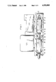
- FIG. 1 is a side view of a power thermo-coupling unit
- FIG. 2 is a section view on a horizontal plane in which the muffler and heat exchanger components lie.
- FIG. 1 is a side view of a power thermo-coupling unit incorporating the present invention.
- An engine and generator set consisting of an engine 2 drivingly connected to a generator 3, is elastically supported on a unit pad or support 1.
- Working machines other than an engine and generator unit may also be thus supported.
- the unit support 1 consists of a rectangular frame having top, bottom and end walls defining openings 11 on both its lateral sides.
- a central column 8 extends laterally and vertically between the top and bottom walls and divides the interior of the unit support into two adjacent compartments.
- a muffler 4, 5 and an exhaust gas heat exchanger 6, 7 are supported and positioned parallel to the longitudinal vertical plane of the generator set and to the longitudinal sides of the support unit 1.
- the muffler 4, 5 and.. the exhaust gas heat exchanger 6, 7 each consist of two separable components connected to each other by connecting pieces 10 having flanged connections with the related components.
- the connecting pieces 10 extend through longitudinal openings in the central column 8 and consist of a pipe with radially outwardly extending flanges at each end which are secured to flanges on the separable components by suitable releasable fastening means shown at 13:
- FIG. 2 illustrates removability of the components, which is an important feature of the invention.
- the two components of the muffler 4, 5 consist of a reflection chamber 4 and an absorption chamber 5, with the absorption chamber 5 series connected in downstream relation to the reflection chamber 4.
- the direction of flow is indicated by arrows in FIG. 2.
- the exhaust gas heat exchanger components 6, 7 are series connected downstream of the muffler 4, 5 and are disposed parallel to the muffler 4, 5.
- a U-shaped connector changes the direction of the flow from the muffler 4, 5 one hundred and eighty degrees so that the exhaust gases flow through the heat exchanger 6, 7 in an opposite parallel direction to its flow through the muffler 4, 5.
- the low-temperature component 6 is arranged downstream in the direction of flow from the high-temperature component 7.
- Support brackets 12 are provided on the components by which the components are secured to the unit support by releasable fasteners, not shown. In order to facilitate easy sliding removal of the components from the unit support 1, the brackets 12 are guided by tracks shown at 14. Thus the components with their brackets 12 may be slid like a shelf or drawer from the unit support 1.
- This invention provides a power thermo-coupling unit which is compact, easy to maintain and cost effective.
Abstract
Description
Claims (11)
Applications Claiming Priority (2)
| Application Number | Priority Date | Filing Date | Title |
|---|---|---|---|
| DE19873708238 DE3708238A1 (en) | 1987-03-16 | 1987-03-16 | POWER AND HEAT COUPLING SYSTEM |
| DE3708238 | 1987-03-16 |
Publications (1)
| Publication Number | Publication Date |
|---|---|
| US4921040A true US4921040A (en) | 1990-05-01 |
Family
ID=6323035
Family Applications (1)
| Application Number | Title | Priority Date | Filing Date |
|---|---|---|---|
| US07/166,924 Expired - Fee Related US4921040A (en) | 1987-03-16 | 1988-03-11 | Power thermo-coupling unit |
Country Status (3)
| Country | Link |
|---|---|
| US (1) | US4921040A (en) |
| EP (1) | EP0283763B1 (en) |
| DE (2) | DE3708238A1 (en) |
Cited By (10)
| Publication number | Priority date | Publication date | Assignee | Title |
|---|---|---|---|---|
| US5101886A (en) * | 1989-04-07 | 1992-04-07 | Motoren-Werke Mannheim Ag | Combination power and heat unit |
| US20030121919A1 (en) * | 2001-12-29 | 2003-07-03 | United States Can Company | Connector for use in packaging aerosol containers |
| US20040005318A1 (en) * | 2002-04-12 | 2004-01-08 | Medarex, Inc. | Methods of treatment using CTLA-4 antibodies |
| US6682736B1 (en) | 1998-12-23 | 2004-01-27 | Abgenix, Inc. | Human monoclonal antibodies to CTLA-4 |
| US20040228858A1 (en) * | 1998-12-23 | 2004-11-18 | Pfizer Inc. | Human monoclonal antibodies to CTLA-4 |
| US6984720B1 (en) | 1999-08-24 | 2006-01-10 | Medarex, Inc. | Human CTLA-4 antibodies |
| US20060037351A1 (en) * | 2004-08-17 | 2006-02-23 | Lg Electronics Inc. | Cogeneration system and exhaust gas heat exchanger assembly thereof |
| WO2009043222A1 (en) * | 2007-09-30 | 2009-04-09 | Wuxi Kipor Power Co., Ltd | An exhaust noise damping system for a silencing dynamotor set |
| US7605238B2 (en) | 1999-08-24 | 2009-10-20 | Medarex, Inc. | Human CTLA-4 antibodies and their uses |
| US9062111B2 (en) | 2005-12-07 | 2015-06-23 | Medarex, L.L.C. | CTLA-4 antibody dosage escalation regimens |
Families Citing this family (1)
| Publication number | Priority date | Publication date | Assignee | Title |
|---|---|---|---|---|
| DE19744178A1 (en) * | 1997-10-07 | 1999-04-08 | Roland Weidner | Exhaust gas heat exchanger with integral silencers for thermal power stations |
Citations (9)
| Publication number | Priority date | Publication date | Assignee | Title |
|---|---|---|---|---|
| US115870A (en) * | 1871-06-13 | Improvement im blast-heating furnaces or xvems | ||
| FR914203A (en) * | 1945-03-30 | 1946-10-02 | Moteurs Lab Et | Improvements to test facilities, particularly for engines |
| US2673446A (en) * | 1952-09-26 | 1954-03-30 | Salardi Mary De | Apparatus for processing combustion gases |
| US2801828A (en) * | 1954-11-08 | 1957-08-06 | Hanlon & Wilson Co | Heat exchanger, especially for airplanes |
| US3317001A (en) * | 1966-05-16 | 1967-05-02 | Walker Mfg Co | Muffler |
| US3500954A (en) * | 1969-03-13 | 1970-03-17 | Walker Mfg Co | Exhaust silencing system |
| JPS5417416A (en) * | 1977-07-11 | 1979-02-08 | Toyota Motor Corp | Device for preventing catalyst overheat |
| FR2550820A1 (en) * | 1983-08-18 | 1985-02-22 | Jourdan Charles | EXHAUST DEVICE FOR INTERNAL COMBUSTION ENGINE |
| US4645031A (en) * | 1984-04-13 | 1987-02-24 | Nissan Motor Company, Limited | Exhaust system for an internal combustion engine |
Family Cites Families (6)
| Publication number | Priority date | Publication date | Assignee | Title |
|---|---|---|---|---|
| FR1472876A (en) * | 1966-03-31 | 1967-03-10 | Gillet Kg Heinrich | Exhaust silencer for combustion engine |
| DE1476642A1 (en) * | 1966-05-14 | 1970-03-19 | Wohnungsbedarf Gmbh | Drive unit |
| DE1476538A1 (en) * | 1966-12-16 | 1970-09-17 | Hanning Elektro Werke | Portable power supply unit |
| DE2731583A1 (en) * | 1977-07-13 | 1979-01-18 | Maschf Augsburg Nuernberg Ag | ASSEMBLY GROUP OF A HEATING PLANT |
| DE2919237A1 (en) * | 1979-05-12 | 1980-11-27 | Motoren Werke Mannheim Ag | House heat pump with IC engine driven compressor - has standby alternator also driven by IC engine in emergencies |
| US4393656A (en) * | 1980-11-07 | 1983-07-19 | Anderson Forest L | Waste heat recovery system for an internal combustion engine |
-
1987
- 1987-03-16 DE DE19873708238 patent/DE3708238A1/en not_active Withdrawn
-
1988
- 1988-02-29 DE DE8888102988T patent/DE3860313D1/en not_active Expired - Fee Related
- 1988-02-29 EP EP88102988A patent/EP0283763B1/en not_active Expired - Lifetime
- 1988-03-11 US US07/166,924 patent/US4921040A/en not_active Expired - Fee Related
Patent Citations (9)
| Publication number | Priority date | Publication date | Assignee | Title |
|---|---|---|---|---|
| US115870A (en) * | 1871-06-13 | Improvement im blast-heating furnaces or xvems | ||
| FR914203A (en) * | 1945-03-30 | 1946-10-02 | Moteurs Lab Et | Improvements to test facilities, particularly for engines |
| US2673446A (en) * | 1952-09-26 | 1954-03-30 | Salardi Mary De | Apparatus for processing combustion gases |
| US2801828A (en) * | 1954-11-08 | 1957-08-06 | Hanlon & Wilson Co | Heat exchanger, especially for airplanes |
| US3317001A (en) * | 1966-05-16 | 1967-05-02 | Walker Mfg Co | Muffler |
| US3500954A (en) * | 1969-03-13 | 1970-03-17 | Walker Mfg Co | Exhaust silencing system |
| JPS5417416A (en) * | 1977-07-11 | 1979-02-08 | Toyota Motor Corp | Device for preventing catalyst overheat |
| FR2550820A1 (en) * | 1983-08-18 | 1985-02-22 | Jourdan Charles | EXHAUST DEVICE FOR INTERNAL COMBUSTION ENGINE |
| US4645031A (en) * | 1984-04-13 | 1987-02-24 | Nissan Motor Company, Limited | Exhaust system for an internal combustion engine |
Cited By (18)
| Publication number | Priority date | Publication date | Assignee | Title |
|---|---|---|---|---|
| US5101886A (en) * | 1989-04-07 | 1992-04-07 | Motoren-Werke Mannheim Ag | Combination power and heat unit |
| US6682736B1 (en) | 1998-12-23 | 2004-01-27 | Abgenix, Inc. | Human monoclonal antibodies to CTLA-4 |
| US20040228858A1 (en) * | 1998-12-23 | 2004-11-18 | Pfizer Inc. | Human monoclonal antibodies to CTLA-4 |
| US8017114B2 (en) | 1999-08-24 | 2011-09-13 | Medarex, Inc. | Human CTLA-4 antibodies and their uses |
| US7605238B2 (en) | 1999-08-24 | 2009-10-20 | Medarex, Inc. | Human CTLA-4 antibodies and their uses |
| US6984720B1 (en) | 1999-08-24 | 2006-01-10 | Medarex, Inc. | Human CTLA-4 antibodies |
| US8784815B2 (en) | 1999-08-24 | 2014-07-22 | Medarex, L.L.C. | Human CTLA-4 antibodies and their uses |
| US8318916B2 (en) | 1999-08-24 | 2012-11-27 | Medarex, Inc. | Human CTLA-4 antibodies and their uses |
| US20100047244A1 (en) * | 1999-08-24 | 2010-02-25 | Medarex, Inc. | Human CTLA-4 Antibodies and Their Uses |
| US20030121919A1 (en) * | 2001-12-29 | 2003-07-03 | United States Can Company | Connector for use in packaging aerosol containers |
| US7452535B2 (en) | 2002-04-12 | 2008-11-18 | Medarex, Inc. | Methods of treatment using CTLA-4 antibodies |
| US20090117037A1 (en) * | 2002-04-12 | 2009-05-07 | Medarex, Inc. | Methods Of Treatment Using CTLA-4 Antibodies |
| US8142778B2 (en) | 2002-04-12 | 2012-03-27 | Medarex, Inc. | Methods of treatment using CTLA-4 antibodies |
| US20040005318A1 (en) * | 2002-04-12 | 2004-01-08 | Medarex, Inc. | Methods of treatment using CTLA-4 antibodies |
| US20060037351A1 (en) * | 2004-08-17 | 2006-02-23 | Lg Electronics Inc. | Cogeneration system and exhaust gas heat exchanger assembly thereof |
| US9062111B2 (en) | 2005-12-07 | 2015-06-23 | Medarex, L.L.C. | CTLA-4 antibody dosage escalation regimens |
| US9573999B2 (en) | 2005-12-07 | 2017-02-21 | E. R. Squibb & Sons, L.L.C. | CTLA-4 antibody dosage escalation regimens |
| WO2009043222A1 (en) * | 2007-09-30 | 2009-04-09 | Wuxi Kipor Power Co., Ltd | An exhaust noise damping system for a silencing dynamotor set |
Also Published As
| Publication number | Publication date |
|---|---|
| EP0283763A1 (en) | 1988-09-28 |
| EP0283763B1 (en) | 1990-07-18 |
| DE3860313D1 (en) | 1990-08-23 |
| DE3708238A1 (en) | 1988-09-29 |
Similar Documents
| Publication | Publication Date | Title |
|---|---|---|
| US4921040A (en) | Power thermo-coupling unit | |
| US5448986A (en) | Heat exchanger | |
| JPH0220422A (en) | Refrigeration unit for transporting zero cube | |
| DE3150001C2 (en) | Piston internal combustion engine with supercharging | |
| GB2443421A (en) | Modular compressor | |
| WO2018053860A1 (en) | Air handling unit | |
| US9470460B2 (en) | Heat exchanger for power system | |
| CN210141172U (en) | Frameless cooling module | |
| US2782008A (en) | Heat exchangers for fluids | |
| US5295473A (en) | Furnace | |
| KR930011918B1 (en) | Coke dry cooling plant | |
| KR920021850A (en) | Combustor-turbine unit and compressor merging method and system | |
| US2773364A (en) | Cooler unit | |
| US3712286A (en) | Gas or oil fired heat exchanger for forced air heating unit | |
| EP1764495A2 (en) | Method and apparatus for housing gas turbine engines | |
| JP3520503B2 (en) | Oil water heater burner unit | |
| US2439109A (en) | Air-heating furnace with selective | |
| JP2006292330A (en) | Bottom structure for engine-driven air conditioner | |
| US5101886A (en) | Combination power and heat unit | |
| US2290978A (en) | Warm air furnace | |
| SE506516C2 (en) | Exhaust silencer for motor vehicles | |
| SU1756745A1 (en) | Hot-water boiler | |
| RU11319U1 (en) | RADIATOR ISLAND | |
| CN219176444U (en) | Air inlet and exhaust system of gas generator set | |
| WO2018156623A1 (en) | Modular gas turbine inlet cooling systems |
Legal Events
| Date | Code | Title | Description |
|---|---|---|---|
| AS | Assignment |
Owner name: MOTOREN-WERKE MANNHEIM AG, CARL-BENZ-STRASSE 5 680 Free format text: ASSIGNMENT OF ASSIGNORS INTEREST.;ASSIGNORS:UERUENDUEL, CELAL;ZACHARIAS, FRIEDEMANN;REEL/FRAME:004910/0803;SIGNING DATES FROM 19880529 TO 19880530 Owner name: MOTOREN-WERKE MANNHEIM AG,GERMANY Free format text: ASSIGNMENT OF ASSIGNORS INTEREST;ASSIGNORS:UERUENDUEL, CELAL;ZACHARIAS, FRIEDEMANN;SIGNING DATES FROM 19880529 TO 19880530;REEL/FRAME:004910/0803 |
|
| FEPP | Fee payment procedure |
Free format text: PAYOR NUMBER ASSIGNED (ORIGINAL EVENT CODE: ASPN); ENTITY STATUS OF PATENT OWNER: LARGE ENTITY |
|
| CC | Certificate of correction | ||
| REMI | Maintenance fee reminder mailed | ||
| LAPS | Lapse for failure to pay maintenance fees | ||
| FP | Lapsed due to failure to pay maintenance fee |
Effective date: 19940501 |
|
| STCH | Information on status: patent discontinuation |
Free format text: PATENT EXPIRED DUE TO NONPAYMENT OF MAINTENANCE FEES UNDER 37 CFR 1.362 |