US4925598A - Aerator for industrial and domestic wastewaters - Google Patents
Aerator for industrial and domestic wastewaters Download PDFInfo
- Publication number
- US4925598A US4925598A US07/204,721 US20472188A US4925598A US 4925598 A US4925598 A US 4925598A US 20472188 A US20472188 A US 20472188A US 4925598 A US4925598 A US 4925598A
- Authority
- US
- United States
- Prior art keywords
- stator
- rotor
- ducts
- diameter
- shell
- Prior art date
- Legal status (The legal status is an assumption and is not a legal conclusion. Google has not performed a legal analysis and makes no representation as to the accuracy of the status listed.)
- Expired - Lifetime
Links
Images


Classifications
-
- C—CHEMISTRY; METALLURGY
- C02—TREATMENT OF WATER, WASTE WATER, SEWAGE, OR SLUDGE
- C02F—TREATMENT OF WATER, WASTE WATER, SEWAGE, OR SLUDGE
- C02F3/00—Biological treatment of water, waste water, or sewage
- C02F3/02—Aerobic processes
- C02F3/12—Activated sludge processes
- C02F3/20—Activated sludge processes using diffusers
- C02F3/205—Moving, e.g. rotary, diffusers; Stationary diffusers with moving, e.g. rotary, distributors
-
- B—PERFORMING OPERATIONS; TRANSPORTING
- B01—PHYSICAL OR CHEMICAL PROCESSES OR APPARATUS IN GENERAL
- B01F—MIXING, e.g. DISSOLVING, EMULSIFYING OR DISPERSING
- B01F25/00—Flow mixers; Mixers for falling materials, e.g. solid particles
- B01F25/20—Jet mixers, i.e. mixers using high-speed fluid streams
- B01F25/21—Jet mixers, i.e. mixers using high-speed fluid streams with submerged injectors, e.g. nozzles, for injecting high-pressure jets into a large volume or into mixing chambers
-
- B—PERFORMING OPERATIONS; TRANSPORTING
- B01—PHYSICAL OR CHEMICAL PROCESSES OR APPARATUS IN GENERAL
- B01F—MIXING, e.g. DISSOLVING, EMULSIFYING OR DISPERSING
- B01F23/00—Mixing according to the phases to be mixed, e.g. dispersing or emulsifying
- B01F23/20—Mixing gases with liquids
- B01F23/23—Mixing gases with liquids by introducing gases into liquid media, e.g. for producing aerated liquids
- B01F23/233—Mixing gases with liquids by introducing gases into liquid media, e.g. for producing aerated liquids using driven stirrers with completely immersed stirring elements
- B01F23/2331—Mixing gases with liquids by introducing gases into liquid media, e.g. for producing aerated liquids using driven stirrers with completely immersed stirring elements characterised by the introduction of the gas along the axis of the stirrer or along the stirrer elements
- B01F23/23311—Mixing gases with liquids by introducing gases into liquid media, e.g. for producing aerated liquids using driven stirrers with completely immersed stirring elements characterised by the introduction of the gas along the axis of the stirrer or along the stirrer elements through a hollow stirrer axis
-
- B—PERFORMING OPERATIONS; TRANSPORTING
- B01—PHYSICAL OR CHEMICAL PROCESSES OR APPARATUS IN GENERAL
- B01F—MIXING, e.g. DISSOLVING, EMULSIFYING OR DISPERSING
- B01F23/00—Mixing according to the phases to be mixed, e.g. dispersing or emulsifying
- B01F23/20—Mixing gases with liquids
- B01F23/23—Mixing gases with liquids by introducing gases into liquid media, e.g. for producing aerated liquids
- B01F23/233—Mixing gases with liquids by introducing gases into liquid media, e.g. for producing aerated liquids using driven stirrers with completely immersed stirring elements
- B01F23/2331—Mixing gases with liquids by introducing gases into liquid media, e.g. for producing aerated liquids using driven stirrers with completely immersed stirring elements characterised by the introduction of the gas along the axis of the stirrer or along the stirrer elements
- B01F23/23314—Mixing gases with liquids by introducing gases into liquid media, e.g. for producing aerated liquids using driven stirrers with completely immersed stirring elements characterised by the introduction of the gas along the axis of the stirrer or along the stirrer elements through a hollow stirrer element
-
- B—PERFORMING OPERATIONS; TRANSPORTING
- B01—PHYSICAL OR CHEMICAL PROCESSES OR APPARATUS IN GENERAL
- B01F—MIXING, e.g. DISSOLVING, EMULSIFYING OR DISPERSING
- B01F23/00—Mixing according to the phases to be mixed, e.g. dispersing or emulsifying
- B01F23/20—Mixing gases with liquids
- B01F23/23—Mixing gases with liquids by introducing gases into liquid media, e.g. for producing aerated liquids
- B01F23/233—Mixing gases with liquids by introducing gases into liquid media, e.g. for producing aerated liquids using driven stirrers with completely immersed stirring elements
- B01F23/2334—Mixing gases with liquids by introducing gases into liquid media, e.g. for producing aerated liquids using driven stirrers with completely immersed stirring elements provided with stationary guiding means surrounding at least partially the stirrer
- B01F23/23342—Mixing gases with liquids by introducing gases into liquid media, e.g. for producing aerated liquids using driven stirrers with completely immersed stirring elements provided with stationary guiding means surrounding at least partially the stirrer the stirrer being of the centrifugal type, e.g. with a surrounding stator
-
- B—PERFORMING OPERATIONS; TRANSPORTING
- B01—PHYSICAL OR CHEMICAL PROCESSES OR APPARATUS IN GENERAL
- B01F—MIXING, e.g. DISSOLVING, EMULSIFYING OR DISPERSING
- B01F23/00—Mixing according to the phases to be mixed, e.g. dispersing or emulsifying
- B01F23/20—Mixing gases with liquids
- B01F23/23—Mixing gases with liquids by introducing gases into liquid media, e.g. for producing aerated liquids
- B01F23/233—Mixing gases with liquids by introducing gases into liquid media, e.g. for producing aerated liquids using driven stirrers with completely immersed stirring elements
- B01F23/2335—Mixing gases with liquids by introducing gases into liquid media, e.g. for producing aerated liquids using driven stirrers with completely immersed stirring elements characterised by the direction of introduction of the gas relative to the stirrer
- B01F23/23352—Mixing gases with liquids by introducing gases into liquid media, e.g. for producing aerated liquids using driven stirrers with completely immersed stirring elements characterised by the direction of introduction of the gas relative to the stirrer the gas moving perpendicular to the axis of rotation
-
- B—PERFORMING OPERATIONS; TRANSPORTING
- B01—PHYSICAL OR CHEMICAL PROCESSES OR APPARATUS IN GENERAL
- B01F—MIXING, e.g. DISSOLVING, EMULSIFYING OR DISPERSING
- B01F23/00—Mixing according to the phases to be mixed, e.g. dispersing or emulsifying
- B01F23/20—Mixing gases with liquids
- B01F23/23—Mixing gases with liquids by introducing gases into liquid media, e.g. for producing aerated liquids
- B01F23/233—Mixing gases with liquids by introducing gases into liquid media, e.g. for producing aerated liquids using driven stirrers with completely immersed stirring elements
- B01F23/2336—Mixing gases with liquids by introducing gases into liquid media, e.g. for producing aerated liquids using driven stirrers with completely immersed stirring elements characterised by the location of the place of introduction of the gas relative to the stirrer
- B01F23/23364—Mixing gases with liquids by introducing gases into liquid media, e.g. for producing aerated liquids using driven stirrers with completely immersed stirring elements characterised by the location of the place of introduction of the gas relative to the stirrer the gas being introduced between the stirrer elements
-
- B—PERFORMING OPERATIONS; TRANSPORTING
- B01—PHYSICAL OR CHEMICAL PROCESSES OR APPARATUS IN GENERAL
- B01F—MIXING, e.g. DISSOLVING, EMULSIFYING OR DISPERSING
- B01F23/00—Mixing according to the phases to be mixed, e.g. dispersing or emulsifying
- B01F23/40—Mixing liquids with liquids; Emulsifying
- B01F23/45—Mixing liquids with liquids; Emulsifying using flow mixing
- B01F23/454—Mixing liquids with liquids; Emulsifying using flow mixing by injecting a mixture of liquid and gas
-
- Y—GENERAL TAGGING OF NEW TECHNOLOGICAL DEVELOPMENTS; GENERAL TAGGING OF CROSS-SECTIONAL TECHNOLOGIES SPANNING OVER SEVERAL SECTIONS OF THE IPC; TECHNICAL SUBJECTS COVERED BY FORMER USPC CROSS-REFERENCE ART COLLECTIONS [XRACs] AND DIGESTS
- Y02—TECHNOLOGIES OR APPLICATIONS FOR MITIGATION OR ADAPTATION AGAINST CLIMATE CHANGE
- Y02W—CLIMATE CHANGE MITIGATION TECHNOLOGIES RELATED TO WASTEWATER TREATMENT OR WASTE MANAGEMENT
- Y02W10/00—Technologies for wastewater treatment
- Y02W10/10—Biological treatment of water, waste water, or sewage
Definitions
- the present invention relates to the aerating of domestic and industrial wastewaters by means of an aerator to be placed on the bottom of the oxidation pond.
- the invention relates to the structure of the stator of the aerator.
- Sewage aerators are generally divided into surface and bottom aerators.
- a bottom aerator where the necessary equipment, i.e. hydraulics, ejectors and blower is combined to form a uniform entity.
- the air absorbed by the apparatus is evenly distributed in the ring casing and pumped in small bubbles, mixed in the water, into the pond via the ejectors.
- the number of ejectors is 10-24.
- the FI patent application 862145 discloses an aerator comprising a rotor and a surrounding stator which is provided with a closed ring and is formed of flow channels which are rectangular in cross-section.
- the adjacent vertical bounding surfaces of immediately adjacent flow channels are shifted further away from each other towards the outer circumference of the stator, and the vertical bounding surfaces of each flow channel are parallel, with a deviation of 7° at the most.
- the flow channels are formed for instance by means of U-profiles installed on circular plates.
- the FI patent application 842029 introduces a bottom aerator formed of a stator and a conical rotor provided with rotor blades and air inlets placed in the rotor housing behind the rotor blades.
- the apparatus functions effectively up to a certain amount of air, but when attempts are made for feeding very large gas amounts, the rotor starts to rotate in an "air bubble", and as is well known, this is extremely harmful for the rotor because it may cause torsional damage to the rotor shaft, and in cany case it leads to a decrease in the efficiency.
- aerator apparatus wherein a rotor--of the same type as in the FI application 842029--is surrounded by a stator which comprises a stator shell structure, legs attached to the shell structure and extending to the bottom of the pond, as well as triangular blade members fastened to the legs.
- the flow ducts can be either radially or tangentially directed with respect to the rotor.
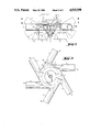
- FIG. 1 is an oblique axonometric illustration of the aerator of the invention
- FIG. 2 is a vertical cross-section of the stator-rotor system, when the stator ducts are installed tangentially;
- FIG. 3 is a top-view illustration of the rotor-stator system of FIG. 2;
- FIG. 4 is a top-view illustration of the rotor-stator system, when the stator ducts are installed radially;
- FIG. 5 is a side elevation of the rotor-stator system of FIG. 2;
- FIG. 6 is a bottom plan view of the rotor
- FIG. 7 is a vertical sectional view of the rotor.
- FIG. 1 shows that the gas is supplied into the aerator via the supply pipe 1 to the bottom part of the operating unit 2. Therefrom the gas proceeds through a hollow rotor shaft 13 (FIG. 5) to within the conical rotor 3, and is discharged into liquid via the opening 14 provided behind the rotor blades.
- the structure of the rotor will be described in further detail below
- the stator comprises the shell structure 4 installed around the top part of the rotor, the support legs 5 directed downwards therefrom, the triangular blade members 6 attached to the said legs, and the stator ducts 7 starting from the outer edge of the shell structure.
- the stator ducts 7, which are supported relative to the shell structure 4 by triangle gusset plates 12, can be installed either radially or tangentially with respect to the rotor, but best results have been achieved with tangentially installed ducts.
- the gas, such as air, discharged from the openings of the rotor 3, is mixed into the surrounding slurry in the space left between the rotor 3 and the stator shell 4.
- the top opening 8 of the shell structure 4 is located above the top part of the rotor, and the diameter of the top opening 8 is 0.6-0.9 times the diameter of the top part of the rotor, advantageously the diameter of the top part of the rotor multiplied by roughly 0.7.
- the cross-gap between the rotor and the shell structure in the top part of the shell is 5-20%, advantageously about 10% of the rotor height.
- the diameter of the bottom opening 9 of the shell structure is 1-2 times the diameter of the rotor, advantageously 1.1-1.5 times the rotor diameter. (For the sake of clarity, the rotor diameter always means the diameter of the top part of the rotor.)
- the aerated liquid can always be conducted away from the immediate vicinity of the rotor, so that the effect of the aerating extends to a wider area.
- Another advantage is, as was already pointed out, that through the ducts the air can be lead out of the rotor space and thus the rotor can be prevented from rotating in an "air bubble".
- the height of the stator shell structure and the diameter of the stator ducts can somewhat be adjusted according to the needs, but advantageously it remains within a range of 0.20-0.50 times the rotor height. If the diameter of the ducts is too small, only part of the aerated slurry flows through the ducts, but the rest flows outside and thus "kills" the duct flow.
- stator shell and the stator ducts are placed in a horizontal position, but this is by no means necessary, because--as is indicated by the dotted lines in FIG. 2--the shell and the ducts can be installed with an inclination of 0°-30° upwards or downwards with respect to the horizontal level.
- the number of the stator ducts may vary, for instance between 3 and 15, but it is pointed out that if the number of ducts grows too high, the flowing speed inside the ducts remains low, wherefore the most profitable amount in practice has proved to be 4-12.
- the length of the stator ducts may also vary somewhat so that the diameter of the circle formed by the outer ends 10 of the ducts 7 is 2-5 times the rotor diameter. If the ducts are too long, the bubbles formed in the aerating process are combined inside the ducts and cause the hazard mentioned above. Back-eddies may also be formed in ducts which are too long, and a large amount of air contained in the ducts may cause a lifting effect in the whole aerator apparatus.
- stator ducts 7 are described to be round. Without departing from the spirit of the invention, ducts of some other shape, such as rectangular ducts, can also be employed.
- the blade members 6 attached to the stator legs 5 are advantageously triangular and narrowed towards the top. According to FIG. 2, the blade members 6 are installed so that they are advantageously directed inwards with respect to the legs 5, but the dotted lines marked in the same drawing indicate that the blade members 6 can also be installed to point outwards with respect to the stator legs 5.
- the number of the legs may also vary, but is suitably 3-6. If the blade members of the stator legs are omitted, the slurry easily tends to twirl in the pond, and the use of the energy of the apparatus is very unstable.
- the stator legs are fastened to the shell structure 4.
- the structure of the rotor is illustrated in detail in FIGS. 5, 6 and 7.
- the conical rotor 3 is connected to the hollow drive shaft 13, and comprises a rotor housing 15 in the form of a downward narrowing cone having rotor blades 16 projecting radially therefrom.
- the blades 16 are generally trapezoidal, being broader at the top of the rotor and narrowing smoothly in the downward direction.
- the openings 14 are formed in the rotor housing 15.
- the vertical extent of the openings 14 is not as great as the that of the rotor housing 15, but the openings 14 preferably extend over about two thirds of the height of the housing so that the bottom of each opening is somewhat above the point of the rotor housing.
- a second cone 17 which narrows in the upward direction.
- the bottom of the inner cone 17 is secured to the interior of the rotor housing 15 about one third of the way up the housing 15 from its bottom.
- a cover plate 18 extends over the upper part of the rotor housing 15. The height of the inner cone 17 is such that the top of the inner cone is below the cover plate 18.
- FIGS. 6 and 7 show that the cover plate 18 extends radially at least as far as the blades 16.
- the aerator In operation, the aerator is placed in a pond of a slurry to be aerated, air is supplied to the hollow rotor shaft 13 through the supply pipe 1, and the rotor is driven to rotate by a motor included in the operating unit 2. As the rotor rotates and agitates the slurry, air is expelled through the openings 14, which are placed behind the rotor blades 16 in the direction of rotation of the rotor. The air leaving the rotor through the openings 14 aerates the slurry, and the aerated slurry leaves the shell structure 4 through the stator ducts 7 and slurry is drawn upwardly into the rotor.
- the inner cone 17, located inside the rotor housing 15, ensures that slurry does not remain inside the rotor housing but is expelled by centrifugal force.
- the inner cone 17 also controls supply of air to the opening 14.
- the increase in capacity when comparing the maximum capacities of apparatuses of the same size, has been 60%. It is pointed out that when employing the apparatus of the present invention, a large amount of oxygen can be fed into the slurry to be aerated.
Landscapes
- Chemical & Material Sciences (AREA)
- Chemical Kinetics & Catalysis (AREA)
- Life Sciences & Earth Sciences (AREA)
- Engineering & Computer Science (AREA)
- Microbiology (AREA)
- Hydrology & Water Resources (AREA)
- Biodiversity & Conservation Biology (AREA)
- Environmental & Geological Engineering (AREA)
- Water Supply & Treatment (AREA)
- Organic Chemistry (AREA)
- Aeration Devices For Treatment Of Activated Polluted Sludge (AREA)
- Mixers Of The Rotary Stirring Type (AREA)
- Steroid Compounds (AREA)
- Fertilizers (AREA)
- Processing Of Solid Wastes (AREA)
Abstract
Description
______________________________________
         domestic wastewater
                      industrial wastewater
______________________________________
prior art  100-200        200-400
invention  50- 70         100-200
______________________________________
______________________________________
prior art              15-25
present invention      20-40
______________________________________
______________________________________
prior art              1.8-2.0
present invention      2.0-2.5
______________________________________
Claims (13)
Applications Claiming Priority (2)
| Application Number | Priority Date | Filing Date | Title |
|---|---|---|---|
| FI872615A FI81077C (en) | 1987-06-11 | 1987-06-11 | LUFTNINGSANORDNING FOER AVFALLSVATTEN FRAON INDUSTRI OCH BEBYGGELSE. |
| FI872615 | 1987-06-11 |
Publications (1)
| Publication Number | Publication Date |
|---|---|
| US4925598A true US4925598A (en) | 1990-05-15 |
Family
ID=8524658
Family Applications (1)
| Application Number | Title | Priority Date | Filing Date |
|---|---|---|---|
| US07/204,721 Expired - Lifetime US4925598A (en) | 1987-06-11 | 1988-06-10 | Aerator for industrial and domestic wastewaters |
Country Status (7)
| Country | Link |
|---|---|
| US (1) | US4925598A (en) |
| EP (1) | EP0294736B1 (en) |
| AT (1) | ATE58711T1 (en) |
| CA (1) | CA1330461C (en) |
| DE (1) | DE3861168D1 (en) |
| DK (1) | DK170116B1 (en) |
| FI (1) | FI81077C (en) |
Cited By (13)
| Publication number | Priority date | Publication date | Assignee | Title |
|---|---|---|---|---|
| US5356570A (en) * | 1992-09-10 | 1994-10-18 | Heinrich Frings Gmbh & Co Kg | Apparatus for aerating liquids |
| US5358671A (en) * | 1992-07-17 | 1994-10-25 | Outokumpu Mintec Oy | Aerator device |
| US5458816A (en) * | 1993-09-29 | 1995-10-17 | Heinrich Frings Gmbh & Co. Kg | Apparatus for aerating and/or anaerobically mixing liquids |
| US5800742A (en) * | 1996-12-30 | 1998-09-01 | Cheng; Mao-Chung | Underwater air delivering device |
| US6318705B1 (en) * | 2000-01-14 | 2001-11-20 | Jet, Inc. | Aspirator |
| US6394430B1 (en) * | 1998-10-13 | 2002-05-28 | Ekato Rühr-und Mischtechnik GmbH | Auto-aspirating rotational dispersion device |
| US6712980B1 (en) * | 1999-01-15 | 2004-03-30 | Gefle Virvelteknik Ab | Device and method for the treatment of contaminated media |
| US20040154178A1 (en) * | 2001-04-11 | 2004-08-12 | Peter Herkt | Length sensor |
| US20080173727A1 (en) * | 2007-01-02 | 2008-07-24 | Trent Lydic | Aspirator |
| US20110156290A1 (en) * | 2009-12-30 | 2011-06-30 | David Allen Wensloff | Medium Orbital Flow Oxygenator |
| DE102015216517A1 (en) * | 2015-08-28 | 2017-03-02 | Aktiebolaget Skf | contraption |
| CN110407318A (en) * | 2019-07-17 | 2019-11-05 | 上海世浦泰膜科技有限公司 | A kind of porous while aerator |
| DE102019101934A1 (en) * | 2019-01-25 | 2020-07-30 | EKATO Rühr- und Mischtechnik GmbH | Stirrer device |
Families Citing this family (2)
| Publication number | Priority date | Publication date | Assignee | Title |
|---|---|---|---|---|
| US5152888A (en) * | 1991-10-24 | 1992-10-06 | Net Co., Ltd. | Apparatus for treatment of organic waste water and contactor for use therein |
| ITMC20050142A1 (en) * | 2005-12-27 | 2007-06-28 | Faggiolati Pumps S P A | VENTILATION MACHINE FOR WASTEWATER TREATMENT PLANTS. |
Citations (8)
| Publication number | Priority date | Publication date | Assignee | Title |
|---|---|---|---|---|
| DE234697C (en) * | ||||
| US2415585A (en) * | 1938-03-31 | 1947-02-11 | Automatic Holding Company Sa | Apparatus for the instantaneous preparation of iced foodstuffs such as creams of the like |
| US2892543A (en) * | 1956-02-27 | 1959-06-30 | Mining Process & Patent Co | Aerator assembly with pulp elevating discharge |
| NL7108614A (en) * | 1971-06-22 | 1972-12-28 | ||
| US3920779A (en) * | 1973-12-17 | 1975-11-18 | Tait Inc | Submersible aerator |
| US4283357A (en) * | 1978-02-28 | 1981-08-11 | Trodhjems Mek. Versted A/S | Device for distribution of a gas in a liquid medium |
| US4720361A (en) * | 1985-02-20 | 1988-01-19 | Outokumpu Oy | Immersible aerator and/or mixer apparatus |
| US4800017A (en) * | 1987-04-16 | 1989-01-24 | Dorr-Oliver Incorporated | Flotation mechanism |
Family Cites Families (2)
| Publication number | Priority date | Publication date | Assignee | Title |
|---|---|---|---|---|
| FR2411159A1 (en) * | 1977-12-06 | 1979-07-06 | Jeumont Schneider | Tank installation to inject gas into liq. esp. waste water - to be aerated via submerged rotor with hollow perforated blades |
| DE3321143A1 (en) * | 1983-06-10 | 1984-12-13 | Anton 8206 Bruckmühl Humpel | Device for treating liquids, in particular liquid manure, preferably situated in containers, and distribution device for this purpose |
-
1987
- 1987-06-11 FI FI872615A patent/FI81077C/en not_active IP Right Cessation
-
1988
- 1988-05-30 DK DK294888A patent/DK170116B1/en not_active IP Right Cessation
- 1988-06-06 AT AT88108987T patent/ATE58711T1/en not_active IP Right Cessation
- 1988-06-06 EP EP19880108987 patent/EP0294736B1/en not_active Expired - Lifetime
- 1988-06-06 DE DE8888108987T patent/DE3861168D1/en not_active Expired - Lifetime
- 1988-06-10 US US07/204,721 patent/US4925598A/en not_active Expired - Lifetime
- 1988-06-10 CA CA 569276 patent/CA1330461C/en not_active Expired - Lifetime
Patent Citations (8)
| Publication number | Priority date | Publication date | Assignee | Title |
|---|---|---|---|---|
| DE234697C (en) * | ||||
| US2415585A (en) * | 1938-03-31 | 1947-02-11 | Automatic Holding Company Sa | Apparatus for the instantaneous preparation of iced foodstuffs such as creams of the like |
| US2892543A (en) * | 1956-02-27 | 1959-06-30 | Mining Process & Patent Co | Aerator assembly with pulp elevating discharge |
| NL7108614A (en) * | 1971-06-22 | 1972-12-28 | ||
| US3920779A (en) * | 1973-12-17 | 1975-11-18 | Tait Inc | Submersible aerator |
| US4283357A (en) * | 1978-02-28 | 1981-08-11 | Trodhjems Mek. Versted A/S | Device for distribution of a gas in a liquid medium |
| US4720361A (en) * | 1985-02-20 | 1988-01-19 | Outokumpu Oy | Immersible aerator and/or mixer apparatus |
| US4800017A (en) * | 1987-04-16 | 1989-01-24 | Dorr-Oliver Incorporated | Flotation mechanism |
Cited By (16)
| Publication number | Priority date | Publication date | Assignee | Title |
|---|---|---|---|---|
| US5358671A (en) * | 1992-07-17 | 1994-10-25 | Outokumpu Mintec Oy | Aerator device |
| US5356570A (en) * | 1992-09-10 | 1994-10-18 | Heinrich Frings Gmbh & Co Kg | Apparatus for aerating liquids |
| US5458816A (en) * | 1993-09-29 | 1995-10-17 | Heinrich Frings Gmbh & Co. Kg | Apparatus for aerating and/or anaerobically mixing liquids |
| US5800742A (en) * | 1996-12-30 | 1998-09-01 | Cheng; Mao-Chung | Underwater air delivering device |
| US6394430B1 (en) * | 1998-10-13 | 2002-05-28 | Ekato Rühr-und Mischtechnik GmbH | Auto-aspirating rotational dispersion device |
| US6712980B1 (en) * | 1999-01-15 | 2004-03-30 | Gefle Virvelteknik Ab | Device and method for the treatment of contaminated media |
| US6318705B1 (en) * | 2000-01-14 | 2001-11-20 | Jet, Inc. | Aspirator |
| US7121013B2 (en) | 2001-04-11 | 2006-10-17 | Dr. Johannes Heidenhain Gmbh | Length sensor |
| US20040154178A1 (en) * | 2001-04-11 | 2004-08-12 | Peter Herkt | Length sensor |
| US20080173727A1 (en) * | 2007-01-02 | 2008-07-24 | Trent Lydic | Aspirator |
| US8056886B2 (en) * | 2007-01-02 | 2011-11-15 | Jet Inc. | Aspirator |
| US20110156290A1 (en) * | 2009-12-30 | 2011-06-30 | David Allen Wensloff | Medium Orbital Flow Oxygenator |
| DE102015216517A1 (en) * | 2015-08-28 | 2017-03-02 | Aktiebolaget Skf | contraption |
| DE102019101934A1 (en) * | 2019-01-25 | 2020-07-30 | EKATO Rühr- und Mischtechnik GmbH | Stirrer device |
| US11623185B2 (en) * | 2019-01-25 | 2023-04-11 | Ekato Rühr-und Mischtechnik GmbH | Stirring element device |
| CN110407318A (en) * | 2019-07-17 | 2019-11-05 | 上海世浦泰膜科技有限公司 | A kind of porous while aerator |
Also Published As
| Publication number | Publication date |
|---|---|
| EP0294736B1 (en) | 1990-11-28 |
| DK170116B1 (en) | 1995-05-29 |
| ATE58711T1 (en) | 1990-12-15 |
| DK294888A (en) | 1988-12-12 |
| FI81077B (en) | 1990-05-31 |
| EP0294736A1 (en) | 1988-12-14 |
| CA1330461C (en) | 1994-06-28 |
| DE3861168D1 (en) | 1991-01-10 |
| DK294888D0 (en) | 1988-05-30 |
| FI81077C (en) | 1990-09-10 |
| FI872615A (en) | 1988-12-12 |
| FI872615A0 (en) | 1987-06-11 |
Similar Documents
| Publication | Publication Date | Title |
|---|---|---|
| US4925598A (en) | Aerator for industrial and domestic wastewaters | |
| US2767965A (en) | Dual pumping agitation | |
| EP0015050B1 (en) | Fluids mixing apparatus | |
| US4681711A (en) | Method and apparatus for aeration of wastewater lagoons | |
| KR101566240B1 (en) | Aeration impeller and agitator for water treatment having the same | |
| US4844843A (en) | Waste water aerator having rotating compression blades | |
| KR100316317B1 (en) | Liquid mixing device | |
| JPH0133234B2 (en) | ||
| JPS6244967B2 (en) | ||
| AU2014211305A1 (en) | Stirred tank reactor | |
| US4207275A (en) | Mixing apparatus | |
| JP3160057B2 (en) | Stirring aeration device | |
| EA003898B1 (en) | Flotation mechanism and method for dispersing gas and controlling flow in a flotation cell | |
| US4551285A (en) | Flotation machine and aeration impeller | |
| KR20040097040A (en) | Submersible Aerator with the Encreased Capacity of Aeration and Ability of Diffusion | |
| FI87893C (en) | Methods of enriching ore suspension by means of vigorous preparatory mixing and simultaneous flotation and devices for carrying out this | |
| US4305894A (en) | Arrangement in apparatus for mixing gases with and dissolving gases in liquids | |
| US7404924B2 (en) | Flotation device | |
| EP0027911B1 (en) | Apparatus for contacting liquid with a gas | |
| JP4754586B2 (en) | Aeration stirrer | |
| EA005546B1 (en) | Flotation mechanism and cell | |
| JPH03229696A (en) | Air bubble generator | |
| HU188312B (en) | Mixing aerating device | |
| US5143600A (en) | Apparatus for feeding air into a flotation cell | |
| CA1056964A (en) | Apparatus for mixing a liquid with a gas in a vessel |
Legal Events
| Date | Code | Title | Description |
|---|---|---|---|
| AS | Assignment |
Owner name: OUTOKUMPU OY, TOOLOKATU 4, HELSINKI, FINLAND Free format text: ASSIGNMENT OF ASSIGNORS INTEREST.;ASSIGNORS:KIVISTO, TUOMO V. J.;KOHO, TAUNO T.;ANDERSSON, ARVO E.;REEL/FRAME:004904/0612 Effective date: 19880414 Owner name: OUTOKUMPU OY, FINLAND Free format text: ASSIGNMENT OF ASSIGNORS INTEREST;ASSIGNORS:KIVISTO, TUOMO V. J.;KOHO, TAUNO T.;ANDERSSON, ARVO E.;REEL/FRAME:004904/0612 Effective date: 19880414 |
|
| FEPP | Fee payment procedure |
Free format text: PAYOR NUMBER ASSIGNED (ORIGINAL EVENT CODE: ASPN); ENTITY STATUS OF PATENT OWNER: LARGE ENTITY |
|
| STCF | Information on status: patent grant |
Free format text: PATENTED CASE |
|
| FPAY | Fee payment |
Year of fee payment: 4 |
|
| FPAY | Fee payment |
Year of fee payment: 8 |
|
| FPAY | Fee payment |
Year of fee payment: 12 |
|
| FEPP | Fee payment procedure |
Free format text: PAYOR NUMBER ASSIGNED (ORIGINAL EVENT CODE: ASPN); ENTITY STATUS OF PATENT OWNER: LARGE ENTITY Free format text: PAYER NUMBER DE-ASSIGNED (ORIGINAL EVENT CODE: RMPN); ENTITY STATUS OF PATENT OWNER: LARGE ENTITY |