US4930122A - Message transfer system and method - Google Patents
Message transfer system and method Download PDFInfo
- Publication number
- US4930122A US4930122A US07/150,171 US15017188A US4930122A US 4930122 A US4930122 A US 4930122A US 15017188 A US15017188 A US 15017188A US 4930122 A US4930122 A US 4930122A
- Authority
- US
- United States
- Prior art keywords
- message
- packets
- packet
- code
- sender address
- Prior art date
- Legal status (The legal status is an assumption and is not a legal conclusion. Google has not performed a legal analysis and makes no representation as to the accuracy of the status listed.)
- Expired - Fee Related
Links
Images


Classifications
-
- G—PHYSICS
- G06—COMPUTING; CALCULATING OR COUNTING
- G06F—ELECTRIC DIGITAL DATA PROCESSING
- G06F15/00—Digital computers in general; Data processing equipment in general
- G06F15/16—Combinations of two or more digital computers each having at least an arithmetic unit, a program unit and a register, e.g. for a simultaneous processing of several programs
- G06F15/163—Interprocessor communication
- G06F15/173—Interprocessor communication using an interconnection network, e.g. matrix, shuffle, pyramid, star, snowflake
- G06F15/17337—Direct connection machines, e.g. completely connected computers, point to point communication networks
-
- H—ELECTRICITY
- H04—ELECTRIC COMMUNICATION TECHNIQUE
- H04L—TRANSMISSION OF DIGITAL INFORMATION, e.g. TELEGRAPHIC COMMUNICATION
- H04L12/00—Data switching networks
- H04L12/28—Data switching networks characterised by path configuration, e.g. LAN [Local Area Networks] or WAN [Wide Area Networks]
- H04L12/42—Loop networks
- H04L12/427—Loop networks with decentralised control
- H04L12/433—Loop networks with decentralised control with asynchronous transmission, e.g. token ring, register insertion
Definitions
- the present invention relates to a message transfer system and method. More particularly, it relates, in a system wherein a message longer than a packet length is segmented and sent, and the message is reassembled on a receiving side, thereby to transfer the message, to a transfer system and method well suited to communication facilities which simply control communications with the smallest buffer capacity corresponding to a message processing ability.
- some of network systems etc. based on loop transmission have adopted a message transfer method wherein a message longer than a packet length is segmented and sent from a node, and the message is reassembled on a receiving side, thereby to transfer the message.
- this method has employed a scheme in which message buffers for individual senders are prepared in correspondence with the maximum node number and are installed in each of the nodes.
- nodes having acquired fields send packets without any limitation, packets from different nodes coexistingly arrive at a certain node in some cases.
- the buffers for gathering the packets and reassembling messages for the individual sender nodes need to be prepared in the largest number (usually, 32-128) of nodes connected to a loop.
- the rate of concentration of messages per node is not always equally high for all the nodes though it depends also upon the way of application of the message transfer system.
- the rates of concentration are somewhat nonuniform, the rates of usage of most buffers will become much lower than the rate of usage of a buffer for a specified node, and the number of buffers simultaneously used will become small as compared with the total number of the nodes. Accordingly, the prior art has the problem of wastefulness in that the large quantities of buffers must be prepared irrespective of the utilization factors of the buffers and the number of the buffers simultaneously required.
- An object of the present invention is to solve such a problem of the prior art and to provide a message transfer system and method which can maintain communications with the required minimum number of buffers installed on each node.
- the present invention consists in a message transfer system wherein messages are transferred among a plurality of nodes by segmenting each of the messages into a plurality of packets on a transmission loop, characterized in that each of at least two nodes constituting the system functions to perform message buffering for registering packets in correspondence with addresses of the mate nodes from which messages are to be received, to reassemble an original message from received packets, to detect whether or not packets having arrived are registered, to discriminate whether or not the packets having arrived are to be received, and to permit the reception and reassembly of only the packets from the mate nodes limited by the detection means as well as the discrimination means.
- FIG. 1 is a block diagram of a receive mate limiter showing an embodiment of the present invention
- FIG. 2 is a block diagram of a send controller showing another embodiment of the present invention.
- FIG. 3 is a system architecture diagram of a network to which the present invention is applied.
- FIG. 4 is a frame format diagram
- FIG. 5 is a diagram for explaining the segmenting/reassembly of a message
- FIG. 6 is a diagram for explaining the reassembly of a message from coexistent packets
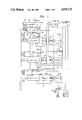
- FIG. 7 is a block diagram of the interior of a node to which the present invention is applied.
- FIG. 8 is a block diagram of a send controller in FIG. 7.
- the number of message buffers to be prepared is calculated from the rates of concentration of messages on nodes lying on a transmission loop, the numbers of messages to be simultaneously processed by devices which are connected to the nodes to actually process the messages, etc., the buffers in that number are disposed, and they are dynamically allotted and shared with a unit being a time till message assembly completion, whereby a buffer capacity can be curtailed.
- the head packet of a message segmented and sent is received, the sender address thereof is registered in the register of an empty buffer, and the data of the packet is written into the buffer. Thenceforth, the data items of packets from the same sender are written into the buffer.
- the buffer When, after receiving the tail packet of the message, the buffer has completed such a process as delivering the message to a host computer, it clears the register so as to be capable of receiving a message from another node.
- FIG. 3 is an architectural diagram of a network system based on a loop transmission method to which the present invention is applied.
- FIG. 3 Shown in FIG. 3 is the network system in which respective nodes 51, 52, 53 and 54 are coupled on a loop by a transmission path 59 and have host computers 55, 56, 57 and 58 connected thereto so as to perform data communications among the computers.
- the present invention is applied to a control circuit within each node.
- the computers communicate with one another through the transfer of messages having desired lengths.
- each of the messages of the desired lengths is segmented into data items of certain fixed length and is endowed with the information items of a destination, a sender, etc., to be changed into the form of packets, with which the communications among the nodes are realized.
- a message from the computer of a sender is transformed into a plurality of packets by the node to which the computer is connected, and the packets are transmitted on the transmission loop and are reassembled into the original message by the mate side node, so that the packets reach the computer of a destination again in the form of the message.
- Frames for carrying the packets are revolving on the transmission loop 59 at a fixed cycle.
- FIG. 4 is a diagram showing a format within the frame.
- numeral 61 designates a synchronous pattern for synchronizing the nodes.
- Numeral 62 designates busy/empty information which indicates whether what is collectively called a "packet field," namely, a field for carrying the packet composed of individual fields 63, 64, 65, 66, 67 and 68 are empty or busy.
- a destination address enters the field 63, and a sender address enter the field 64.
- Control information in the field 65 serves for the indication of the last packet in the case where one message has been decomposed into a plurality of packets, the indication of an effective data length in the data field 66 for expressing a fraction arising when a message of any desired length has been segmented with a fixed length, or the like.
- Data segmented for forming the packet enters the data field 66.
- the field 67 contains frame check sequence information for an error control.
- the loop answer field 68 serves to send a reception situation on a receiving side back to a sender.
- the data field 66 is of fixed length.
- FIG. 5 is a diagram for explaining the segmenting/reassembly of a message
- FIG. 6 is a diagram for explaining the reassembly of a message from packets existing mixedly.
- the segmented packets arrive while coexisting with packets from the other nodes. For this reason, buffers for accumulating the packets from the individual nodes and reassembling them into the original messages have been required in the total number of the nodes in the prior-art system.
- the packets are not always sent uniformly from all the nodes. In a case where the packets of the nodes from specified mates are comparatively large in number, or in a case where the rate of communications is not very high, the buffers prepared in the number of all the nodes are hardly used and are wasteful.
- each node is furnished with a receive mate limiting function (the details of which will be described later with reference to FIG. 1) and a retry sending function (the details of which will be described with reference to FIG. 2), whereby messages are transferred with the required minimum buffer capacity.
- FIG. 7 A detailed block diagram of the node shown in FIG. 3 is depicted in FIG. 7.
- this node it is a receive mate limiter in FIG. 1 that receives packets from the transmission loop and realizes the above operation.
- a retry sending controller shown in FIG. 2 that governs the sending of the packets, especially the retry sending operation. The whole flow shall be stated later, and the central operations of the present invention will be explained here.
- FIG. 1 is a detailed block diagram of the receive mate limiter showing an embodiment of the present invention. It illustrates an example in which the receive mate limiting function mentioned above is realized by circuitry.
- numeral 1 designates a receive data bus being a signal line on which packets having arrived are paralleled in byte unit and flow in succession
- numeral 2 an address comparator which serves to judge if the packet having arrived is from a registered mate
- numeral 3 an address register which stores the address of a mate in order to register the mate as the receive mate
- numeral 4 a flag register which indicates either that the receive mate is registered with a message buffer being in a reservation state or that the receive mate is not registered yet with the message buffer being in an empty state
- numeral 5 the message buffer which stores the data (66 in FIG.
- numeral 6 a gate which serves to indicate that the sender of the packet having arrived is not registered as the mate in any of the buffers
- numeral 7 a selector which selects an empty one of the buffers when the packet not registered has arrived
- numeral 8 a data timing signal which indicates that the data part of the packet is passing on the receive data bus 1
- numeral 9 an SA timing signal which indicates that the sender address (SA) part of the packet is passing on the receive data bus 1
- numeral 10 a timing gate which serves to actuate the comparator 2
- numeral 12 a gate for a write signal into the message buffer
- numeral 13 a latch which holds it till the end of data write into the buffer that the addresses have matched
- numeral 14 a delay circuit which produces a timing for resetting the latch 13 after the turn-off of the data timing signal 8
- numeral 15 a gate which indicates the completion of the message reception
- numeral 16 an end packet pattern which has the same value as a value indicated in the control information (CTL)
- FIG. 2 is a detailed block diagram of the retry sending controller showing another embodiment of the present invention. This embodiment realizes the aforementioned retry sending function in the form of circuitry.
- numeral 31 denotes the loop answer information (LA) from the destination of the first one of a plurality of packets into which a message has been segmented
- numeral 32 an LA receive "not ready" pattern which has the same value as the loop answer information to be returned when the destination node is in an unreceivable state
- numeral 33 a comparator which serves to know whether or not the loop answer indicates that the reception is not ready
- numeral 34 a timer which is started by a match signal from the comparator 33
- numeral 35 a wait time register in which a wait time till the start of retry sending is set beforehand
- numeral 36 a comparator which decides if the timer 34 has reached the preset wait time
- numeral 37 a gate which serves to convey a send request from the host computer or a retry sending request from the comparator 36
- numeral 38 a latch which indicates the send request state
- numeral 39 a gate which serves to deliver a signal for occupying an empty field.
- FIG. 8 shows a send controlling circuit in the prior art. Since this circuit is combined with the retry sending circuit in FIG. 2, it will now be explained.
- numeral 40 denotes a selector for selecting data to be delivered to a send data bus in accordance with any of various timing signals
- numeral 41 the send data bus for sending the packet
- numeral 42 a header information producing circuit which serves to put the destination address, the sender address and an end packet pattern 217 on the packet when the segmented packet is to be sent
- numeral 216 an end packet pattern generator
- numeral 43 a counter for counting the length of data having been delivered at present
- numeral 44 a message length register for storing the length of the message to be sent
- numeral 45 a comparator which decides whether or not the message to be sent has been entirely delivered
- numeral 46 a reader circuit for fetching data to-be-delivered from a message buffer
- numeral 47 the message buffer for storing the message to be delivered.
- the sender address SA
- the empty message buffer 5 to receive the packet is selected by the selector 7, to register the sender address on the receive data bus 1 in the address register 3 of the message buffer and to set busy/empty indicating flag register 4 thereof. Thenceforth, data is gathered in the message buffer 5 at the data timing.
- the selector 7 provides loop answer information (LA information) and gives the sender a reply to the effect that the reception of the sent packet is not ready.
- LA information loop answer information
- the host computer connected to the node In case of the arrival of a packet which is sent from a sender registered in the address register 3 and the control information (CTL information) 18 of which indicates an end pattern, that is, the last packet of a message, the host computer connected to the node is informed of the fact that the reception of the message by the buffer concerned has been completed.
- the buffer When the host computer has read out the message in the buffer, to indicate the end of buffer readout, the buffer has its flag register 4 reset and becomes capable of receiving another message.
- retry sending is performed after a certain time by the retry sending controller shown in FIG. 2. More specifically, when the returned loop answer value (LA value) 31 and the LA receive not-ready pattern 32 compared by the comparator 33 match, the timer 34 is started, and it is waited that the content of the timer is found by the comparator 36 to match with a time previously set in the wait time register 35. After the lapse of the preset time, the retry sending controller operates as if the send request from the host computer were made, and the latch 38 is set by the gate 37, whereby the action of field occupation is started.
- LA value returned loop answer value
- the counter 43 of the send controller being the conventional circuit shown in FIG. 8 and connected to this retry sending controller is reset.
- data in an amount to be afforded by the data timing signal is read out of the message buffer 47 with the header information added thereto, whereby a packet is formed and is sent again.
- communications with any desired mates are permitted using the limited number of message buffers, and besides, the node having sent an unreceived packet is permitted to communicate by sending the packet again after a certain time.
- FIG. 7 is a detailed block diagram of the node shown in FIG. 3.
- the receive mate limiter shown in FIG. 1 and the send controller shown in FIG. 2 as explained before are set up as a receive mate limiter 108 and a send controller 119, and time-divided frames are circulated to switch packets.
- the frame coming from the upper stream of the loop is received from a transmission line 127 into a receiver 101, and serial data is converted into parallel data in byte unit by a shift register 102.
- the pattern of a synchronous pattern generator 103 and the frame converted in byte unit are compared by a comparator 104.
- a timing generation counter 105 is reset, whereby the node and the frame are synchronized.
- various timing signals corresponding to the passing fields of the frame (LA timing 207, CTL timing 214, flag timing 208, SA timing 9, DA timing 213 and data timing 8) are produced from the timing generation counter 105.
- the frame after the conversion in byte unit passes through a selector 114, a flag changer 124 and a selector 126 and is serialized again by a shift register 115, whereupon it is delivered to a transmission line 128 by a sender 116 so as to flow toward the lower stream of the loop.
- the frame data being the output of the shift register 102 and the value of a node address register 106 previously set are compared by a comparator 107 in accordance with the DA timing 213 provided from the timing generation counter 105. In a case where they match, the packet is destined for the own node, and hence, the receive mate limiter 108 is instructed to start the reception operation.
- a frame check sequence checker (FCS check) 129 an FCS calculation is executed to check an error.
- the CTL information is derived from the frame data in accordance with the CTL timing 214, and it is analyzed and delivered to the receive mate limiter 108 by a CTL analyzer 109.
- addresses are compared by the plurality of prepared comparators 2 when it is known from the SA timing 9 that the sender address (SA) has arrived in the packet appearing on the receive data bus 1 shown in FIG. 1.
- Match/mismatch are conveyed from the respective comparators 2 to the gate 6, which gives the selector 7 a result to that effect only when quite no match has been obtained.
- the selector 7 selects the buffer as to which the corresponding one of the flag registers 4 disposed for the respective buffers indicates empty. Assuming here that the channel of message buffer "1" has been selected, the flag register 4 is set, and the "sender address" appearing on the receive data bus 1 is gathered in the address register 3. Thus, a match signal is provided from the comparator 2 to set the latch 13. Thenceforth, since the gate 12 is enabled at the data timing, the data part which corresponds to the single packet appearing on the receive data bus is gathered in the message buffer "1."
- the checked result of the frame check sequence (FCS) checker 129 at the time of reception is put in an LA pattern generator 110.
- an LA pattern to be returned is determined from the checked result and LA information from the receive mate limiter 108, and it is substituted for the older LA from the shift register 102 in the selector 114 at the LA timing.
- the frame is serialized by the shift register 115 and is sent from the sender 116 to the transmission line 128.
- the sender address similarly appears on the receive data bus 1 shown in FIG. 1. Since, however, the same address has already been registered in the address register 3, the match signal is provided from the comparator 2, and the latch 13 is set, so that data is gathered in the message buffer "1" at the data timing.
- the CTL analyzer 109 in FIG. 7 analyzes the CTL information in the packet format and delivers it to the comparator 17 in FIG. 1, included in the receive mate limiter 108.
- the gate 15 gives the host computer ⁇ completion of buffer "1" message processing ⁇ indication via a host computer interface 113 in FIG. 7.
- the host computer reads out the message within the message buffer "1" via the host computer interface 113. Thereafter, when the host computer provides ⁇ end of buffer "1" readout ⁇ indication via the host computer interface 113, the flag register 4 is reset, and the message buffer "1" becomes empty again and usable for another message.
- the host computer prepares a message to-be-sent in a send buffer 120 in FIG. 7 via the host computer interface 113 and sets a send request register 118.
- the send controller 119 gathers the message into the message buffer 47 shown in FIG. 8, included in this send buffer 119, and sets the length thereof in the message length register 44. Since the send request register 118 has been set, the latch 38 is set by the gate 37 so as to start the action of field occupation. More specifically, when an empty detector 117 in FIG. 7 detects the arrival of a frame the ⁇ busy/empty ⁇ indication of which denotes empty, the gate 39 in FIG. 2 is enabled to send a ⁇ flag change occupation ⁇ signal. Upon receiving this signal, the flag changer 124 in FIG. 7 changes the empty indication to the busy indication.
- header information is sent from the header information producing circuit 42 onto the send data bus 41 through the selector 40 in accordance with the DA timing, SA timing and CTL timing.
- the counter 43 is started, while an address is generated by the reader 46, whereby data is read out every byte from the message buffer 47.
- the data is similarly delivered to the send data bus 41 through the selector 40.
- the header information and data delivered are sent to the selector 126 in FIG. 7.
- FCS information is computed by an FCS producing circuit 125 and is also sent to the selector 126.
- the information items are delivered to the transmission line 128 via the shift register 115 as well as the sender 116.
- the quantity of data which can be sent at one time depends upon the size of the packet field on the frame, and the data timing signal with a length corresponding to the size is provided to indicate the quantity. Accordingly, in a case where the message to be sent is longer than the data length of a packet, it is sent from the message buffer 47 in FIG. 8 dividedly a plurality of times. When it is decided by the comparator 45 that a value indicated by the counter 43 has become equal to the value indicated in the message length register 44, the latch 38 is reset to disable the gate 39, and subsequent fields are not occupied.
- the LA value is read out by an LA pattern reader 123, and whether or not it is the LA receive not-ready pattern is checked by the comparator 33 in FIG. 2.
- the LA value is unreceivable, the buffers within the receiving node are regarded as being fully occupied, and the packet is sent again after a certain fixed time. More specifically, the latch 38 is reset by a match signal from the comparator 33 so as to interrupt the sending. In addition, the timer 34 is reset.
- the timer 34 When reset, the timer 34 starts counting from “0.” When the content of the timer has become equal to a value set in the wait time register 35, a match signal is provided from the comparator 36, and the sending controller operates as if the send request were issued from the gate 37 for the first time. Thus, the counter 43 in FIG. 8 is reset, so that the message can be sent from the head thereof. Subsequently, the latch 38 is set, and the resending is started when an empty field has been detected.
- the receive mate limiter is incorporated, and the send controller is additionally endowed with the retry sending function, whereby the limited small number of message buffers for reassembling messages may be prepared in spite of the fact that the buffers must be, in essence, prepared in the number of all the receive mate nodes, and when messages in excess of the prepared buffers have concentrated on any of the nodes, the messages not received are relieved by the operations of the retry sending functions on the sending sides, so that the communications can be maintained.
- the maximum message length which can be handled is becoming 8 Kbytes or so, and the maximum node number of a loop network is usually 128.
- buffers having as large a capacity as 128 nodes ⁇ 8 Kbytes ⁇ 1 Mbyte must be disposed in each of all the nodes for only the purpose of reassembling the messages.
- reductions in size and price are increasingly required of the nodes which are changing from the stationary type to the work station assemblage type, and it is unpractical to install the buffers of such a large capacity merely for the aforementioned purpose.
- the invention can be realized without the necessity for complicatedly controlling the usage of the limited number of buffers.
- the reassembly processing of messages is indispensable to the mini-packet system which is in the limelight as one scheme for realizing the higher speed and larger capacity of the LAN. Therefore, the sharp curtailment of the buffer capacity according to the embodiments is also effective for the realization of ultrahigh-speed LAN in the future.
- each node need not include buffers in the number of all mate nodes, and a limited number of buffers suffice for keeping communications. Therefore, wasteful buffers need not be installed, so that the hardware volume of each node is small to attain economization.
Landscapes
- Engineering & Computer Science (AREA)
- Computer Hardware Design (AREA)
- Physics & Mathematics (AREA)
- Theoretical Computer Science (AREA)
- Mathematical Physics (AREA)
- Software Systems (AREA)
- General Engineering & Computer Science (AREA)
- General Physics & Mathematics (AREA)
- Computer Networks & Wireless Communication (AREA)
- Signal Processing (AREA)
- Small-Scale Networks (AREA)
- Data Exchanges In Wide-Area Networks (AREA)
Abstract
Description
Claims (8)
Applications Claiming Priority (2)
| Application Number | Priority Date | Filing Date | Title |
|---|---|---|---|
| JP62053808A JPH088572B2 (en) | 1987-03-09 | 1987-03-09 | Node device in communication system |
| JP62-53808 | 1987-03-09 |
Publications (1)
| Publication Number | Publication Date |
|---|---|
| US4930122A true US4930122A (en) | 1990-05-29 |
Family
ID=12953091
Family Applications (1)
| Application Number | Title | Priority Date | Filing Date |
|---|---|---|---|
| US07/150,171 Expired - Fee Related US4930122A (en) | 1987-03-09 | 1988-01-29 | Message transfer system and method |
Country Status (4)
| Country | Link |
|---|---|
| US (1) | US4930122A (en) |
| EP (1) | EP0281757B1 (en) |
| JP (1) | JPH088572B2 (en) |
| DE (1) | DE3855739T2 (en) |
Cited By (19)
| Publication number | Priority date | Publication date | Assignee | Title |
|---|---|---|---|---|
| US5023780A (en) * | 1991-01-03 | 1991-06-11 | Northern Telecom Limited | Method of operating a packet switching network |
| US5228027A (en) * | 1990-08-24 | 1993-07-13 | Noboru Yamaguchi | Data communication apparatus |
| US5243596A (en) * | 1992-03-18 | 1993-09-07 | Fischer & Porter Company | Network architecture suitable for multicasting and resource locking |
| US5274637A (en) * | 1989-12-28 | 1993-12-28 | Yamaha Corporation | Token-ring-type local area network |
| US5303347A (en) * | 1991-12-27 | 1994-04-12 | Digital Equipment Corporation | Attribute based multiple data structures in host for network received traffic |
| US5367636A (en) * | 1990-09-24 | 1994-11-22 | Ncube Corporation | Hypercube processor network in which the processor indentification numbers of two processors connected to each other through port number n, vary only in the nth bit |
| US5386415A (en) * | 1990-11-09 | 1995-01-31 | Hitachi, Ltd. | Packet communiction method and packet communication apparatus |
| US5502726A (en) * | 1992-01-31 | 1996-03-26 | Nellcor Incorporated | Serial layered medical network |
| US5502817A (en) * | 1993-04-02 | 1996-03-26 | University Research Foundation, Inc. | Ultra high speed data collection, processing and distribution ring with parallel data paths between nodes |
| US5574931A (en) * | 1993-10-04 | 1996-11-12 | Commissariat A L'energie Atomique | Interconnection process and system for the control of messages in an array of processors having a parallel structure |
| US5761721A (en) * | 1993-12-28 | 1998-06-02 | International Business Machines Corporation | Method and system for cache coherence despite unordered interconnect transport |
| US5878227A (en) * | 1996-07-01 | 1999-03-02 | Sun Microsystems, Inc. | System for performing deadlock free message transfer in cyclic multi-hop digital computer network using a number of buffers based on predetermined diameter |
| US5886982A (en) * | 1993-08-25 | 1999-03-23 | Hitachi, Ltd. | ATM switching system and cell control method |
| US5923657A (en) * | 1994-08-23 | 1999-07-13 | Hitachi, Ltd. | ATM switching system and cell control method |
| US20030051064A1 (en) * | 2001-09-13 | 2003-03-13 | International Business Machines Corporation | Method and system for regulating communication traffic using a limiter thread |
| US6721335B1 (en) * | 1999-11-12 | 2004-04-13 | International Business Machines Corporation | Segment-controlled process in a link switch connected between nodes in a multiple node network for maintaining burst characteristics of segments of messages |
| US6970478B1 (en) * | 1999-06-01 | 2005-11-29 | Nec Corporation | Packet transfer method and apparatus, and packet communication system |
| US6999460B1 (en) * | 2000-10-16 | 2006-02-14 | Storage Technology Corporation | Arbitrated loop port switching |
| US20060174012A1 (en) * | 2005-02-01 | 2006-08-03 | Fujitsu Limited | Relay method, relay apparatus, and computer product |
Families Citing this family (1)
| Publication number | Priority date | Publication date | Assignee | Title |
|---|---|---|---|---|
| US5699520A (en) * | 1994-08-25 | 1997-12-16 | Hewlett-Packard Company | Flow control apparatus and method for a computer interconnect using adaptive credits and flow control tags |
Citations (3)
| Publication number | Priority date | Publication date | Assignee | Title |
|---|---|---|---|---|
| US4665514A (en) * | 1985-08-02 | 1987-05-12 | American Telephone And Telegraph Company, At&T Bell Laboratories | Integrated voice/data network |
| US4736370A (en) * | 1984-12-27 | 1988-04-05 | Fujitsu Limited | Transmitting data processing system |
| US4755986A (en) * | 1985-09-13 | 1988-07-05 | Nec Corporation | Packet switching system |
Family Cites Families (1)
| Publication number | Priority date | Publication date | Assignee | Title |
|---|---|---|---|---|
| US4742511A (en) * | 1985-06-13 | 1988-05-03 | Texas Instruments Incorporated | Method and apparatus for routing packets in a multinode computer interconnect network |
-
1987
- 1987-03-09 JP JP62053808A patent/JPH088572B2/en not_active Expired - Fee Related
-
1988
- 1988-01-29 US US07/150,171 patent/US4930122A/en not_active Expired - Fee Related
- 1988-02-02 EP EP88101485A patent/EP0281757B1/en not_active Expired - Lifetime
- 1988-02-02 DE DE3855739T patent/DE3855739T2/en not_active Expired - Fee Related
Patent Citations (3)
| Publication number | Priority date | Publication date | Assignee | Title |
|---|---|---|---|---|
| US4736370A (en) * | 1984-12-27 | 1988-04-05 | Fujitsu Limited | Transmitting data processing system |
| US4665514A (en) * | 1985-08-02 | 1987-05-12 | American Telephone And Telegraph Company, At&T Bell Laboratories | Integrated voice/data network |
| US4755986A (en) * | 1985-09-13 | 1988-07-05 | Nec Corporation | Packet switching system |
Non-Patent Citations (4)
| Title |
|---|
| "Data Transmission", (Nippon Telegraph and Telephone Corporation), pp. 354-367. |
| "Packet Switching Technology and Application", (pp. 88-92, (1982), edited by the Japan Institute of Electronics, Information and Communication Engineers. |
| Data Transmission , (Nippon Telegraph and Telephone Corporation), pp. 354 367. * |
| Packet Switching Technology and Application , (pp. 88 92, (1982), edited by the Japan Institute of Electronics, Information and Communication Engineers. * |
Cited By (31)
| Publication number | Priority date | Publication date | Assignee | Title |
|---|---|---|---|---|
| US5274637A (en) * | 1989-12-28 | 1993-12-28 | Yamaha Corporation | Token-ring-type local area network |
| US5228027A (en) * | 1990-08-24 | 1993-07-13 | Noboru Yamaguchi | Data communication apparatus |
| US5367636A (en) * | 1990-09-24 | 1994-11-22 | Ncube Corporation | Hypercube processor network in which the processor indentification numbers of two processors connected to each other through port number n, vary only in the nth bit |
| US5386415A (en) * | 1990-11-09 | 1995-01-31 | Hitachi, Ltd. | Packet communiction method and packet communication apparatus |
| US5467346A (en) * | 1990-11-09 | 1995-11-14 | Hitachi, Ltd. | Packet communication method and packet communication apparatus |
| US5023780A (en) * | 1991-01-03 | 1991-06-11 | Northern Telecom Limited | Method of operating a packet switching network |
| US5303347A (en) * | 1991-12-27 | 1994-04-12 | Digital Equipment Corporation | Attribute based multiple data structures in host for network received traffic |
| US5502726A (en) * | 1992-01-31 | 1996-03-26 | Nellcor Incorporated | Serial layered medical network |
| US5243596A (en) * | 1992-03-18 | 1993-09-07 | Fischer & Porter Company | Network architecture suitable for multicasting and resource locking |
| US5841974A (en) * | 1993-04-02 | 1998-11-24 | University Research Foundation, Inc. | Ultra high speed data collection, processing and distriubtion ring with parallel data paths between nodes |
| US5502817A (en) * | 1993-04-02 | 1996-03-26 | University Research Foundation, Inc. | Ultra high speed data collection, processing and distribution ring with parallel data paths between nodes |
| US5886982A (en) * | 1993-08-25 | 1999-03-23 | Hitachi, Ltd. | ATM switching system and cell control method |
| US6021130A (en) * | 1993-08-25 | 2000-02-01 | Hitachi, Ltd. | ATM switching system and cell control method |
| US6252877B1 (en) | 1993-08-25 | 2001-06-26 | Hitachi, Ltd. | ATM switching system and cell control method |
| US6389026B1 (en) | 1993-08-25 | 2002-05-14 | Hitachi, Ltd. | ATM switching system and cell control method |
| US7095726B2 (en) | 1993-08-25 | 2006-08-22 | Hitachi, Ltd. | ATM switching system and cell control method |
| US5574931A (en) * | 1993-10-04 | 1996-11-12 | Commissariat A L'energie Atomique | Interconnection process and system for the control of messages in an array of processors having a parallel structure |
| US5761721A (en) * | 1993-12-28 | 1998-06-02 | International Business Machines Corporation | Method and system for cache coherence despite unordered interconnect transport |
| US6088768A (en) * | 1993-12-28 | 2000-07-11 | International Business Machines Corporation | Method and system for maintaining cache coherence in a multiprocessor-multicache environment having unordered communication |
| US5923657A (en) * | 1994-08-23 | 1999-07-13 | Hitachi, Ltd. | ATM switching system and cell control method |
| US5878227A (en) * | 1996-07-01 | 1999-03-02 | Sun Microsystems, Inc. | System for performing deadlock free message transfer in cyclic multi-hop digital computer network using a number of buffers based on predetermined diameter |
| USRE38650E1 (en) * | 1996-07-01 | 2004-11-09 | Sun Microsystems, Inc. | System for performing deadlock free message transfer in cyclic multi-hop digital computer network using a number of buffers based on predetermined diameter |
| US6970478B1 (en) * | 1999-06-01 | 2005-11-29 | Nec Corporation | Packet transfer method and apparatus, and packet communication system |
| US6721335B1 (en) * | 1999-11-12 | 2004-04-13 | International Business Machines Corporation | Segment-controlled process in a link switch connected between nodes in a multiple node network for maintaining burst characteristics of segments of messages |
| US6999460B1 (en) * | 2000-10-16 | 2006-02-14 | Storage Technology Corporation | Arbitrated loop port switching |
| US20030051064A1 (en) * | 2001-09-13 | 2003-03-13 | International Business Machines Corporation | Method and system for regulating communication traffic using a limiter thread |
| US7299470B2 (en) * | 2001-09-13 | 2007-11-20 | International Business Machines Corporation | Method and system for regulating communication traffic using a limiter thread |
| US20080022289A1 (en) * | 2001-09-13 | 2008-01-24 | Curtis Bryce A | Method and system for regulating communication traffic using a limiter thread |
| US8001545B2 (en) | 2001-09-13 | 2011-08-16 | International Business Machines Corporation | Method and system for regulating communication traffic using a limiter thread |
| US20060174012A1 (en) * | 2005-02-01 | 2006-08-03 | Fujitsu Limited | Relay method, relay apparatus, and computer product |
| US8326916B2 (en) * | 2005-02-01 | 2012-12-04 | Fujitsu Limited | Relay method, relay apparatus, and computer product |
Also Published As
| Publication number | Publication date |
|---|---|
| JPS63220631A (en) | 1988-09-13 |
| JPH088572B2 (en) | 1996-01-29 |
| EP0281757A3 (en) | 1991-10-09 |
| EP0281757A2 (en) | 1988-09-14 |
| DE3855739D1 (en) | 1997-02-20 |
| DE3855739T2 (en) | 1997-07-31 |
| EP0281757B1 (en) | 1997-01-08 |
Similar Documents
| Publication | Publication Date | Title |
|---|---|---|
| US4930122A (en) | Message transfer system and method | |
| US4549291A (en) | Hybrid local communication network, operating both in circuit and packet modes | |
| US5495482A (en) | Packet transmission system and method utilizing both a data bus and dedicated control lines | |
| EP0076880B1 (en) | A local area contention network data communication system | |
| US4768190A (en) | Packet switching network | |
| CA1193692A (en) | Collision avoiding system and protocol for a two path multiple access digital communications system | |
| US4566097A (en) | Token ring with secondary transmit opportunities | |
| EP0054077B1 (en) | Method of transmitting information between stations attached to a unidirectional transmission ring | |
| US4644533A (en) | Packet switch trunk circuit queueing arrangement | |
| EP0308449B1 (en) | Transfer of messages in a multiplexed system | |
| US5477541A (en) | Addressing technique for storing and referencing packet data | |
| EP0129581B1 (en) | Method and apparatus for graceful preemption on a digital communications link | |
| US4962498A (en) | Multi-length packet format including check sequence(s) | |
| US4586175A (en) | Method for operating a packet bus for transmission of asynchronous and pseudo-synchronous signals | |
| EP0100662A2 (en) | Digital communication system | |
| EP0448494A2 (en) | Method of controlling access to a bus in a distributed queue dual bus (DQDB) network | |
| US5740373A (en) | Packet switching system having communication control unit for sending acknowledgment to the source upon receiving the receive response data associated with the last cell | |
| WO1983000412A1 (en) | Idle time slot seizure and transmission facilities for loop communication system | |
| US4901313A (en) | A-point to multi-points communication system | |
| US6490264B1 (en) | Data transmission method and system | |
| WO1987001545A1 (en) | Packet switched local network with priority random splitting and conflict detection | |
| US5001706A (en) | Packet cross connect switch system including improved throughput | |
| WO2002001785A1 (en) | Media access control for isochronous data packets in carrier sensing multiple access systems | |
| US5168496A (en) | System for internetwork communication between local areas networks | |
| KR100259082B1 (en) | Method for determining priority in network traffic |
Legal Events
| Date | Code | Title | Description |
|---|---|---|---|
| AS | Assignment |
Owner name: HITACHI, LTD., 6, KANDA SURUGADAI 4-CHOME, CHIYODA Free format text: ASSIGNMENT OF ASSIGNORS INTEREST.;ASSIGNORS:TAKAHASHI, YASUHIRO;TAKADA, OSAMU;REEL/FRAME:004839/0671 Effective date: 19871228 Owner name: HITACHI, LTD., A CORP. OF JAPAN,JAPAN Free format text: ASSIGNMENT OF ASSIGNORS INTEREST;ASSIGNORS:TAKAHASHI, YASUHIRO;TAKADA, OSAMU;REEL/FRAME:004839/0671 Effective date: 19871228 Owner name: HITACHI, LTD., JAPAN Free format text: ASSIGNMENT OF ASSIGNORS INTEREST;ASSIGNORS:TAKAHASHI, YASUHIRO;TAKADA, OSAMU;REEL/FRAME:004839/0671 Effective date: 19871228 |
|
| FEPP | Fee payment procedure |
Free format text: PAYOR NUMBER ASSIGNED (ORIGINAL EVENT CODE: ASPN); ENTITY STATUS OF PATENT OWNER: LARGE ENTITY |
|
| FPAY | Fee payment |
Year of fee payment: 4 |
|
| FPAY | Fee payment |
Year of fee payment: 8 |
|
| REMI | Maintenance fee reminder mailed | ||
| LAPS | Lapse for failure to pay maintenance fees | ||
| STCH | Information on status: patent discontinuation |
Free format text: PATENT EXPIRED DUE TO NONPAYMENT OF MAINTENANCE FEES UNDER 37 CFR 1.362 |
|
| FP | Lapsed due to failure to pay maintenance fee |
Effective date: 20020529 |