US4932675A - Skate assembly - Google Patents
Skate assembly Download PDFInfo
- Publication number
- US4932675A US4932675A US07/219,504 US21950488A US4932675A US 4932675 A US4932675 A US 4932675A US 21950488 A US21950488 A US 21950488A US 4932675 A US4932675 A US 4932675A
- Authority
- US
- United States
- Prior art keywords
- grooves
- portions
- upper portion
- tongues
- attachment
- Prior art date
- Legal status (The legal status is an assumption and is not a legal conclusion. Google has not performed a legal analysis and makes no representation as to the accuracy of the status listed.)
- Expired - Lifetime
Links
Images


Classifications
-
- A—HUMAN NECESSITIES
- A63—SPORTS; GAMES; AMUSEMENTS
- A63C—SKATES; SKIS; ROLLER SKATES; DESIGN OR LAYOUT OF COURTS, RINKS OR THE LIKE
- A63C1/00—Skates
- A63C1/22—Skates with special foot-plates of the boot
-
- A—HUMAN NECESSITIES
- A63—SPORTS; GAMES; AMUSEMENTS
- A63C—SKATES; SKIS; ROLLER SKATES; DESIGN OR LAYOUT OF COURTS, RINKS OR THE LIKE
- A63C1/00—Skates
- A63C1/04—Skates fastened by means of clamps
- A63C1/08—Skates fastened by means of clamps with simultaneously-tightened sole and heel clamps
-
- A—HUMAN NECESSITIES
- A63—SPORTS; GAMES; AMUSEMENTS
- A63C—SKATES; SKIS; ROLLER SKATES; DESIGN OR LAYOUT OF COURTS, RINKS OR THE LIKE
- A63C17/00—Roller skates; Skate-boards
- A63C17/18—Roller skates; Skate-boards convertible into ice or snow-running skates
Definitions
- the present invention relates to skate assemblies having sub assemblies including ice blades or rollers, which sub assemblies are attached to skating boots by attachment means that allow users to easily remove attached sub assemblies from the boots and then re-attach the same or different compatible sub assemblies to the boots.
- the present invention provides a skate assembly including a sub assembly that may include a blade or rollers and can be attached to a boot by attachment means that allow the sub assembly to be relatively easily removed from the boot by the user to afford changing sub assemblies and thereby, for example, changing a sharp blade for a dull blade, interchanging blades between left and right boots to change dull inner edges for sharper outer edges, or to change blades for rollers if it is desired to skate over a different surface; which assembly is light, can have a conventional appearing structure, and includes mean for releasably attaching the sub assembly to a boot that effectively prevents relative movement between the sub assembly and the boot, including during prolonged hard use of the skate assembly such as by a serious skater playing hockey in the amateur or professional leagues.
- a skate assembly comprising front and rear attachment portions adapted to be incorporated in or attached respectively to the sole and heel of a boot.
- the skate assembly also includes an elongate sub-assembly including a molded polymeric frame having a lower portion in which is mounted means (e.g., an ice blade or in line rollers) projecting past a bottom surface of the lower portion for affording rapid movement of the skate assembly along a substrate (e.g., an ice sheet or paved surface respectively), and spaced front and rear upper portions each having opposite spaced side wall portions projecting away from the lower portion.
- Means are provided for releasably engaging the rear upper portion to the rear attachment portion and the front upper portion to the front attachment portion.
- one of the portions has surfaces defining a pair of grooves extending along its side surfaces from inlets adjacent one of its ends toward the other of its ends; and the other of the portions has a pair of tongues extending from one of its ends toward the other of its ends, with each tongue projecting from a different one of its side surfaces and adapted to enter a different one of the grooves from the inlet to an engaged position with the surfaces of the tongues in frictional engagement with the surfaces defining the grooves; and fastening means are provided to releasably retain the portions with the tongues in the grooves in the engaged position.
- the attachment portion can provide the tongues and recesses along the upper surfaces of the tongues; and the upper portion of the frame can have ridges defining the upper surfaces of the grooves that are positioned in the recesses when the pair of portions are engaged.
- the tongues can project in opposite directions generally parallel to an upper surface of the attachment portion and the grooves are recessed from the inner surfaces of the side walls forming the upper portions of the frame.
- the tongues can be opposed and project toward each other generally parallel to that upper surface, and the grooves can be recessed from the outer surfaces of the side walls forming the upper portions of the frame.
- the tongues can enter the grooves from inlets either at the front or the rear of the upper portion of the frame, with entry from inlets at the front being preferred so that impacts against the front of the frame during skating will not tend to dislodge the tongues from the grooves.
- the opposite inner surfaces and/or the upper and lower surfaces that define the grooves can be tapered from the inlets to the grooves and the tongues can have surfaces correspondingly tapered and adapted to fully engage the inner and/or upper and lower surfaces defining the grooves when the tongues are fully engaged in the grooves.
- the opposite upper and lower surfaces partially defining the grooves and along the tongues can be disposed to form dovetail transverse cross sections for the grooves and tongues to thereby further restrict relative movement therebetween, including any tendency for the tongues to move transversally out of the grooves.
- the fastening means can comprise, for one pair of portions to be engaged, a first fastening member attached to one of the portions and a second fastening member engaging the other of the portions and adapted to releasably engage the first fastening member.
- the first fastening member can be attached to the rear upper portion adjacent its front end and extend longitudinally of the sub-assembly toward the rear end of the rear upper portion
- the rear attachment portion can have a part projecting along the rear end of the rear upper portion when the tongues are engaged in the grooves.
- the second fastener member can be positioned within the projecting part at which position it may easily be manipulated through the rear end of the rear attachment member (e.g., with some type of wrench) to releasably engage the second fastener member (which may be an internally threaded nut) with the first fastener member (which may have a threaded end portion for engagement by the nut).
- the rear attachment member can have a projecting part projecting along the front end of the rear upper portion when the tongues are engaged in the grooves
- the first fastening member e.g., an internally threaded insert
- the second fastening member e.g., an allen head bolt
- the projecting parts can be received in a socket in the rear upper portion when the tongues are fully received in the grooves to retain a smooth conventional contoured shape for the rear upper portion.
- the shape of the attaching portions used on right and let boots are preferably the same so that the sub assemblies can be interchanged between left and right boots to, for example, change dull inner edges on ice blades (which typically become dull more quickly during skating) for sharper outer edges, to thereby improve skating performance without again sharpening the blades and thereby increase the usable life of the blades.
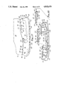
- FIGS. 1, 2, and 3 are side views of a first embodiment of a skate assembly according to the present invention illustrated with attachment portions of the skate assembly attached to a boot and sequentially illustrating movement of a sub-assembly of the skate assembly from a disengaged to an engaged position with resepect to the attachment portions;
- FIG. 4 is a perspective view of the skate assembly and boot illustrated in FIG. 1 with the portions and sub-assembly in the disengaged position;
- FIG. 5 is a side view of the sub-assembly illustrated in FIG. 1;
- FIG. 6 is a top view of the sub-assembly illustrated in FIG. 1;
- FIG. 7 is a vertical front end view of the sub-assembly of the skate assembly illustrated in FIG. 1;
- FIG. 8 is a fragmentary vertical section view of the skate assembly and boot illustrated in FIG. 1 with the attachment portions and sub-assembly in the engaged position illustrated in FIG. 3;
- FIGS. 9, 10, 11, and 12 are sectional views taken approximately along lines 9--9, 10--10, 11--11, and 12--12 of FIG. 1 respectively;
- FIG. 13 is a vertical front end view of a rear attachment portion included in the skate assembly illustrate in FIG. 1;
- FIG. 14 is a sectional view taken approximately along line 14--14 of FIG. 1;
- FIG. 15 is a vertical front end view of front attachment portion included in the skate assembly illustrated in FIG. 1;
- FIG. 16 is a side view of a second embodiment of a skate assembly according to the present invention.
- FIG. 17 is a side view of a third embodiment of a skate assembly according to the present invention shown attached to a boot;
- FIG. 18 is vertical sectional view of a sub assembly included in the skate assembly of FIG. 1 together with vertical side views of front and rear attachment portions of that skate assembly separated from the sub assembly;
- FIG. 19 is a top view of the sub assembly in the skate assembly of FIG. 16;
- FIG. 20 is a sectional view taken approximately along line 20--20 of FIG. 19;
- FIG. 21 is a sectional view taken approximately along line 21--21 of FIG. 19;
- FIG. 22 is a rear end view of the sub assembly as illustrated in FIG. 19;
- FIG. 23 is a bottom view of the front attachment portion shown separated in FIG. 18;
- FIG. 24 is a front view of the front attachment portion shown separated in FIG. 18;
- FIG. 25 is a rear view of the front attachment portion shown separated in FIG. 18;
- FIG. 26 is a bottom view of the rear attachment portion shown separated in FIG. 18;
- FIG. 27 is a front view of the rear attachment portion shown separated in FIG. 18;
- FIG. 28 is a rear view of the rear attachment portion shown separated in FIG. 18.
- FIG. 29 is a side view of a forth embodiment of a skate assembly according to the present invention.
- FIGS. 1-15 a first embodiment of a skate assembly according to the present invention generally designated by the reference numeral 10.
- the skate assembly 10 is a hockey type skated assembly and comprises front and rear attachment portions 12 and 13 having generally planar upper or top surfaces 14 and 15, front ends 16 and 17, rear ends 18 and 19, and opposite side surfaces extending between the front and rear ends 16 and 18 or 17 and 19.
- the front and rear attachment portions 12 and 13 are adapted to be attached respectively to the sole and heel of a boot 20 as illustrated with their upper surfaces 14 and 15 against the bottom surfaces on the sole and heel and the front ends 16 and 17 of the attachment portions 12 and 13 adjacent a front end 21 of the boot 20.
- the skate assembly also includes an elongate sub-assembly 24 including a molded polymeric (e.g., nylon or urethane) frame 26 having a front end 27, a rear end 28, a lower portion 29 having a bottom surface 30 from which downwardly projects means in the form of an ice blade 31 for affording rapid movement of the skate assembly 10 along a substrate such as a sheet of ice, and spaced front and rear upper portions 32 and 33.
- a molded polymeric (e.g., nylon or urethane) frame 26 having a front end 27, a rear end 28, a lower portion 29 having a bottom surface 30 from which downwardly projects means in the form of an ice blade 31 for affording rapid movement of the skate assembly 10 along a substrate such as a sheet of ice, and spaced front and rear upper portions 32 and 33.
- a molded polymeric (e.g., nylon or urethane) frame 26 having a front end 27, a rear end 28, a lower portion 29 having a bottom surface 30 from which
- Each of the upper portions 32 and 33 includes a wall with an outer surface and an inner surface defining a central cavity opening through its upper or uppermost surface 34 or 35, which wall has opposite spaced side wall portions 36 or 37, projects upwardly away from the lower portion 29, and has front ends adjacent the front end 27 of the frame 26 and rear ends adjacent the rear end 28 of the frame 26.
- Attachment means are provided for releasably engaging the rear upper portion 33 of the frame 26 to the rear attachment portion 13 and the front upper portion 32 of the frame 26 to the front attachment portion 12.
- the spaced side wall portions 37 of the rear upper portion 33 of the frame 26 have opposite grooves 38 along their outer surfaces, which grooves 38 are defined by opposite upper and lower surfaces and innermost or recessed surfaces and extend generally parallel to its upper surface 35 from an inlet 39 adjacent its front end toward its rear end; and the rear attachment portion 13 has a pair of opposed inwardly projecting tongues 42 having opposite upper and lower surfaces and opposed innermost or distal surfaces extending from the rear end toward the front end of the rear attachment portion 13 into a central opening in the rear attachment portion 13.
- the tongues 42 are adapted to enter different ones of the grooves 38 endwise from their inlets 39 and now generally parallel to the upper surfaces 34 and 35 of the upper portions 32 and 33 to an engaged position (FIGS. 3 and 8) with the surfaces on the tongues 42 and the surfaces defining the grooves 38 in close surface to surface engagement.
- the rear attachment portion 13 has recesses 44 along the upper surfaces of the tongues 42; and the rear upper portion 33 of the frame 26 has ridges 45 defining the upper surfaces of the grooves 38, which ridges 45 are positioned in the recesses 44 when the rear attachment portion 13 and the rear upper portion 33 of the frame 26 are engaged.
- the spaced side wall portions 36 of the front upper portion 32 of the frame 26 have opposite grooves 46 along their outer surfaces, which grooves 46 are defined by opposite upper and lower surfaces and innermost surfaces, extend generally parallel to the upper surface 14 of the front upper portion 32 from an inlet 48 adjacent its front end toward its rear end; and the front attachment portion 12 has a pair of opposed inwardly projecting tongues 49 having upper and lower surfaces and opposed innermost surfaces extending from the rear end toward the front end of the front attachment portion 12 into a central opening in the front attachment portion 12 so that from the disengaged position of the attachment portions 12 and 13 and upper portions 32 and 33 (FIGS.
- the tongues 49 are adapted to enter a different one of the grooves 46 from their inlets 48 and move generally parallel to the upper surfaces 14 and 15 of the upper portions 32 and 33 to an engaged position (FIGS. 3 and 8) with the surfaces on the tongues 49 and the surfaces defining the grooves in close surface to surface engagement.
- the front attachment portion 12 has recesses 52 along the upper surfaces of the tongues 49; and the front upper portion 32 of the frame 26 has ridges 53 defining the upper surfaces of the grooves 46, which ridges 53 are positioned in the recesses 52 when the front attachment portion 12 and the front upper portion 32 of the frame 26 are engaged.
- the opposite inner surfaces that define the grooves 38 and 46 are tapered outwardly from the inlets 39 and 48 to the grooves 38 and 46, and the opposed innermost surfaces of the tongues 42 and 49 are correspondingly tapered outwardly away from the front ends 16 and 17 of the attachment portions 12 and 13 at the same angle so that they will fully and frictionally engage the inner surfaces defining the grooves 38 and 46 when the tongues 42 and 49 are fully engaged in the grooves 38 and 46.
- the upper surfaces defining the grooves 38 and 46 can be parallel to the upper surfaces 34 and 35 or can be tapered by a slight angle c as illustrated in FIG. 5 with respect to the upper surfaces 34 and 35 of the upper portions 32 and 33 and the upper surfaces of the tongues can be correspondingly tapered so that when the tongues 42 and 49 are fully engaged in the grooves 38 and 46 the upper surfaces of the tongues 42 and 49 will also frictionally engage the upper surfaces defining the grooves 38 and 46 that are along the ridges 45 and 53 at right angles to the inner surfaces of the grooves 38 and 46.
- the outer surfaces of the ridges 45 and 53 may also be tapered away from the inlet ends of the grooves 38 and 46 (such as at angles A and B with respect to the longitudinale center line of the sub assembly 24 as illustrated in FIG. 6), and the inner surfaces of the recesses may be correspondingly tapered so that they will fully and frictionally engage the outer surfaces of the ridges 45 and 53 when the tongues 42 and 49 are fully engaged in the grooves 38 and 46.
- Fastening means are provided to releasably retain the attachment portions 12 and 13 and the upper portions 32 and 33 in the engaged position.
- the rear attachment portion 13 has a projecting part 56 projecting along the front end of the rear upper portion 33 when the tongues 42 and 49 are engaged in the grooves 38 and 46.
- a first fastening member or internally threaded insert 57 is attached to the projecting part 56, and a second fastening member or allen headed bolt 58 extends through openings in the rear upper portion 33 longitudinally of the sub-assembly 24 toward the front end of the rear upper portion 33 and had a threaded end portion adapted to releasably engage the threaded insert 57.
- the blade 31 is mounted in the frame 26 by having an upper portion of the blade 31 received in a close fitting groove opening through its bottom surface 30, and is held in the groove by upwardly projectly bolts with nuts 59 at their upper ends in and accessible through the cavaties in the upper portions 32 and 33 of the frame 26.
- FIG. 16 there is shown a second embodiment of a skate assembly 60 according to the present invention which include front and rear attachment portions 61 and 62 attached to a boot 63 and a sub assembly 64 including a frame 65 having front and rear upper portions 66 and 67 that releasably engage the attachment portions 61 and 62 in the same manner that the upper portions 32 and 33 of the frame 26 engage the attachment portions 12 and 13 in the skate assembly 10 described above, and which portions 61, 62, 66 and 67 are also held in their engaged position by similar attaching means including a bolt 68.
- the skate assembly 60 primarily differs from the skate assembly 10 in that the means for affording rapid movement of the skate assembly 60 along a substrate is a plurality of aligned wheels 69 rotatably mounted by parallel transverse axle bolts 70 between spaced longitudinal parts of a lower portion 71 of the frame 65 with portions of the wheels 69 projecting from its lower surface to afford movement of the skate assembly 64 along a substrate such as a paved street.
- FIGS. 17 through 28 a third embodiment of a skate assembly according to the present invention generally designated by the reference numeral 80.
- the skate assembly 80 is a hockey type skate assembly comprising front and rear attachment portions 82 and 83 having respectively generally planar upper or top surfaces 84 and 85, front ends 86 and 87, rear ends 88 and 89, and opposite side surfaces extending between the front and rear ends 86 and 88 or 87 and 89.
- the front and rear attachment portions 82 and 83 as illustrated are adapted to be attached respectively to the sole and heel of a boot 90 by rivets through holes 92 around their peripheries with their upper surfaces 84 and 85 against the bottom surfaces on the sole and heel and the front ends 86 and 87 of the attachment portions 82 and 83 adjacent a front end 91 of the boot 90.
- the skate assembly also includes an elongate sub-assembly 94 including a molded polymeric (e.g., nylon or urethane) frame 96 having a front end 97, a rear end 98, a lower portion 99 having a bottom surface 100 from which downwardly projects means in the form of an ice blade 101 for affording rapid movement of the skate assembly 80 along a substrate such as a sheet of ice, and spaced front and rear upper portions 102 and 103.
- a molded polymeric (e.g., nylon or urethane) frame 96 having a front end 97, a rear end 98, a lower portion 99 having a bottom surface 100 from which downwardly projects means in the form of an ice blade 101 for affording rapid movement of the skate assembly 80 along a substrate such as a sheet of ice, and spaced front and rear upper portions 102 and 103.
- a molded polymeric (e.g., nylon or urethane) frame 96 having a front end 97,
- Each of the upper portions 102 and 103 includes a wall with an outer surface and an inner surface defining a central cavity opening through its upper or uppermost surface 104 or 105, which wall has spaced side wall portions 106 or 107, projects and diverges upwardly from the lower portion 96, and has front ends adjacent the front end 97 of the frame 96 and rear ends adjacent the rear end 98 of the frame 96.
- Attachment means are included in the skate assembly 80 for releasably engaging the rear upper portion 103 of the frame 96 to the rear attachment portion 83 and the front upper portion 102 of the frame 96 to the front attachment portion 82.
- the rear upper portion 103 of the frame 96 has a pair of opposed grooves 108 along the inner surfaces of its spaced side wall portions 107, each defined by opposite upper and lower surfaces and innermost or recessed surfaces, which grooves 108 extend generally parallel to its upper surface 105 from an inlet 109 adjacent its rear end toward its front end; and the rear attachment portion 83 has a pair of opposite outwardly projecting tongues 112 having opposite upper and lower surfaces and outermost or distal surfaces extending from the front end toward the rear end of the rear attachment portion 83.
- the tongues 112 are adapted to enter different ones of the grooves 108 endwise from their inlets 109 and move generally parallel to the upper surfaces 104 and 105 of the upper portions 102 and 103 to an engaged position (FIG. 17) with the surfaces on the tongues 112 and the surfaces defining the grooves 108 in close surface to surface engagement.
- the rear attachment portion 83 comprises a top plate part having the upper surface 85, an opposite lower surface, and a peripheral edge surface 113 between the upper and lower surfaces extending beyond all portions of the tongues 112, and has recesses 114 along the upper surfaces of the tongues 112; and the rear upper portion 103 of the frame 96 has ridges 115 defining the upper surfaces of the grooves 108, which ridges 115 are positioned in the recesses 114 when the rear attachment portion 83 and rear upper portion 103 of the frame 96 are engaged.
- the front upper portion 102 of the frame 96 has a pair of opposed grooves 116 along the inner surfaces of the spaced side wall portions 106 each defined by opposite upper and lower surfaces and innermost surfaces, which grooves 116 extend generally parallel to its upper surface 104 from an inlet 118 adjacent its rear end toward its front end; and the front attachment portion 82 has a pair of opposite outwardly projecting tongues 119 having opposite upper and lower surfaces and outmost surfaces extending from the front end 86 toward the rear end 88 of the front attachment portion 82. From the disengaged position of the attachment portions 82 and 83 and upper portions 102 and 103 (FIG.
- the tongues 119 are adapted to enter a different one of the grooves 116 from their inlets 118 and move generally parallel to the upper surfaces 104 and 105 of the upper portions 102 and 103 to an engaged position (FIG. 17) at which the surfaces on the tongues 119 and the surfaces defining the grooves 116 are in surface to surface engagement.
- Thr front attachment portion 82 comprises a top plate part having the upper surface 84, an opposite lower surface, and a pheripheral edge surface 120 between the upper and lower surfaces extending beyond all portions of the tongues 119, and the attachment portion has recesses 122 along the upper surfaces of the tongues 119; and the front upper portion 102 of the frame 96 has ridges 123 defining the upper surfaces of the grooves 116, which ridges 123 are positioned in the recesses 122 when the front attachment portion 82 and the front upper portion 102 of the frame 96 are engaged.
- the opposite upper and lower surfaces defining the grooves 108 and 116 are tapered toward each other from the inlets 109 and 118 at a slight angle (e.g., 1 degree for each surface) and the tongues 112 and 119 have surfaces similarly tapered and adapted to fully engage the upper and lower surfaces when the tongues 112 and 119 are fully engaged in the grooves 108 and 116. Also, the opposite upper and lower surfaces defining the grooves 108 and 116 and on the tongues 112 and 119 are disposed to form dovetail transverse cross sections for the grooves 108 and 116 and the tongues 112 and 119.
- Fastening means are provided to releasably retain the attachment portions 82 and 83 and the upper portions 102 and 103 in the engaged position.
- a square head 125 on one end of a first fastening member or bolt 126 is attached to the rear upper portion 103 adjacent its front end with the bolt 126 extending longitudinally of the sub-assembly 94 toward the rear end of the rear upper portion 103, and the bolt 126 has a threaded end portion opposite its head 125.
- the rear attachment portion 83 has a projecting part 128 projecting along the rear end of the rear upper portion 103 when the tongues 112, 115 are in the in the grooves 108 and 116.
- a second fastener member or internally threaded nut 130 is rotatably mounted in a socket in the projecting part 128 when the sub-assembly 94 is engaged with the attachment portions 82 and 83 the projecting end of the bolt 126 will be received in a longitudinal bore 131 between the tongues 112 in the rear attachment portion 83 aligned with the nut 130 and rotation of the nut 130 using a tool or spanner wrench engaged with it will cause the nut 130 to engage the threaded end of the bolt 126 and draw the sub assembly 94 toward it until the projecting part 128 is positioned in a correspondly shaped socket along the rear end of the rear upper portion 103 (which engagement is along surfaces transverse to the sub assembly 94 and further restricts relative movement between the rear upper portion 103 and the rear attachment portion 83) and the tongues 112 and 119 are in full surface to surface frictional engagement with the grooves 108 and 116.
- the tightened nut 130 will then hold the tongues 112 and 119 and grooves 108 and 116 in such engagement while the skate assembly is used, but can be subsequently released by reverse rotation of the nut 130 bolt to allow separation of the sub assembly 94 from the attachment portions 82 and 83, which separation will typically require a sharp blow to the sub assembly 94 to release the frictional engagement between the tongues 112 and 119 and the surfaces defining the grooves 108 and 116.
- the blade 101 has an upper longitudinal portion with spaced upwardly projecting and diverging tabs 132 with through transverse openings and has generally triangular through transverse openings 133 in upwardly projecting portions adjacent its ends.
- the lower portion 99 of the frame 96 is molded around the upper longitudinal portion of the blade 101 and extends around and through the openings in the tabs 132 and through the triangular openings 133 to help hold the blade 101 in place.
- the blade 101 also has a series of evenly spaced, longitudinal through transverse openings 134 along the bottom surface 100 of the frame 96 which both lighten the blade 101 and are decorative.
- FIG. 29 there is shown a forth embodiment of a skate assembly 160 according to the present invention which includes front and rear attachment portions 161 and 162 adapted to be attached to a boot and a sub assembly 164 including a frame 165 having front and rear upper portions 166 and 167 that releasably engage the attachment portions 161 and 162 in the same manner that the upper portions 102 and 103 of the frame 96 engage the attachment portions 82 and 83 in the skate assembly 80 described above, and which portions 161, 162, 166 and 167 are also held in their engaged position by similar attaching means.
- the skate assembly 160 primarily differs from the skate assembly 80 in that the means for affording rapid movement of the skate assembly 160 along a substrate is a plurality of aligned wheels 169 rotatably mounted by parallel transverse axles 170 between spaced longitudinally extrending parts of a lower portion 171 of the frame 165 with portions of the wheels 169 projecting from its lower surface to afford movement of the skate assembly 160 along a substrate such as a paved street.
- the present invention has now been described with reference to four embodiments thereof. It will be apparent to those skilled in the art that many changes can be made in the embodiments described without departing from the scope of the present invention.
- the front and attachment portions could be molded as portions of the soles and heels of skating boots, thereby avoiding the necessity to rivet them in place.
- Various other attachment means could be used to releasably retain the attachment portions and the upper portions in the engaged position, and such attachment means could be between the front upper portion and front attachment portion.
- the scope of the present invention should not be limited to the structure described in this application, but only by structure described by the language of the claims and the equivalents of those structures.
Abstract
Description
Claims (41)
Priority Applications (7)
| Application Number | Priority Date | Filing Date | Title |
|---|---|---|---|
| US07/219,504 US4932675A (en) | 1986-11-28 | 1988-07-15 | Skate assembly |
| JP1508524A JPH04500918A (en) | 1988-07-15 | 1989-07-12 | skate assembly |
| EP89909089A EP0428584B1 (en) | 1988-07-15 | 1989-07-12 | Skate assembly |
| AU40450/89A AU4045089A (en) | 1988-07-15 | 1989-07-12 | Skate assembly |
| DE68922106T DE68922106D1 (en) | 1988-07-15 | 1989-07-12 | ICE SKATE STRUCTURE. |
| PCT/US1989/003011 WO1990000425A1 (en) | 1988-07-15 | 1989-07-12 | Skate assembly |
| CA000605900A CA1325819C (en) | 1988-07-15 | 1989-07-17 | Skate assembly |
Applications Claiming Priority (2)
| Application Number | Priority Date | Filing Date | Title |
|---|---|---|---|
| US93577186A | 1986-11-28 | 1986-11-28 | |
| US07/219,504 US4932675A (en) | 1986-11-28 | 1988-07-15 | Skate assembly |
Related Parent Applications (1)
| Application Number | Title | Priority Date | Filing Date |
|---|---|---|---|
| US93577186A Continuation-In-Part | 1986-11-28 | 1986-11-28 |
Publications (1)
| Publication Number | Publication Date |
|---|---|
| US4932675A true US4932675A (en) | 1990-06-12 |
Family
ID=22819540
Family Applications (1)
| Application Number | Title | Priority Date | Filing Date |
|---|---|---|---|
| US07/219,504 Expired - Lifetime US4932675A (en) | 1986-11-28 | 1988-07-15 | Skate assembly |
Country Status (7)
| Country | Link |
|---|---|
| US (1) | US4932675A (en) |
| EP (1) | EP0428584B1 (en) |
| JP (1) | JPH04500918A (en) |
| AU (1) | AU4045089A (en) |
| CA (1) | CA1325819C (en) |
| DE (1) | DE68922106D1 (en) |
| WO (1) | WO1990000425A1 (en) |
Cited By (52)
| Publication number | Priority date | Publication date | Assignee | Title |
|---|---|---|---|---|
| US5088749A (en) * | 1989-11-10 | 1992-02-18 | Icaro Olivieri & C. S.P.A. Minuterie | Ice skate with interchangeable skid blade |
| US5137290A (en) * | 1991-07-08 | 1992-08-11 | Iowa State University Research Foundation, Inc. | Ice skate blade alignment mechanism |
| US5193827A (en) * | 1992-04-14 | 1993-03-16 | O.S. Designs, Inc. | Convertible in-line roller skates |
| US5248156A (en) * | 1991-02-15 | 1993-09-28 | Cann Brian G | Ice skate blade assembly having a removeable runner |
| US5314199A (en) * | 1992-04-14 | 1994-05-24 | O.S. Designs, Inc. | Convertible in-line roller skates |
| US5320366A (en) * | 1993-03-05 | 1994-06-14 | Lawrence Shing | Assembly for converting inline roller skate to ice skate |
| US5332242A (en) * | 1989-02-24 | 1994-07-26 | Cann Brian G | Ice skate blade assembly and removable runner for same |
| US5390752A (en) * | 1993-03-31 | 1995-02-21 | Scarab Manufacturing And Leasing, Inc. | Drive train suspension system |
| US5393077A (en) * | 1993-03-01 | 1995-02-28 | Wanous; Craig C. | All season skate |
| US5411278A (en) * | 1991-07-31 | 1995-05-02 | Koflach Sport Gesellschaft M.B.H. & Co. Kg. | Skating shoe |
| US5437466A (en) * | 1993-07-19 | 1995-08-01 | K-2 Corporation | In-line roller skate |
| US5524912A (en) * | 1993-03-01 | 1996-06-11 | Laub; Michael J. | All season skate |
| US5549310A (en) * | 1993-07-19 | 1996-08-27 | K-2 Corporation | In-line roller skate with improved frame assembly |
| US5580070A (en) * | 1994-10-21 | 1996-12-03 | All American Aviation & Mfg. Inc. | Adjustable skate truck assembly |
| WO1997016228A1 (en) * | 1995-11-01 | 1997-05-09 | Motiv Sports, Inc. | In-line roller or ice skate with adjustable chassis |
| US5641169A (en) * | 1994-10-21 | 1997-06-24 | Bekessy; George J. | Quick release ice skate blade assembly |
| US5662338A (en) * | 1995-02-15 | 1997-09-02 | Victor Posa | Skate with lateral torque support members |
| US5803466A (en) * | 1997-01-09 | 1998-09-08 | Rike Industries, Inc. | Toe plate with dual flanges for in-line skate frame |
| US5820138A (en) * | 1996-04-30 | 1998-10-13 | Hajat Dost Sani; Bigan | Convertible in-line roller skates |
| US5836592A (en) * | 1997-01-17 | 1998-11-17 | Chang; Sheng-Hsiung | Structure for in-line roller skates |
| US5839734A (en) * | 1994-12-30 | 1998-11-24 | Victor Posa | Convertible skate |
| US5873584A (en) * | 1995-01-17 | 1999-02-23 | Rike Inline, Inc. | In-line roller skate frame |
| FR2772627A1 (en) | 1997-12-23 | 1999-06-25 | Salomon Sa | SYSTEM FOR QUICK CONNECTION OF A SHOE TO A SPORTS ARTICLE |
| US5915703A (en) * | 1997-01-09 | 1999-06-29 | Rike Industries, Inc. | In-line skate axle and related assembly method |
| US5961129A (en) * | 1997-02-07 | 1999-10-05 | Post; Peter G. | Quick-Release interlocking frame assembly for interchangeably mounting operative sports devices to a boot sole |
| US6015156A (en) * | 1998-06-11 | 2000-01-18 | Seneca Sports, Inc. | Skate with detachable boot |
| US6042125A (en) * | 1998-02-10 | 2000-03-28 | Wu; Elbert Hsin En | Inline skate with detachable roller device |
| US6098997A (en) * | 1998-07-30 | 2000-08-08 | Cheng; Tsan-Hsiung | In-line roller skate with two-piece frame for wheels |
| US6105975A (en) * | 1998-01-30 | 2000-08-22 | Nike, Inc. | Skate blade holding system |
| US6135463A (en) * | 1997-01-09 | 2000-10-24 | Rike Industries, Inc. | In-line skate with quick release sidewalls and related assembly methods |
| US6142489A (en) * | 1997-11-26 | 2000-11-07 | Salomon S.A. | Support and wear element for an in-line roller skate frame |
| US6213479B1 (en) | 1998-06-02 | 2001-04-10 | Jimmy Cochimin | Convertible in-line/parallel skates |
| US6322088B1 (en) | 1998-06-09 | 2001-11-27 | Mattel, Inc. | Convertible skate |
| US6422577B2 (en) | 1998-11-24 | 2002-07-23 | K-2 Corporation | Foam core in-line skate frame |
| US6425587B1 (en) | 2000-08-29 | 2002-07-30 | Aaron G. Moon | Multi-functional roller skates |
| US6446984B2 (en) | 1998-11-24 | 2002-09-10 | K-2 Corporation | Foam core skate frame with embedded insert |
| US6460864B1 (en) * | 2001-05-18 | 2002-10-08 | Gary Shieh | Shoe with detachable sporting device |
| US6481724B1 (en) | 2000-04-14 | 2002-11-19 | Renny Carl Whipp | Adapter for converting in-line roller skates to ice skates |
| US6485033B2 (en) * | 1997-07-15 | 2002-11-26 | Bauer Italia S.P.A. | Ice skate with interchangeable blades |
| US20030155724A1 (en) * | 2002-02-20 | 2003-08-21 | Chen-Wen Wang | Locking device for a detachable skate of sport shoe |
| US6698768B2 (en) * | 2002-01-04 | 2004-03-02 | Chang Chun-Cheng | Sports shoe having a detachable ice/roller skate |
| US20040090023A1 (en) * | 2002-08-27 | 2004-05-13 | Crowder Troy Stacey | Adjustable hockey skate blade system |
| US6851681B2 (en) | 1998-11-24 | 2005-02-08 | K-2 Corporation | Skate frame with cap construction |
| US20080150242A1 (en) * | 2005-01-31 | 2008-06-26 | Holger Wurthner | Skating Sports Device with a Detachably Mounted Exchangeable Blade |
| US20100242308A1 (en) * | 2009-03-31 | 2010-09-30 | Belles Gordon L | Footwear with interface for attaching devices |
| US20120056390A1 (en) * | 2009-03-02 | 2012-03-08 | Tecnica Group S.P.A. | Skate |
| US20130093150A1 (en) * | 2011-10-18 | 2013-04-18 | Earl Arthur Dahlo | Double-edged skate blade assembly and holder |
| US8544854B2 (en) * | 2011-12-09 | 2013-10-01 | Roger R. Adams | Wearable device with attachment system |
| US8544855B2 (en) | 2012-01-10 | 2013-10-01 | Robbie Shepley | Skate with interchangeable use elements |
| US8641054B2 (en) | 2010-07-16 | 2014-02-04 | Roger R. Adams | Wearable device |
| US20160242496A1 (en) * | 2015-02-20 | 2016-08-25 | Kelly Barnes | Article of footwear |
| US9756897B1 (en) * | 2015-08-27 | 2017-09-12 | Alan Millis | Skating warm up system |
Families Citing this family (10)
| Publication number | Priority date | Publication date | Assignee | Title |
|---|---|---|---|---|
| WO1993007938A1 (en) * | 1991-10-25 | 1993-04-29 | Forthuber Guenter | Connector system for single or multiple row skating devices |
| US5331752A (en) * | 1992-01-14 | 1994-07-26 | Rollerblade, Inc. | Skate with detachable shoe |
| US5318310A (en) * | 1992-08-27 | 1994-06-07 | Sport Maska Inc. | Runner support for a skate |
| DE4444315A1 (en) * | 1994-12-13 | 1996-06-27 | Samy Dipl Ing Kamal | Safety roller skates with interchangeable base |
| DE29613982U1 (en) * | 1996-08-13 | 1997-03-13 | Nawrath Harald | Shoes with removable roll holder |
| DE19637301A1 (en) * | 1996-09-13 | 1998-03-19 | Stephan Kaiser | Multifunction boot for roller-skates, ice skates etc. |
| FR2810249B1 (en) * | 2000-06-19 | 2002-10-25 | Roger Ours | ICE SKATE, AND ASSEMBLY FOR SUCH A SKATE |
| USRE44422E1 (en) | 2002-04-26 | 2013-08-13 | Bauer Hockey, Inc. | Ice skate blade |
| USD488846S1 (en) | 2002-04-26 | 2004-04-20 | Bauer Nike Hockey, Inc. | Ice skate blade |
| US8297627B2 (en) | 2004-02-03 | 2012-10-30 | Smith Ii George T | Skate with an accessible runner securing system and methods thereof |
Citations (14)
| Publication number | Priority date | Publication date | Assignee | Title |
|---|---|---|---|---|
| DE20215C (en) * | GEBR. EHRENTRAUT in Berlin W., Potsdamerstrafse 63 | Skate attachment | ||
| US908536A (en) * | 1908-04-13 | 1909-01-05 | Otto Arlund | Skate. |
| US2706119A (en) * | 1950-05-27 | 1955-04-12 | Ralph E Uphoff | Skate and shoe construction |
| US2868553A (en) * | 1957-03-14 | 1959-01-13 | Rieckman Werner | Combination ice and roller skates |
| US3026118A (en) * | 1959-09-03 | 1962-03-20 | Pare Victor | Skate and shoe combination |
| US3367669A (en) * | 1965-10-18 | 1968-02-06 | Exemplary Entpr Ltd | Convertible skate |
| US4008901A (en) * | 1975-06-11 | 1977-02-22 | Conn J L | Triple skate attachments |
| US4108450A (en) * | 1976-04-28 | 1978-08-22 | Bernard Cote | Roller skate |
| US4114295A (en) * | 1977-05-05 | 1978-09-19 | Schaefer Hans Joachim | Convertible sports shoe |
| US4218069A (en) * | 1978-07-26 | 1980-08-19 | Tuuk Sports Ltd. | Ice skate and method of manufacture therefor |
| US4351536A (en) * | 1980-08-15 | 1982-09-28 | Sandino Hector M | Ice skate attachment |
| US4492385A (en) * | 1982-07-21 | 1985-01-08 | Olson Scott B | Skate having an adjustable blade or wheel assembly |
| US4549742A (en) * | 1980-05-05 | 1985-10-29 | Koh-I-Noor Bilovec, Norodni Podnik | Ice skate |
| US4657265A (en) * | 1985-12-13 | 1987-04-14 | Ruth Paul M | Convertible skate |
Family Cites Families (3)
| Publication number | Priority date | Publication date | Assignee | Title |
|---|---|---|---|---|
| US2118892A (en) * | 1936-11-11 | 1938-05-31 | Mays Earle Walten | Skating footwear |
| US2998260A (en) * | 1960-01-26 | 1961-08-29 | Meyer Paul | Combined shoe and interchangeable skates |
| CA984422A (en) * | 1974-05-07 | 1976-02-24 | Kenbudge Holdings Limited | Ice skate |
-
1988
- 1988-07-15 US US07/219,504 patent/US4932675A/en not_active Expired - Lifetime
-
1989
- 1989-07-12 JP JP1508524A patent/JPH04500918A/en active Pending
- 1989-07-12 DE DE68922106T patent/DE68922106D1/en not_active Expired - Lifetime
- 1989-07-12 AU AU40450/89A patent/AU4045089A/en not_active Abandoned
- 1989-07-12 EP EP89909089A patent/EP0428584B1/en not_active Expired - Lifetime
- 1989-07-12 WO PCT/US1989/003011 patent/WO1990000425A1/en active IP Right Grant
- 1989-07-17 CA CA000605900A patent/CA1325819C/en not_active Expired - Fee Related
Patent Citations (14)
| Publication number | Priority date | Publication date | Assignee | Title |
|---|---|---|---|---|
| DE20215C (en) * | GEBR. EHRENTRAUT in Berlin W., Potsdamerstrafse 63 | Skate attachment | ||
| US908536A (en) * | 1908-04-13 | 1909-01-05 | Otto Arlund | Skate. |
| US2706119A (en) * | 1950-05-27 | 1955-04-12 | Ralph E Uphoff | Skate and shoe construction |
| US2868553A (en) * | 1957-03-14 | 1959-01-13 | Rieckman Werner | Combination ice and roller skates |
| US3026118A (en) * | 1959-09-03 | 1962-03-20 | Pare Victor | Skate and shoe combination |
| US3367669A (en) * | 1965-10-18 | 1968-02-06 | Exemplary Entpr Ltd | Convertible skate |
| US4008901A (en) * | 1975-06-11 | 1977-02-22 | Conn J L | Triple skate attachments |
| US4108450A (en) * | 1976-04-28 | 1978-08-22 | Bernard Cote | Roller skate |
| US4114295A (en) * | 1977-05-05 | 1978-09-19 | Schaefer Hans Joachim | Convertible sports shoe |
| US4218069A (en) * | 1978-07-26 | 1980-08-19 | Tuuk Sports Ltd. | Ice skate and method of manufacture therefor |
| US4549742A (en) * | 1980-05-05 | 1985-10-29 | Koh-I-Noor Bilovec, Norodni Podnik | Ice skate |
| US4351536A (en) * | 1980-08-15 | 1982-09-28 | Sandino Hector M | Ice skate attachment |
| US4492385A (en) * | 1982-07-21 | 1985-01-08 | Olson Scott B | Skate having an adjustable blade or wheel assembly |
| US4657265A (en) * | 1985-12-13 | 1987-04-14 | Ruth Paul M | Convertible skate |
Cited By (83)
| Publication number | Priority date | Publication date | Assignee | Title |
|---|---|---|---|---|
| US5332242A (en) * | 1989-02-24 | 1994-07-26 | Cann Brian G | Ice skate blade assembly and removable runner for same |
| US5383674A (en) * | 1989-02-24 | 1995-01-24 | Cann; Brian G. | Ice skate blade assembly and removeable runner for same |
| US5088749A (en) * | 1989-11-10 | 1992-02-18 | Icaro Olivieri & C. S.P.A. Minuterie | Ice skate with interchangeable skid blade |
| US5248156A (en) * | 1991-02-15 | 1993-09-28 | Cann Brian G | Ice skate blade assembly having a removeable runner |
| US5137290A (en) * | 1991-07-08 | 1992-08-11 | Iowa State University Research Foundation, Inc. | Ice skate blade alignment mechanism |
| US5411278A (en) * | 1991-07-31 | 1995-05-02 | Koflach Sport Gesellschaft M.B.H. & Co. Kg. | Skating shoe |
| US5193827A (en) * | 1992-04-14 | 1993-03-16 | O.S. Designs, Inc. | Convertible in-line roller skates |
| US5314199A (en) * | 1992-04-14 | 1994-05-24 | O.S. Designs, Inc. | Convertible in-line roller skates |
| US5524912A (en) * | 1993-03-01 | 1996-06-11 | Laub; Michael J. | All season skate |
| US5393077A (en) * | 1993-03-01 | 1995-02-28 | Wanous; Craig C. | All season skate |
| US5320366A (en) * | 1993-03-05 | 1994-06-14 | Lawrence Shing | Assembly for converting inline roller skate to ice skate |
| US5390752A (en) * | 1993-03-31 | 1995-02-21 | Scarab Manufacturing And Leasing, Inc. | Drive train suspension system |
| US20040207164A1 (en) * | 1993-07-19 | 2004-10-21 | K-2 Corporation | In-line roller skate |
| US5848796A (en) * | 1993-07-19 | 1998-12-15 | K-2 Corporation | In-line roller skate |
| US5549310A (en) * | 1993-07-19 | 1996-08-27 | K-2 Corporation | In-line roller skate with improved frame assembly |
| US6139030A (en) * | 1993-07-19 | 2000-10-31 | K-2 Corporation | In-line roller skate |
| US6254110B1 (en) | 1993-07-19 | 2001-07-03 | K-2 Corporation | In-line roller skate |
| US6367818B2 (en) | 1993-07-19 | 2002-04-09 | K-2 Corporation | In-line roller skate |
| US6152459A (en) * | 1993-07-19 | 2000-11-28 | K-2 Corporation | In-line roller skate |
| US5452907A (en) * | 1993-07-19 | 1995-09-26 | K-2 Corporation | Skate with adjustable base and frame |
| US5437466A (en) * | 1993-07-19 | 1995-08-01 | K-2 Corporation | In-line roller skate |
| US6749203B2 (en) | 1993-07-19 | 2004-06-15 | K-2 Corporation | In-line roller skate |
| US6598888B2 (en) | 1993-07-19 | 2003-07-29 | K-2 Corporation | In-line roller skate |
| US5580070A (en) * | 1994-10-21 | 1996-12-03 | All American Aviation & Mfg. Inc. | Adjustable skate truck assembly |
| US5641169A (en) * | 1994-10-21 | 1997-06-24 | Bekessy; George J. | Quick release ice skate blade assembly |
| US6065758A (en) * | 1994-12-30 | 2000-05-23 | Victor Posa | Skate |
| US5845927A (en) * | 1994-12-30 | 1998-12-08 | Victor Posa | Convertible skate |
| US5839734A (en) * | 1994-12-30 | 1998-11-24 | Victor Posa | Convertible skate |
| US5873584A (en) * | 1995-01-17 | 1999-02-23 | Rike Inline, Inc. | In-line roller skate frame |
| US5662338A (en) * | 1995-02-15 | 1997-09-02 | Victor Posa | Skate with lateral torque support members |
| US5810368A (en) * | 1995-02-15 | 1998-09-22 | Victor Posa | Skate with lateral toroque support members |
| WO1997016228A1 (en) * | 1995-11-01 | 1997-05-09 | Motiv Sports, Inc. | In-line roller or ice skate with adjustable chassis |
| US5820138A (en) * | 1996-04-30 | 1998-10-13 | Hajat Dost Sani; Bigan | Convertible in-line roller skates |
| US6045143A (en) * | 1997-01-09 | 2000-04-04 | Rike Industries, Inc. | Toe plate with dual flanges for in-line skate frame |
| US6082746A (en) * | 1997-01-09 | 2000-07-04 | Rike Industries, Inc. | In-line skate axle and related assembly method |
| US5803466A (en) * | 1997-01-09 | 1998-09-08 | Rike Industries, Inc. | Toe plate with dual flanges for in-line skate frame |
| US6135463A (en) * | 1997-01-09 | 2000-10-24 | Rike Industries, Inc. | In-line skate with quick release sidewalls and related assembly methods |
| US5915703A (en) * | 1997-01-09 | 1999-06-29 | Rike Industries, Inc. | In-line skate axle and related assembly method |
| US5836592A (en) * | 1997-01-17 | 1998-11-17 | Chang; Sheng-Hsiung | Structure for in-line roller skates |
| US5961129A (en) * | 1997-02-07 | 1999-10-05 | Post; Peter G. | Quick-Release interlocking frame assembly for interchangeably mounting operative sports devices to a boot sole |
| US6485033B2 (en) * | 1997-07-15 | 2002-11-26 | Bauer Italia S.P.A. | Ice skate with interchangeable blades |
| US6142489A (en) * | 1997-11-26 | 2000-11-07 | Salomon S.A. | Support and wear element for an in-line roller skate frame |
| US6270089B1 (en) | 1997-12-23 | 2001-08-07 | Salomon S.A. | System for rapidly linking a boot to a sport article and a skate incorporating such system |
| EP0925812A1 (en) | 1997-12-23 | 1999-06-30 | Salomon S.A. | Quick acting coupling between a shoe to a sportarticle |
| FR2772627A1 (en) | 1997-12-23 | 1999-06-25 | Salomon Sa | SYSTEM FOR QUICK CONNECTION OF A SHOE TO A SPORTS ARTICLE |
| US6105975A (en) * | 1998-01-30 | 2000-08-22 | Nike, Inc. | Skate blade holding system |
| US6042125A (en) * | 1998-02-10 | 2000-03-28 | Wu; Elbert Hsin En | Inline skate with detachable roller device |
| US6213479B1 (en) | 1998-06-02 | 2001-04-10 | Jimmy Cochimin | Convertible in-line/parallel skates |
| US6322088B1 (en) | 1998-06-09 | 2001-11-27 | Mattel, Inc. | Convertible skate |
| US6015156A (en) * | 1998-06-11 | 2000-01-18 | Seneca Sports, Inc. | Skate with detachable boot |
| US6098997A (en) * | 1998-07-30 | 2000-08-08 | Cheng; Tsan-Hsiung | In-line roller skate with two-piece frame for wheels |
| US6422577B2 (en) | 1998-11-24 | 2002-07-23 | K-2 Corporation | Foam core in-line skate frame |
| US6446984B2 (en) | 1998-11-24 | 2002-09-10 | K-2 Corporation | Foam core skate frame with embedded insert |
| US7214337B2 (en) | 1998-11-24 | 2007-05-08 | K-2 Corporation | Foam core in-line skate frame |
| US20050161892A1 (en) * | 1998-11-24 | 2005-07-28 | K-2 Corporation | Skate frame with cap construction |
| US6648344B2 (en) | 1998-11-24 | 2003-11-18 | K-2 Corporation | Foam core in-line skate frame |
| US6851681B2 (en) | 1998-11-24 | 2005-02-08 | K-2 Corporation | Skate frame with cap construction |
| US20040113314A1 (en) * | 1998-11-24 | 2004-06-17 | K-2 Corporation | Foam core in-line skate frame |
| US6481724B1 (en) | 2000-04-14 | 2002-11-19 | Renny Carl Whipp | Adapter for converting in-line roller skates to ice skates |
| US6425587B1 (en) | 2000-08-29 | 2002-07-30 | Aaron G. Moon | Multi-functional roller skates |
| US6460864B1 (en) * | 2001-05-18 | 2002-10-08 | Gary Shieh | Shoe with detachable sporting device |
| US6698768B2 (en) * | 2002-01-04 | 2004-03-02 | Chang Chun-Cheng | Sports shoe having a detachable ice/roller skate |
| US6736411B2 (en) * | 2002-02-20 | 2004-05-18 | Chen-Wen Wang | Locking device for a detachable skate of sport shoe |
| US20030155724A1 (en) * | 2002-02-20 | 2003-08-21 | Chen-Wen Wang | Locking device for a detachable skate of sport shoe |
| US20040090023A1 (en) * | 2002-08-27 | 2004-05-13 | Crowder Troy Stacey | Adjustable hockey skate blade system |
| US7673884B2 (en) * | 2005-01-31 | 2010-03-09 | Onyx-Systems Patentmanagement Gmbh | Skating sports device with a detachably mounted exchangeable blade |
| US20080150242A1 (en) * | 2005-01-31 | 2008-06-26 | Holger Wurthner | Skating Sports Device with a Detachably Mounted Exchangeable Blade |
| US20120056390A1 (en) * | 2009-03-02 | 2012-03-08 | Tecnica Group S.P.A. | Skate |
| US8746707B2 (en) * | 2009-03-02 | 2014-06-10 | Tecnica Group S.P.A. | Skate |
| US20100242308A1 (en) * | 2009-03-31 | 2010-09-30 | Belles Gordon L | Footwear with interface for attaching devices |
| US11511181B2 (en) | 2010-07-16 | 2022-11-29 | V.N.O. Llc | Wearable device |
| US9901809B2 (en) | 2010-07-16 | 2018-02-27 | V.N.O. Llc | Wearable device |
| US9492732B2 (en) | 2010-07-16 | 2016-11-15 | Roger R. Adams | Wearable device |
| US8641054B2 (en) | 2010-07-16 | 2014-02-04 | Roger R. Adams | Wearable device |
| US8690165B2 (en) | 2010-07-16 | 2014-04-08 | Roger R. Adams | Wearable device |
| US8801002B2 (en) | 2010-07-16 | 2014-08-12 | Roger R. Adams | Wearable device |
| US8882114B2 (en) | 2010-07-16 | 2014-11-11 | Roger R. Adams | Wearable device |
| US9433851B2 (en) * | 2011-10-18 | 2016-09-06 | Switchblade Sports (Bc) Corp. | Double-edged skate blade assembly and holder |
| US20130093150A1 (en) * | 2011-10-18 | 2013-04-18 | Earl Arthur Dahlo | Double-edged skate blade assembly and holder |
| US8544854B2 (en) * | 2011-12-09 | 2013-10-01 | Roger R. Adams | Wearable device with attachment system |
| US8544855B2 (en) | 2012-01-10 | 2013-10-01 | Robbie Shepley | Skate with interchangeable use elements |
| US20160242496A1 (en) * | 2015-02-20 | 2016-08-25 | Kelly Barnes | Article of footwear |
| US9756897B1 (en) * | 2015-08-27 | 2017-09-12 | Alan Millis | Skating warm up system |
Also Published As
| Publication number | Publication date |
|---|---|
| WO1990000425A1 (en) | 1990-01-25 |
| EP0428584A4 (en) | 1991-12-04 |
| AU4045089A (en) | 1990-02-05 |
| DE68922106D1 (en) | 1995-05-11 |
| CA1325819C (en) | 1994-01-04 |
| EP0428584B1 (en) | 1995-04-05 |
| EP0428584A1 (en) | 1991-05-29 |
| JPH04500918A (en) | 1992-02-20 |
Similar Documents
| Publication | Publication Date | Title |
|---|---|---|
| US4932675A (en) | Skate assembly | |
| US5810368A (en) | Skate with lateral toroque support members | |
| US4107857A (en) | Athletic shoe construction | |
| US5277437A (en) | Skate apparatus | |
| US5027904A (en) | Racing plate horseshoe system with movable calks | |
| US6623017B1 (en) | Skate with removable blade | |
| US5320366A (en) | Assembly for converting inline roller skate to ice skate | |
| US20020190487A1 (en) | Goalie skate protective shell with removable blade | |
| JPH07209A (en) | Hard plate of spike shoes for athletic sports | |
| US9433851B2 (en) | Double-edged skate blade assembly and holder | |
| US6065758A (en) | Skate | |
| US4241929A (en) | Ski board with improved foot treads | |
| US5735536A (en) | Skate and skate chassis and method of making and using the same | |
| US4373736A (en) | Two wheel roller skate | |
| US20100225100A1 (en) | Skating and boarding system having a mounting adapter and interchangeable components | |
| US6173975B1 (en) | V-line skate with expandable axle | |
| US6422578B1 (en) | In-line skate with auxiliary wheel, auxiliary wheel and method | |
| US4379563A (en) | Auxiliary ice skate blade | |
| US2631861A (en) | Roller skate attachment | |
| US6217035B1 (en) | Skate | |
| US3403461A (en) | Football cleat | |
| US20220151344A1 (en) | Spike and key system and method | |
| US3367669A (en) | Convertible skate | |
| EP0877644B1 (en) | In-line skate frame | |
| US20090184481A1 (en) | Unitary quad roller skate |
Legal Events
| Date | Code | Title | Description |
|---|---|---|---|
| AS | Assignment |
Owner name: OLSON, SCOTT B., 10357 MORGAN AVENUE SOUTH, BLOOMI Free format text: ASSIGNMENT OF ASSIGNORS INTEREST.;ASSIGNORS:MC NAMARA, GEORGE E.;HENNESSY, JOSEPH J.;REEL/FRAME:004965/0451 Effective date: 19881014 Owner name: OLSON, SCOTT B., MINNESOTA Free format text: ASSIGNMENT OF ASSIGNORS INTEREST;ASSIGNORS:MC NAMARA, GEORGE E.;HENNESSY, JOSEPH J.;REEL/FRAME:004965/0451 Effective date: 19881014 |
|
| STCF | Information on status: patent grant |
Free format text: PATENTED CASE |
|
| FEPP | Fee payment procedure |
Free format text: PAT HLDR NO LONGER CLAIMS SMALL ENT STAT AS INDIV INVENTOR (ORIGINAL EVENT CODE: LSM1); ENTITY STATUS OF PATENT OWNER: SMALL ENTITY |
|
| AS | Assignment |
Owner name: INNOVATIVE SPORT SYSTEMS, INCORPORATED, MINNESOTA Free format text: ASSIGNMENT OF ASSIGNORS INTEREST.;ASSIGNOR:OLSON, SCOTT B.;REEL/FRAME:006375/0783 Effective date: 19930105 |
|
| FPAY | Fee payment |
Year of fee payment: 4 |
|
| AS | Assignment |
Owner name: TIMM, GERALD W., MINNESOTA Free format text: ASSIGNMENT OF ASSIGNORS INTEREST;ASSIGNOR:INNOVATIVE SPORT SYSTEMS, INC.;REEL/FRAME:006817/0616 Effective date: 19930922 |
|
| FEPP | Fee payment procedure |
Free format text: PAT HOLDER CLAIMS SMALL ENTITY STATUS - SMALL BUSINESS (ORIGINAL EVENT CODE: SM02); ENTITY STATUS OF PATENT OWNER: SMALL ENTITY |
|
| FPAY | Fee payment |
Year of fee payment: 8 |
|
| FPAY | Fee payment |
Year of fee payment: 12 |