US4934685A - Sheet feeder for two stacks of sheets - Google Patents
Sheet feeder for two stacks of sheets Download PDFInfo
- Publication number
- US4934685A US4934685A US06/737,960 US73796085A US4934685A US 4934685 A US4934685 A US 4934685A US 73796085 A US73796085 A US 73796085A US 4934685 A US4934685 A US 4934685A
- Authority
- US
- United States
- Prior art keywords
- stack
- sheets
- tray
- sheet
- roller
- Prior art date
- Legal status (The legal status is an assumption and is not a legal conclusion. Google has not performed a legal analysis and makes no representation as to the accuracy of the status listed.)
- Expired - Fee Related
Links
Images

Classifications
-
- G—PHYSICS
- G03—PHOTOGRAPHY; CINEMATOGRAPHY; ANALOGOUS TECHNIQUES USING WAVES OTHER THAN OPTICAL WAVES; ELECTROGRAPHY; HOLOGRAPHY
- G03G—ELECTROGRAPHY; ELECTROPHOTOGRAPHY; MAGNETOGRAPHY
- G03G15/00—Apparatus for electrographic processes using a charge pattern
- G03G15/65—Apparatus which relate to the handling of copy material
- G03G15/6502—Supplying of sheet copy material; Cassettes therefor
-
- B—PERFORMING OPERATIONS; TRANSPORTING
- B65—CONVEYING; PACKING; STORING; HANDLING THIN OR FILAMENTARY MATERIAL
- B65H—HANDLING THIN OR FILAMENTARY MATERIAL, e.g. SHEETS, WEBS, CABLES
- B65H1/00—Supports or magazines for piles from which articles are to be separated
- B65H1/30—Supports or magazines for piles from which articles are to be separated with means for replenishing the pile during continuous separation of articles therefrom
Definitions
- Feeders of this type have been used, for example, for feeding document sheets in an electrographic copier seriatim from a tray to a station where the sheets are illuminated for copying.
- the sheets in the stack represent a job to be copied.
- the operator wishes to copy another stack of sheets comprising a second job, the operator waits until all sheets of the first stack have been fed from the tray before the tray is loaded with the second stack of sheets.
- Another object of the invention is to provide a sheet feeder capable of maintaining separation of different jobs in the apparatus, and to such a feeder which allows a second job to be automatically fed after the first job without operator intervention.
- a sheet feeder for feeding sheets seriatim from first and second stacks of sheets supported by a tray. Initially the first stack of sheets rests on the tray and the second stack of sheets is on top of the first stack.
- the feeder includes a sheet feed member engageable with the bottom sheet in the tray for advancing the sheets seriatim from the tray along a sheet path.
- a stack separation roller is located above the tray and is mounted for movement toward and away from the tray. The separation roller is engageable with the top sheet in the first stack of sheets and is engageable by an edge of the second stack to offset such edge of the second stack from a corresponding edge of the first stack.
- the separation roller and the second stack move downwardly toward the tray as sheets are fed from the first stack by the sheet feed member.
- the separation roller is raised after the top sheet of the first stack has been fed from the tray. This permits the second stack of sheets to be fed seriatim along the sheet path by the sheet feed member.
- FIG. 1 is a plan view of a preferred embodiment of a sheet feeder of the present invention
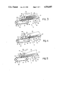
- FIG. 2 is a cross section view through the feeder of FIG. 1 and showing two stacks of sheets in the feeder;
- FIG. 3 is a detail view illustrating operation of the feed assist rollers
- FIG. 4 is fragmentary view, similar to part of FIG. 2, but showing the feeder after the first stack of sheets has been removed from the tray;
- FIG. 5 is a view similar to FIG. 4 but illustrating the second stack of sheets in position for feeding.
- a preferred embodiment of a sheet feeder of the present invention is generally designated 10 and, as illustrated in the drawings, can be used for feeding document sheets to a station 12 of an electrographic copier.
- the sheets are illuminated and an image thereof is provided to a photoconductor of the copier for making copies in a manner known in the art.
- Feeder 10 includes a tray generally designated 14 having a substantially flat bottom plate 16 for supporting a first stack of document sheets 18 comprising a first job to be run on the copier and a second stack of document sheets 20 comprising a second job to be run on the copier.
- the stacks of document sheets are preferably centered along a centerline 22 (FIG. 1) of the feeder.
- the document sheets can be located with respect to centerline 22 by a pair of adjustable side guides 24, 26 located at opposite side edge portions of the tray.
- the guides 24, 26 are substantially parallel to the centerline 22 and equally spaced from the centerline.
- the side guides are coupled for conjoint movement toward and away from the centerline in any suitable manner.
- indicia can be provided on the upper surface of plate 16 to facilitate centering of sheets on the plate.
- An elongate opening 28 is provided in the left end portion of plate 16 and extends from the left edge of the plate along centerline 22 of the feeder. Opening 28 accommodates means generally designated 30 for feeding sheets seriatim from the tray.
- the preferred sheet feed means 30 illustrated in the drawings comprises an endless belt 32 trained about two spaced and parallel rollers 34, 36 mounted on shafts 38, 40, respectively. Rollers 34, 36 are located with respect to the bottom plate 16 of the tray so that the upper reach of the belt extends partly above the upper surface of plate 16. Thus document sheets 18 placed in the tray have at a least a portion thereof resting on the upper reach of the belt 32.
- one of the rollers 34, 36 is driven to rotate the rollers in the direction indicated by the arrows in FIG.
- the bottom sheet of a stack of sheets in the tray is urged to the left along a sheet path from tray 14 through station 12.
- the outer surface of the belt has relatively high friction characteristics to facilitate feeding of sheets from the stack.
- the surface of the belt can be roughened, provided with grooves, etc, as well known in the art.
- a friction or scuff belt is illustrated in the drawings, it will be understood that the belt 32 can be replaced with a vacuum belt feeder, an oscillating vacuum feeder or other known sheet feeding means.
- a retard roller 42 is located immediately above the upper reach of belt 32 and between the side edges of the opening 28 in plate 16. Roller 42 is spaced slightly from the upper surface of belt 32 and can be driven in a direction opposite thereto. The purpose of the retard roller 42 is to ensure separation and feeding of only the lowermost sheet in a stack on the tray 14 by retarding advancement of other sheets in the stack. Roller 42 is mounted on a shaft 44 that is journaled in suitable supports 46 at side portions of the feeder.
- a striker plate 48 extends across the feeder immediately above plate 16 of the tray and the upper reach of belt 32.
- the plate is located substantially aligned with the surface of roller 42 nearest the stack 18 of sheets on the tray and is perpendicular to centerline 22.
- the stack 18 of sheets has its forward edge positioned against the striker plate and the retard roller 42.
- Mechanism 50 comprises a pair of identical cam-shaped rollers 52, 54 mounted on a shaft 56 located beneath the plate 16 of the tray and to the right (upstream) of the belt 32. Openings 58, 60 are provided in plate 16 immediately above the rollers 52, 54. As shown in FIG. 2, roller 54 has a pair of diametrically opposed cam lobes 62, 64. At least the lobes of rollers 52, 54 are formed of a high friction material. Similar cam lobes are provided on the roller 52.
- rollers 52, 54 are located in the position illustrated in FIG. 2 wherein the rollers are out of contact with sheets in the tray. However, when a sheet is to be fed from the tray, the rollers 52, 54 are rotated on a counterclockwise direction as viewed in FIGS. 2 and 3 through 180-degrees. Such rotation brings one of the cam lobes of each roller into engagement with the sheet resting directly on the plate 16 as shown in FIG. 3. As this occurs, the cam lobes exert an upward force on the entire stack of sheets 18 to thereby fluff and separate sheets of the stack.
- the cam lobes exert a forward direction to the bottom sheet of the stack, thereby assisting belt 32 in feeding the bottommost sheet of the stack beneath the retard roller 42 and along the sheet path to station 12.
- the fluffing of the sheets reduces the sheet-to-sheet friction between sheets in the bottom of the stack and facilitates feeding of the sheets by the belt 32.
- the rollers 52, 54 After the rollers 52, 54 have rotated through 180-degrees, they stop and further feeding of the lowermost sheet is accomplished by belt 32 and without the feed assist mechanism 50. At this time, the cam lobes of rollers 52, 54 are out of contact with the bottom sheet in the tray so that they do not interfere with advancement of the sheet by belt 32.
- a stack separation and normal force roller assembly is illustrated generally at 66.
- Assembly 66 comprises a shaft 68 journaled at its ends in supports 70, 72. The supports, in turn, pivot about the axis of shaft 44 so that the supports and thus the shaft 68 can be swung about the axis of shaft 44.
- Shaft 68 carries one or more rollers 74. Two rollers 74 are shown in the drawings on opposite sides of centerline 22. The rollers 74 are on opposite sides of opening 28 and drive belt 32.
- Assembly 66 can be raised for loading stacks of document sheets in the tray either by grasping the shaft 68 or by means of a handle 76 (FIG. 2) that straddles rollers 74 and is secured to the shaft 68.
- assembly 66 When stacks of document sheets are to be placed in the tray 14, assembly 66 is raised by moving it in a counterclockwise direction from its FIG. 2 position to thereby allow the first stack of document sheets 18 to be positioned in the tray with the left edge of the stack in engagement with striker plate 48. Then the assembly 66 is swung in a clockwise direction until rollers 74 rest on top of stack 18, at which time the rollers are spaced from the striker plate 48. Then the stack of document sheets 20 is placed on top of stack 18 and with the left edge of stack 20 in abutment with the rollers 74 and offset from the corresponding edge of stack 18.
- rollers 74 maintain separation between the first job to be copied comprising the stack of sheets 18 and the second job to be copied comprising the stack of sheets 20.
- Rollers 74 function somewhat like the retard roller 42. More specifically, rollers 74 present an abutment which restrains sheets of stack 20 from moving to the left until all sheets of stack 18 have been fed from the tray.
- Sheets removed from tray 14 by belt 32 are driven off of the left end of the plate 16 and into the nip between a pair of rollers 80, 82 mounted on shafts 84, 86 respectively.
- Shaft 86 can be driven to advance the sheets into station 12 where they are illuminated for copying by the associated copier apparatus. Exposure can occur while the sheet is moving through station 12, or the sheet can remain stationary in station 12 and be exposed by flash illumination or by a scanning mechanism. Such modes of illumination are well known in the art.
- the sheets When the sheets leave station 12, they enter the nip between a pair of rollers 88 and 90 mounted on shafts 92 and 94, respectively. One of these rollers is driven to thereby advance the sheets into an output tray 96. The sheets are received and stacked in tray 96 in the same orientation as when they were placed in the tray 14.
- the first or lowermost sheet of the stack 18 is fed by driving belt 32 and, if desired, by rotating cams 52, 54 once through 180° .
- rotation of cams 52, 54 drive the bottommost sheet of the stack forward or to the left and simultaneously fluff and separate the sheets at the lowermost part of the stack.
- high friction belt 32 is driving against the lower surface of the lowermost sheet in stack 18. The combination of these forces drives the sheet from the bottom of the stack 18 across plate 16 of the tray and into the nip between rollers 80, 82. Rollers 80, 82 then drive the sheet into station 12 and subsequently feed the leading edge into the nip between rollers 88 and 90.
- rollers 80 and 82 advance the sheet into the output tray 96.
- cams 52, 54 are again rotated 180-degrees and belt 32 driven to advance the sheet then at the bottom of the stack 18 into the nip between rollers 80 and 82. This sequence is repeated until all sheets of stack 18 have been fed from tray 14.
- cams 52, 54 are rotated to bring their respective cam lobes into engagement with the bottom of stack 20 of sheets one or more times, thereby producing a driving force urging the stack of sheets to the left and against rollers 74, such force being indicated by the arrow 98 in FIG. 4.
- Most of the force exerted by the cams will be on the lower portion of the stack 20 and beneath the axis of rollers 74.
- most of the force 98 is applied through a wedge-shaped contact area between rollers 74 and the leading edge of a few of the lower sheets in the stack 20.
- another stack of sheets (not shown) can be loaded for feeding to station 12 by placing the new stack directly on stack 20 and with the left edge thereof in engagement with roller 74.
- the new stack of sheets will occupy the position shown for stack 20 in FIG. 2.
- the invention has been described in connection with feeding of sheets to a station 12 of an electrographic copier where the sheets can be illuminated for making copies thereof.
- the sheet feeding apparatus can be used for feeding blank copy sheets in a copier or for other types of apparatus where advancement of sheets seriatim from the bottom of the stack is required and where it is desirable to be able to load a second stack of sheets before or during feeding of the first stack of sheets.
- a second job is automatically started after the first job is completed without the need for an operator to be present to start the second job. Thus less operator time and attention is required. Also, the copier is more productive because there is very little delay between the first and second jobs.
Abstract
Description
Claims (8)
Priority Applications (4)
| Application Number | Priority Date | Filing Date | Title |
|---|---|---|---|
| US06/737,960 US4934685A (en) | 1985-05-28 | 1985-05-28 | Sheet feeder for two stacks of sheets |
| DE8686106940T DE3677817D1 (en) | 1985-05-28 | 1986-05-22 | SHEET FEEDER. |
| EP86106940A EP0203522B1 (en) | 1985-05-28 | 1986-05-22 | Sheet feeder |
| JP61122056A JPS61273443A (en) | 1985-05-28 | 1986-05-27 | Sheet feeder |
Applications Claiming Priority (1)
| Application Number | Priority Date | Filing Date | Title |
|---|---|---|---|
| US06/737,960 US4934685A (en) | 1985-05-28 | 1985-05-28 | Sheet feeder for two stacks of sheets |
Publications (1)
| Publication Number | Publication Date |
|---|---|
| US4934685A true US4934685A (en) | 1990-06-19 |
Family
ID=24965992
Family Applications (1)
| Application Number | Title | Priority Date | Filing Date |
|---|---|---|---|
| US06/737,960 Expired - Fee Related US4934685A (en) | 1985-05-28 | 1985-05-28 | Sheet feeder for two stacks of sheets |
Country Status (4)
| Country | Link |
|---|---|
| US (1) | US4934685A (en) |
| EP (1) | EP0203522B1 (en) |
| JP (1) | JPS61273443A (en) |
| DE (1) | DE3677817D1 (en) |
Cited By (10)
| Publication number | Priority date | Publication date | Assignee | Title |
|---|---|---|---|---|
| US5004218A (en) * | 1990-02-06 | 1991-04-02 | Xerox Corporation | Retard feeder with pivotal nudger ski for reduced smudge |
| US5062599A (en) * | 1990-03-19 | 1991-11-05 | Eastman Kodak Company | Sheet separating mechanism and apparatus for use therein |
| DE4416743A1 (en) * | 1994-05-12 | 1995-11-16 | Frank Gruetzmacher | Insert station for an inserting machine |
| US6050562A (en) * | 1998-06-23 | 2000-04-18 | Long; John Albert | Stacked sheet feeder |
| US6279895B1 (en) * | 1997-10-27 | 2001-08-28 | Unisys Corporation | Feeder with large pseudo-radius |
| US20020158397A1 (en) * | 2001-04-27 | 2002-10-31 | Kurt Wilfer | Method and apparatus for processing sheet material |
| US6502812B2 (en) * | 2000-12-28 | 2003-01-07 | Pitney Bowes Inc. | Method and apparatus for separating a collation from a supply stack |
| US20050242488A1 (en) * | 2004-05-03 | 2005-11-03 | Zih Corp. | Feeder device having adjustably flexible gate apparatus and associated method |
| US20050242487A1 (en) * | 2004-05-03 | 2005-11-03 | Zih Corp. | Feeder device having increased media capacity and multiple media thickness feed capability and associated method |
| US20080237971A1 (en) * | 2005-03-16 | 2008-10-02 | Siemens Aktiengesellschaft | Device for Separating Overlapping, Flat Items of Mail |
Families Citing this family (4)
| Publication number | Priority date | Publication date | Assignee | Title |
|---|---|---|---|---|
| JPS62146846A (en) * | 1985-12-18 | 1987-06-30 | Nippon Seimitsu Kogyo Kk | Automatic original feed device |
| JPH01285543A (en) * | 1988-05-09 | 1989-11-16 | Fuji Xerox Co Ltd | Automatic document feeder |
| JPH0210320U (en) * | 1988-06-30 | 1990-01-23 | ||
| US5209464A (en) * | 1992-03-23 | 1993-05-11 | Eastman Kodak Company | Bottom scuff sheet feeder |
Citations (20)
| Publication number | Priority date | Publication date | Assignee | Title |
|---|---|---|---|---|
| US2273288A (en) * | 1941-02-05 | 1942-02-17 | Pitney Bowes Postage Meter Co | Adjustable separator |
| GB675911A (en) * | 1950-08-08 | 1952-07-16 | Centrale Des Usines A Papiers | Sheet separator in the feeding of sheets, particularly corrugated sheets, to machines |
| US2635874A (en) * | 1950-09-22 | 1953-04-21 | Pitney Bowes Inc | Letter feed and separator device |
| US3239213A (en) * | 1964-01-02 | 1966-03-08 | Xerox Corp | Document feeder |
| US3288461A (en) * | 1964-12-28 | 1966-11-29 | Xerox Corp | Sheet feeding apparatus |
| US3622149A (en) * | 1969-10-08 | 1971-11-23 | Xerox Corp | Article destacking apparatus |
| US3733068A (en) * | 1971-06-28 | 1973-05-15 | Ibm | Dual stack to common path document feed apparatus and method |
| US3806111A (en) * | 1972-09-27 | 1974-04-23 | Motter J Printing Press Co | Signature inserter |
| US3963339A (en) * | 1974-09-05 | 1976-06-15 | Xerox Corporation | Sheet feeding apparatus |
| DE2539902A1 (en) * | 1975-09-08 | 1977-03-17 | Telautograph Corp | Paper distributor for single sheets - has square advance shaft and stack shearing rollers |
| US4084805A (en) * | 1975-11-06 | 1978-04-18 | Burroughs Corporation | Sheet handling device particularly useful as ledger feeder and stacker for accounting machines |
| US4085929A (en) * | 1977-01-04 | 1978-04-25 | Nippon Electric Co., Ltd. | Paper feeder including auxiliary belts for improving paper feeding |
| JPS55119640A (en) * | 1979-03-05 | 1980-09-13 | Tamura Electric Works Ltd | Automatic paper feeder |
| US4231561A (en) * | 1977-02-10 | 1980-11-04 | Ricoh Company, Ltd. | Auto document feeder for use with duplex copying machine |
| US4284269A (en) * | 1979-06-27 | 1981-08-18 | Burroughs Corporation | Document feeder for document-handling machine |
| US4332375A (en) * | 1979-05-10 | 1982-06-01 | Tokyo Shibaura Denki Kabushiki Kaisha | Copy sheet-feeding apparatus |
| US4333640A (en) * | 1978-12-28 | 1982-06-08 | Compagnie Internationale Pour L'informatique Cii Honeywell Bull (Societe Anonyme) | Automatic document processing machine |
| US4458890A (en) * | 1981-03-20 | 1984-07-10 | Olympus Optical Company Limited | Apparatus for automatically feeding sheets |
| US4544147A (en) * | 1982-05-26 | 1985-10-01 | Oce-Nederland B.V. | Apparatus for feeding sheets one by one |
| US4548395A (en) * | 1983-02-04 | 1985-10-22 | Donald L. Snellman | Microfiche feeder |
-
1985
- 1985-05-28 US US06/737,960 patent/US4934685A/en not_active Expired - Fee Related
-
1986
- 1986-05-22 DE DE8686106940T patent/DE3677817D1/en not_active Expired - Fee Related
- 1986-05-22 EP EP86106940A patent/EP0203522B1/en not_active Expired - Lifetime
- 1986-05-27 JP JP61122056A patent/JPS61273443A/en active Pending
Patent Citations (20)
| Publication number | Priority date | Publication date | Assignee | Title |
|---|---|---|---|---|
| US2273288A (en) * | 1941-02-05 | 1942-02-17 | Pitney Bowes Postage Meter Co | Adjustable separator |
| GB675911A (en) * | 1950-08-08 | 1952-07-16 | Centrale Des Usines A Papiers | Sheet separator in the feeding of sheets, particularly corrugated sheets, to machines |
| US2635874A (en) * | 1950-09-22 | 1953-04-21 | Pitney Bowes Inc | Letter feed and separator device |
| US3239213A (en) * | 1964-01-02 | 1966-03-08 | Xerox Corp | Document feeder |
| US3288461A (en) * | 1964-12-28 | 1966-11-29 | Xerox Corp | Sheet feeding apparatus |
| US3622149A (en) * | 1969-10-08 | 1971-11-23 | Xerox Corp | Article destacking apparatus |
| US3733068A (en) * | 1971-06-28 | 1973-05-15 | Ibm | Dual stack to common path document feed apparatus and method |
| US3806111A (en) * | 1972-09-27 | 1974-04-23 | Motter J Printing Press Co | Signature inserter |
| US3963339A (en) * | 1974-09-05 | 1976-06-15 | Xerox Corporation | Sheet feeding apparatus |
| DE2539902A1 (en) * | 1975-09-08 | 1977-03-17 | Telautograph Corp | Paper distributor for single sheets - has square advance shaft and stack shearing rollers |
| US4084805A (en) * | 1975-11-06 | 1978-04-18 | Burroughs Corporation | Sheet handling device particularly useful as ledger feeder and stacker for accounting machines |
| US4085929A (en) * | 1977-01-04 | 1978-04-25 | Nippon Electric Co., Ltd. | Paper feeder including auxiliary belts for improving paper feeding |
| US4231561A (en) * | 1977-02-10 | 1980-11-04 | Ricoh Company, Ltd. | Auto document feeder for use with duplex copying machine |
| US4333640A (en) * | 1978-12-28 | 1982-06-08 | Compagnie Internationale Pour L'informatique Cii Honeywell Bull (Societe Anonyme) | Automatic document processing machine |
| JPS55119640A (en) * | 1979-03-05 | 1980-09-13 | Tamura Electric Works Ltd | Automatic paper feeder |
| US4332375A (en) * | 1979-05-10 | 1982-06-01 | Tokyo Shibaura Denki Kabushiki Kaisha | Copy sheet-feeding apparatus |
| US4284269A (en) * | 1979-06-27 | 1981-08-18 | Burroughs Corporation | Document feeder for document-handling machine |
| US4458890A (en) * | 1981-03-20 | 1984-07-10 | Olympus Optical Company Limited | Apparatus for automatically feeding sheets |
| US4544147A (en) * | 1982-05-26 | 1985-10-01 | Oce-Nederland B.V. | Apparatus for feeding sheets one by one |
| US4548395A (en) * | 1983-02-04 | 1985-10-22 | Donald L. Snellman | Microfiche feeder |
Non-Patent Citations (2)
| Title |
|---|
| Xerox Disclosure Journal, "Pneumatic (Angled Jets) Bottom Feeder" by Richard P. Schell, vol. 6, No. 5, Sep./Oct., 1981, p. 235. |
| Xerox Disclosure Journal, Pneumatic (Angled Jets) Bottom Feeder by Richard P. Schell, vol. 6, No. 5, Sep./Oct., 1981, p. 235. * |
Cited By (15)
| Publication number | Priority date | Publication date | Assignee | Title |
|---|---|---|---|---|
| US5004218A (en) * | 1990-02-06 | 1991-04-02 | Xerox Corporation | Retard feeder with pivotal nudger ski for reduced smudge |
| US5062599A (en) * | 1990-03-19 | 1991-11-05 | Eastman Kodak Company | Sheet separating mechanism and apparatus for use therein |
| DE4416743A1 (en) * | 1994-05-12 | 1995-11-16 | Frank Gruetzmacher | Insert station for an inserting machine |
| US6279895B1 (en) * | 1997-10-27 | 2001-08-28 | Unisys Corporation | Feeder with large pseudo-radius |
| US6050562A (en) * | 1998-06-23 | 2000-04-18 | Long; John Albert | Stacked sheet feeder |
| US6502812B2 (en) * | 2000-12-28 | 2003-01-07 | Pitney Bowes Inc. | Method and apparatus for separating a collation from a supply stack |
| US6619652B2 (en) * | 2000-12-28 | 2003-09-16 | Pitney Bowes Inc. | Method and apparatus for separating a collation from a supply stack |
| US20020158397A1 (en) * | 2001-04-27 | 2002-10-31 | Kurt Wilfer | Method and apparatus for processing sheet material |
| US7255338B2 (en) * | 2001-04-27 | 2007-08-14 | Giesecke & Devrient Gmbh | Method and apparatus for processing sheet material |
| US20050242488A1 (en) * | 2004-05-03 | 2005-11-03 | Zih Corp. | Feeder device having adjustably flexible gate apparatus and associated method |
| US20050242487A1 (en) * | 2004-05-03 | 2005-11-03 | Zih Corp. | Feeder device having increased media capacity and multiple media thickness feed capability and associated method |
| US7331576B2 (en) | 2004-05-03 | 2008-02-19 | Zih Corp. | Feeder device having increased media capacity and multiple media thickness feed capability and associated method |
| US7419154B2 (en) | 2004-05-03 | 2008-09-02 | Zih Corporation | Feeder device having adjustably flexible gate apparatus and associated method |
| US20080237971A1 (en) * | 2005-03-16 | 2008-10-02 | Siemens Aktiengesellschaft | Device for Separating Overlapping, Flat Items of Mail |
| US7703769B2 (en) * | 2005-03-16 | 2010-04-27 | Siemens Aktiengesellschaft | Device for separating overlapping, flat items of mail |
Also Published As
| Publication number | Publication date |
|---|---|
| EP0203522A2 (en) | 1986-12-03 |
| EP0203522B1 (en) | 1991-03-06 |
| EP0203522A3 (en) | 1987-01-07 |
| DE3677817D1 (en) | 1991-04-11 |
| JPS61273443A (en) | 1986-12-03 |
Similar Documents
| Publication | Publication Date | Title |
|---|---|---|
| US4934685A (en) | Sheet feeder for two stacks of sheets | |
| JPS6050699B2 (en) | Stacking devices for copying machines, printing machines, etc. | |
| US4869488A (en) | Automatic sheet-feeder | |
| JPS63154578A (en) | Sheet matching device | |
| US3861671A (en) | Liftable bail bar for allowing return of multi-ply separated sheets to stack | |
| CA1114007A (en) | Document feed for a copier machine | |
| JP2624489B2 (en) | Transfer paper stacking method in automatic duplex copying machine | |
| US3889943A (en) | Platen transport for automatic document handler | |
| JPH0452223Y2 (en) | ||
| JP2654471B2 (en) | Electrophotographic copying machine | |
| JPH04341458A (en) | Sheet post-processing device | |
| JPH10203708A (en) | Sorter | |
| JPH045477Y2 (en) | ||
| JPH0412041Y2 (en) | ||
| JP2004262605A (en) | Sheet stack aligning device | |
| JPH0543013Y2 (en) | ||
| JPH0141581B2 (en) | ||
| JP2549650Y2 (en) | Image forming device | |
| JPH0636043Y2 (en) | Intermediate tray paper feeder | |
| JPH026041Y2 (en) | ||
| JPH03195636A (en) | Hand feed sheet feeding device | |
| JPH06340377A (en) | Tip aligner of loaded recording paper | |
| JPS5922829A (en) | Automatic sheet feeder | |
| JPH0585455B2 (en) | ||
| JPH01113769A (en) | Method for arranging end parts of transfer sheet |
Legal Events
| Date | Code | Title | Description |
|---|---|---|---|
| FEPP | Fee payment procedure |
Free format text: PAYOR NUMBER ASSIGNED (ORIGINAL EVENT CODE: ASPN); ENTITY STATUS OF PATENT OWNER: LARGE ENTITY |
|
| AS | Assignment |
Owner name: EASTMAN KODAK COMPANY, A NEW JERSEY CORP., NEW YOR Free format text: ASSIGNMENT OF ASSIGNORS INTEREST.;ASSIGNOR:SHIFLEY, JAMES D.;REEL/FRAME:005277/0799 Effective date: 19850520 |
|
| FPAY | Fee payment |
Year of fee payment: 4 |
|
| FEPP | Fee payment procedure |
Free format text: PAYER NUMBER DE-ASSIGNED (ORIGINAL EVENT CODE: RMPN); ENTITY STATUS OF PATENT OWNER: LARGE ENTITY Free format text: PAYOR NUMBER ASSIGNED (ORIGINAL EVENT CODE: ASPN); ENTITY STATUS OF PATENT OWNER: LARGE ENTITY |
|
| FPAY | Fee payment |
Year of fee payment: 8 |
|
| FEPP | Fee payment procedure |
Free format text: PAYER NUMBER DE-ASSIGNED (ORIGINAL EVENT CODE: RMPN); ENTITY STATUS OF PATENT OWNER: LARGE ENTITY Free format text: PAYOR NUMBER ASSIGNED (ORIGINAL EVENT CODE: ASPN); ENTITY STATUS OF PATENT OWNER: LARGE ENTITY |
|
| AS | Assignment |
Owner name: NEXPRESS SOLUTIONS LLC, NEW YORK Free format text: ASSIGNMENT OF ASSIGNORS INTEREST;ASSIGNOR:EASTMAN KODAK COMPANY;REEL/FRAME:012036/0959 Effective date: 20000717 |
|
| REMI | Maintenance fee reminder mailed | ||
| LAPS | Lapse for failure to pay maintenance fees | ||
| STCH | Information on status: patent discontinuation |
Free format text: PATENT EXPIRED DUE TO NONPAYMENT OF MAINTENANCE FEES UNDER 37 CFR 1.362 |
|
| FP | Lapsed due to failure to pay maintenance fee |
Effective date: 20020619 |