US4936690A - Thermocouple transmitter with cold junction compensation - Google Patents
Thermocouple transmitter with cold junction compensation Download PDFInfo
- Publication number
- US4936690A US4936690A US07/359,332 US35933289A US4936690A US 4936690 A US4936690 A US 4936690A US 35933289 A US35933289 A US 35933289A US 4936690 A US4936690 A US 4936690A
- Authority
- US
- United States
- Prior art keywords
- converter
- thermocouple
- temperature
- correction
- signal
- Prior art date
- Legal status (The legal status is an assumption and is not a legal conclusion. Google has not performed a legal analysis and makes no representation as to the accuracy of the status listed.)
- Expired - Lifetime
Links
Images

Classifications
-
- G—PHYSICS
- G01—MEASURING; TESTING
- G01K—MEASURING TEMPERATURE; MEASURING QUANTITY OF HEAT; THERMALLY-SENSITIVE ELEMENTS NOT OTHERWISE PROVIDED FOR
- G01K7/00—Measuring temperature based on the use of electric or magnetic elements directly sensitive to heat ; Power supply therefor, e.g. using thermoelectric elements
- G01K7/02—Measuring temperature based on the use of electric or magnetic elements directly sensitive to heat ; Power supply therefor, e.g. using thermoelectric elements using thermoelectric elements, e.g. thermocouples
- G01K7/10—Arrangements for compensating for auxiliary variables, e.g. length of lead
- G01K7/12—Arrangements with respect to the cold junction, e.g. preventing influence of temperature of surrounding air
- G01K7/13—Circuits for cold-junction compensation
Definitions
- the present invention relates to generating an output signal representing temperature. More particularly, the present invention relates to cold junction compensation for a transmitter which generates an output signal based on an input signal from a thermocouple.
- cold junction compensation has been achieved by thermally coupling a temperature sensing resistor to cold junction terminals. There is thermal resistance between the terminals and the sensing resistor. When rapid temperature changes occur around the terminals, transient temperature differences between the terminal and the sensing resistor cause transient errors in the cold junction compensation.
- Various techniques are known to reduce this error, such as providing a thermal mass around the cold junction terminals and the sensing resistor, or adding mass to the sensing resistor to match its thermal transient response to that of the cold junction as taught in U.S. Pat. No. 4,623,266 to Kielb.
- thermocouple terminals so that fuller advantage can be taken of improved converter accuracy. Also, if the size of the thermocouple terminals is reduced, corresponding reductions in the size of surrounding transmitter housings can be affected.
- thermocouple terminals In the present invention, a cold junction compensation arrangement is provided which avoids the need for a cold junction resistor at the thermocouple terminals.
- a transmitter generates an output signal representing temperature based on a potential across thermocouple leads from a main thermocouple.
- the transmitter includes a housing having terminals extending through a wall which separates first and second cavities in the housing. The terminals are connected to the thermocouple leads in the first cavity to form terminal cold junctions.
- a converter has converter leads connected to the terminals in the second cavity.
- a separate conductor has a first end connected to the first terminal and a second end connected to the converter and is made of a selected material to form a correction thermocouple.
- the correction thermocouple provides a first correction signal representing a difference between a terminal temperature and a converter temperature.
- the converter senses a combined signal representing main thermocouple potential and terminal cold junction potential.
- Sensing means provides a converter temperature signal which represents the converter temperature.
- the converter provides the output signal as a function of the converter temperature signal, the first correction signal and the combined signal.
- FIG. 1 is a block diagram of the main thermocouple and transmitter of the present invention.
- FIG. 2 is a simplified schematic representation of a typical transmitter and main thermocouple of the present invention.
- FIG. 3 is also a simplified schematic representation of a typical transmitter and main thermocouple of the present invention.
- FIG. 1 is a block diagram showing transmitter 10 and main thermocouple 12 of the present invention.
- Transmitter 10 comprises cold junction 5, converter temperature sensor 6, conductor C1 and converter 24.
- Transmitter 10 is also divided into first cavity 14 and second cavity 16.
- Main thermocouple 12 provides a potential-dependent temperature signal to cold junction 5 representing the temperature difference between main thermocouple 12 and cold junction 5. This temperature signal is then provided to converter 24.
- Conductor C1 is connected to cold junction 5 and forms junctions which comprise a correction thermocouple which provides converter 24 with a temperature correction signal representing the temperature difference between cold junction 5 and converter 24. Also, converter temperature sensor 6 is located on converter 24 and provides converter 24 with a temperature signal representing the temperature of converter 24.
- converter 24 Based on the temperature signals provided by main thermocouple 12, converter temperature sensor 6 and the correction thermocouple created by conductor C1, converter 24 generates a cold junction compensated output signal representative of the temperature at main thermocouple 12.
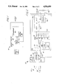
- FIG. 2 is a simplified schematic representation of transmitter 10 and main thermocouple 12.
- Main thermocouple 12 comprises thermocouple leads L1 and L2 which are connected to form main thermocouple junction J1.
- Transmitter 10 comprises first cavity 14 and second cavity 16. Cavities 14 and 16 are separated by cavity wall 18.
- Leads L1 and L2 of main thermocouple 12 are coupled to cold junction terminals 20 and 22 in cavity 14.
- Thermocouple leads L1 and L2 are typically formed of metals which are different from those comprising terminals 20 and 22. Therefore, cold junctions J2 and J3 are formed at the point where leads L1 and L2 are connected to terminals 20 and 22.
- Terminals 20 and 22 extend through cavity wall 18 into cavity 16.
- Cavity 16 contains converter 24 which, in this preferred embodiment, comprises junction J5 and temperature sensor 6 which includes resistive sensor 26 and current source 28.
- the converter also comprises multiplexer 30, analog-to-digital (A/D) converter 32, microprocessor-based controller 34 and output circuit 36.
- A/D analog-to-digital
- Converter leads L3 and L4 are connected to terminals 20 and 22, respectively. Also, converter leads L3 and L4 are coupled to multiplexer inputs I2, I4 and I6. In this arrangement, junctions J1, J2 and J3 are connected in electrical series to converter 24. Therefore, the signal appearing across multiplexer inputs I2 and I4 represents the combined potential resulting from junctions J1, J2 and J3.
- conductor C1 is connected between terminal 22 and converter lead L5 and is formed of a metal which is different from that of both terminal 22 and converter lead L5. Therefore, a correction thermocouple is formed having junctions J4 and J5. For this reason, terminal 22 is not only part of a cold junction in the thermocouple circuit comprising junctions J1, J2 and J3, but it is also part of the correction thermocouple circuit comprising thermocouple junctions J4 and J5.
- the temperature at junction J4 is closely matched to the temperature of cold junctions J2 and J3. Therefore, the correction thermocouple effectively senses the difference between the temperature of converter 24 and the cold junction temperature. This difference is provided to multiplexer 30 as a correction potential across multiplexer inputs I6 and I8.
- Resistive sensor 26 is located in cavity 16 where it is buffered or isolated from thermal transients in cavity 14. Resistive sensor 26, in combination with current source 28, provides a converter temperature signal, appearing as a potential across multiplexer inputs I10 and I12, to converter 24. The converter temperature signal represents the temperature of converter 24. It should be noted that any means of determining the temperature of converter 24 could be used instead of resistive sensor 26 as long as it is reasonably accurate.
- Cold junction compensation is effected by combining the converter temperature signal appearing across multiplexer inputs I10 and I12 with the correction signal from the correction thermocouple input appearing across multiplexer inputs I6 and I8. Based on this combination of inputs, microprocessor-based controller 34 calculates a correction constant which is substantially equivalent to a calculated cold junction potential. The correction constant is used by microprocessor-based controller 34 to compensate the combined temperature signal, appearing across multiplexer inputs I2 and I4, for the cold junction temperature.
- the value of the compensated signal (in this embodiment a potential) is then typically entered into a look-up table or a polynomial by microprocessor-based controller 34 to calculate an output representative of the temperature at junction J1 of main thermocouple 12.
- microprocessor-based controller 34 controls multiplexer 30 so that a selected pair of multiplexer inputs are connected to A/D converter 32.
- A/D converter 32 converts the thermocouple and temperature sensor signals to digital signals and provides them to microprocessor-based controller 34.
- microprocessor-based controller 34 Based on these inputs (as discussed above), microprocessor-based controller 34 provides control signals to output circuit 36 which, in turn, generates an output signal representative of the temperature at junction J1 of main thermocouple 12.
- the output signal is in the form of a 4-20 milliamp signal generated in current loop 38.
- FIG. 2 is effective when junctions J2 and J3 are closely matched in temperature.
- terminals 20 and 22 can have different temperatures.
- a second correction thermocouple circuit as shown in FIG. 3, is added to terminal 20 to provide more accurate compensation.
- FIG. 3 shows a simplified schematic representation of transmitter 10 and main thermocouple 12. This is identical to the embodiment shown in FIG. 2 except that conductor C2, converter lead L6, and multiplexer inputs I14 and I16 have been added. As with the first correction thermocouple described above, conductor C2 is of a different material than terminal 20 and lead L6. This effectively creates a second correction thermocouple which has junctions J6 and J7 and which provides converter 24 with a second correction signal representing the temperature difference between converter 24 and terminal 20.
- Microprocessor-based controller 34 now controls multiplexer 30 to multiplex the second correction signal, appearing across multiplexer inputs I14 and I16, into A/D converter 32 as well as the signals appearing across the other mulitplexer inputs.
- the second correction signal is also used to compensate the combined temperature signal, appearing across inputs I2 and I4 of multiplexor 30, for cold junction temperatures.
- Transmitter 10 is capable of operating with thermocouple 12 either being remote from transmitter 10 or being manufactured as an integral part of transmitter 10.
- This arrangement is substantially free of the effects of temperature lag experienced with methods of cold junction compensation which have resistors located on the terminal block.
- microprocessor-based controller 34 is reduced. This increases the speed with which transmitter 10 can respond to temperature changes.
Abstract
Description
Claims (7)
Priority Applications (7)
| Application Number | Priority Date | Filing Date | Title |
|---|---|---|---|
| US07/359,332 US4936690A (en) | 1989-05-31 | 1989-05-31 | Thermocouple transmitter with cold junction compensation |
| EP90907946A EP0474674B1 (en) | 1989-05-31 | 1990-04-23 | Thermocouple transmitter with cold junction compensation |
| AU55671/90A AU637796B2 (en) | 1989-05-31 | 1990-04-23 | Thermocouple transmitter with cold junction compensation |
| DE69020349T DE69020349T2 (en) | 1989-05-31 | 1990-04-23 | THERMOCOUPLE TRANSMITTER WITH COMPENSATION OF COLD SOLDERING POINTS. |
| BR909007402A BR9007402A (en) | 1989-05-31 | 1990-04-23 | TRANSMITTER TO GENERATE A BALANCE SIGNAL TEMPERATURE INDICATOR |
| PCT/US1990/002197 WO1990015314A1 (en) | 1989-05-31 | 1990-04-23 | Thermocouple transmitter with cold junction compensation |
| JP2507241A JP2880799B2 (en) | 1989-05-31 | 1990-04-23 | Thermocouple transmitter with cold junction compensation |
Applications Claiming Priority (1)
| Application Number | Priority Date | Filing Date | Title |
|---|---|---|---|
| US07/359,332 US4936690A (en) | 1989-05-31 | 1989-05-31 | Thermocouple transmitter with cold junction compensation |
Publications (1)
| Publication Number | Publication Date |
|---|---|
| US4936690A true US4936690A (en) | 1990-06-26 |
Family
ID=23413370
Family Applications (1)
| Application Number | Title | Priority Date | Filing Date |
|---|---|---|---|
| US07/359,332 Expired - Lifetime US4936690A (en) | 1989-05-31 | 1989-05-31 | Thermocouple transmitter with cold junction compensation |
Country Status (7)
| Country | Link |
|---|---|
| US (1) | US4936690A (en) |
| EP (1) | EP0474674B1 (en) |
| JP (1) | JP2880799B2 (en) |
| AU (1) | AU637796B2 (en) |
| BR (1) | BR9007402A (en) |
| DE (1) | DE69020349T2 (en) |
| WO (1) | WO1990015314A1 (en) |
Cited By (40)
| Publication number | Priority date | Publication date | Assignee | Title |
|---|---|---|---|---|
| DE4030926C1 (en) * | 1990-09-29 | 1992-04-16 | Heraeus Sensor Gmbh, 6450 Hanau, De | |
| US5130640A (en) * | 1990-06-28 | 1992-07-14 | Tegam, Inc. | Soldering iron testing apparatus |
| US5328264A (en) * | 1992-02-21 | 1994-07-12 | Sadis Bruker Spectrospin, Societe Anonyme De Diffusion De L'instrumentation Scientifique, Bruker Spectrospin | Compensation device for the cold junction of a thermocouple |
| US5353200A (en) * | 1993-02-24 | 1994-10-04 | Rosemount Inc. | Process transmitter with inner conductive cover for EMI shielding |
| US5484206A (en) * | 1993-12-28 | 1996-01-16 | Houldsworth; John | Method and apparatus for sensing a cold junction temperature |
| US5669713A (en) * | 1994-09-27 | 1997-09-23 | Rosemount Inc. | Calibration of process control temperature transmitter |
| US5803604A (en) * | 1996-09-30 | 1998-09-08 | Exergen Corporation | Thermocouple transmitter |
| DE19715080C1 (en) * | 1997-04-11 | 1998-10-15 | Hartmann & Braun Gmbh & Co Kg | Temperature sensor for remote operation employing thermocouple |
| US6293700B1 (en) * | 1999-09-24 | 2001-09-25 | Fluke Corporation | Calibrated isothermal assembly for a thermocouple thermometer |
| US6574515B1 (en) | 2000-05-12 | 2003-06-03 | Rosemount Inc. | Two-wire field-mounted process device |
| US20040255998A1 (en) * | 2003-06-17 | 2004-12-23 | Schuh William C. | Semi-compensated pins for cold junction compensation |
| US20050047479A1 (en) * | 2003-08-27 | 2005-03-03 | Underwood William Barry | Method, system and apparatus for measuring temperature with cold junction compensation |
| US20050080493A1 (en) * | 2003-10-14 | 2005-04-14 | Arntson Douglas W. | Two-wire field mounted process device |
| FR2870596A1 (en) * | 2004-05-24 | 2005-11-25 | Rosemount Aerospace Inc | THERMOCOUPLE MULTI-ELEMENT |
| US20050288799A1 (en) * | 2000-05-12 | 2005-12-29 | Brewer John P | Field-mounted process device |
| US20060050554A1 (en) * | 2004-09-09 | 2006-03-09 | Macronix International Co., Ltd. | Method and apparatus for operating nonvolatile memory cells in a series arrangement |
| US20060050555A1 (en) * | 2004-09-09 | 2006-03-09 | Macronix International Co., Ltd. | Method and apparatus for operating nonvolatile memory cells in a series arrangement |
| US20060050556A1 (en) * | 2004-09-09 | 2006-03-09 | Macronix International Co., Ltd. | Method and apparatus for operating charge trapping nonvolatile memory |
| US20060049448A1 (en) * | 2004-09-09 | 2006-03-09 | Macronix International Co., Ltd. | Method and apparatus for operating a string of charge trapping memory cells |
| US20060050565A1 (en) * | 2004-09-09 | 2006-03-09 | Macronix International Co., Ltd. | Method and apparatus for operating nonvolatile memory in a parallel arrangement |
| US20060050553A1 (en) * | 2004-09-09 | 2006-03-09 | Macronix International Co., Ltd. | Method and apparatus for sensing in charge trapping non-volatile memory |
| US20060055006A1 (en) * | 2004-09-16 | 2006-03-16 | Rosemount Inc. | Field device incorporating circuit card assembly as environmental and EMI/RFI shield |
| US20070019560A1 (en) * | 2005-07-19 | 2007-01-25 | Rosemount Inc. | Interface module with power over ethernet function |
| US20070107525A1 (en) * | 2005-11-17 | 2007-05-17 | Schnaare Theodore H | Process transmitter with overpressure vent |
| US7228186B2 (en) | 2000-05-12 | 2007-06-05 | Rosemount Inc. | Field-mounted process device with programmable digital/analog interface |
| US20070133273A1 (en) * | 2005-12-09 | 2007-06-14 | Macronix International Co., Ltd. | Gated diode nonvolatile memory cell |
| US20070133274A1 (en) * | 2005-12-09 | 2007-06-14 | Macronix International Co., Ltd. | Gated diode nonvolatile memory cell array |
| US20070131999A1 (en) * | 2005-12-09 | 2007-06-14 | Macronix International Co., Ltd. | Gated Diode Nonvolatile Memory Process |
| US20070133292A1 (en) * | 2005-12-09 | 2007-06-14 | Macronix International Co., Ltd. | Method for operating gated diode nonvolatile memory cell |
| WO2009071555A1 (en) * | 2007-12-03 | 2009-06-11 | Innovative Sensor Technology Ist Ag | Device for determining and/or monitoring temperature |
| US20100246630A1 (en) * | 2009-03-31 | 2010-09-30 | Rosemount Inc. | Thermocouple temperature sensor with connection detection circuitry |
| US20110071794A1 (en) * | 2009-09-22 | 2011-03-24 | Bronczyk Andrew J | Industrial process control transmitter with multiple sensors |
| RU2521746C1 (en) * | 2010-06-07 | 2014-07-10 | Роузмаунт Инк. | Transmitter of process parameters with determination of polarity of thermocouple |
| US20140238457A1 (en) * | 2013-02-22 | 2014-08-28 | Weston Aerospace Limited | Method of producing a thermocouple having a tailored thermoelectric response |
| WO2014137994A1 (en) * | 2013-03-05 | 2014-09-12 | Rosenthal Scott Bruce | Thermocouple circuit based temperature sensor |
| WO2015032592A1 (en) * | 2013-09-09 | 2015-03-12 | Endress+Hauser Wetzer Gmbh+Co. Kg | Method for determining the reference junction temperature of a thermocouple |
| US20160377489A1 (en) * | 2015-06-24 | 2016-12-29 | Lsis Co., Ltd. | Method for temperature drift compensation of temperature measurement device using thermocouple |
| US10234335B2 (en) | 2014-04-30 | 2019-03-19 | Thermo-Kinetics Company Limited | Thermocouple resistance compensator |
| US10260960B2 (en) | 2015-12-17 | 2019-04-16 | Honeywell International Inc. | System and method to mitigate abrupt environment temperature disturbances in cold junction of TC/RTD in control systems |
| US11159203B2 (en) | 2019-09-13 | 2021-10-26 | Micro Motion, Inc. | Process control loop bridge |
Families Citing this family (3)
| Publication number | Priority date | Publication date | Assignee | Title |
|---|---|---|---|---|
| DE102015113842A1 (en) * | 2015-08-20 | 2017-02-23 | Endress + Hauser Wetzer Gmbh + Co. Kg | Temperature measuring device with reference temperature determination |
| CN105628236A (en) * | 2015-12-20 | 2016-06-01 | 苏州长风航空电子有限公司 | Thermocouple temperature signal acquisition method |
| CN105651409B (en) * | 2016-04-06 | 2018-11-16 | 中国南方航空工业(集团)有限公司 | Cold junction compensation temperature measurement circuit and device |
Citations (5)
| Publication number | Priority date | Publication date | Assignee | Title |
|---|---|---|---|---|
| US3680384A (en) * | 1968-08-20 | 1972-08-01 | Rosemount Eng Co Ltd | Two wire telemetry system |
| US4130019A (en) * | 1977-06-09 | 1978-12-19 | Nitschke John Stephen | Self-compensating thermocouple reading circuit |
| US4157663A (en) * | 1978-04-25 | 1979-06-12 | The Boeing Company | Automatic thermocouple reference junction compensator |
| US4488824A (en) * | 1982-05-14 | 1984-12-18 | Mit Trading Corporation | Method and apparatus for precision temperature measurement |
| US4623266A (en) * | 1985-09-24 | 1986-11-18 | Rosemount Inc. | Cold junction compensation for thermocouple |
Family Cites Families (1)
| Publication number | Priority date | Publication date | Assignee | Title |
|---|---|---|---|---|
| US4624582A (en) * | 1984-02-29 | 1986-11-25 | Banda Lionel A | Multi-wire mineral insulated cable thermocouple reference junction |
-
1989
- 1989-05-31 US US07/359,332 patent/US4936690A/en not_active Expired - Lifetime
-
1990
- 1990-04-23 BR BR909007402A patent/BR9007402A/en not_active IP Right Cessation
- 1990-04-23 JP JP2507241A patent/JP2880799B2/en not_active Expired - Lifetime
- 1990-04-23 WO PCT/US1990/002197 patent/WO1990015314A1/en active IP Right Grant
- 1990-04-23 EP EP90907946A patent/EP0474674B1/en not_active Expired - Lifetime
- 1990-04-23 DE DE69020349T patent/DE69020349T2/en not_active Expired - Fee Related
- 1990-04-23 AU AU55671/90A patent/AU637796B2/en not_active Ceased
Patent Citations (5)
| Publication number | Priority date | Publication date | Assignee | Title |
|---|---|---|---|---|
| US3680384A (en) * | 1968-08-20 | 1972-08-01 | Rosemount Eng Co Ltd | Two wire telemetry system |
| US4130019A (en) * | 1977-06-09 | 1978-12-19 | Nitschke John Stephen | Self-compensating thermocouple reading circuit |
| US4157663A (en) * | 1978-04-25 | 1979-06-12 | The Boeing Company | Automatic thermocouple reference junction compensator |
| US4488824A (en) * | 1982-05-14 | 1984-12-18 | Mit Trading Corporation | Method and apparatus for precision temperature measurement |
| US4623266A (en) * | 1985-09-24 | 1986-11-18 | Rosemount Inc. | Cold junction compensation for thermocouple |
Cited By (69)
| Publication number | Priority date | Publication date | Assignee | Title |
|---|---|---|---|---|
| US5130640A (en) * | 1990-06-28 | 1992-07-14 | Tegam, Inc. | Soldering iron testing apparatus |
| DE4030926C1 (en) * | 1990-09-29 | 1992-04-16 | Heraeus Sensor Gmbh, 6450 Hanau, De | |
| US5328264A (en) * | 1992-02-21 | 1994-07-12 | Sadis Bruker Spectrospin, Societe Anonyme De Diffusion De L'instrumentation Scientifique, Bruker Spectrospin | Compensation device for the cold junction of a thermocouple |
| US5353200A (en) * | 1993-02-24 | 1994-10-04 | Rosemount Inc. | Process transmitter with inner conductive cover for EMI shielding |
| US5484206A (en) * | 1993-12-28 | 1996-01-16 | Houldsworth; John | Method and apparatus for sensing a cold junction temperature |
| US5669713A (en) * | 1994-09-27 | 1997-09-23 | Rosemount Inc. | Calibration of process control temperature transmitter |
| US5829876A (en) * | 1994-09-27 | 1998-11-03 | Rosemount Inc. | Calibration of process control temperature transmitter |
| US6045260A (en) * | 1994-09-27 | 2000-04-04 | Rosemount Inc. | Switch for selectively coupling a sensor or calibration element to a terminal block |
| US5803604A (en) * | 1996-09-30 | 1998-09-08 | Exergen Corporation | Thermocouple transmitter |
| DE19715080C1 (en) * | 1997-04-11 | 1998-10-15 | Hartmann & Braun Gmbh & Co Kg | Temperature sensor for remote operation employing thermocouple |
| US6293700B1 (en) * | 1999-09-24 | 2001-09-25 | Fluke Corporation | Calibrated isothermal assembly for a thermocouple thermometer |
| US20030181996A1 (en) * | 2000-05-12 | 2003-09-25 | Kirkpatrick William R. | Two-wire field-mounted process device |
| US6961624B2 (en) | 2000-05-12 | 2005-11-01 | Rosemount Inc. | Two-wire field-mounted process device |
| US6711446B2 (en) * | 2000-05-12 | 2004-03-23 | Rosemount, Inc. | Two-wire field-mounted process device |
| US20040158334A1 (en) * | 2000-05-12 | 2004-08-12 | Rosemount Inc. | Two-wire field-mounted process device |
| US20060161271A1 (en) * | 2000-05-12 | 2006-07-20 | Kirkpatrick William R | Two-wire field-mounted process device |
| US6574515B1 (en) | 2000-05-12 | 2003-06-03 | Rosemount Inc. | Two-wire field-mounted process device |
| US7228186B2 (en) | 2000-05-12 | 2007-06-05 | Rosemount Inc. | Field-mounted process device with programmable digital/analog interface |
| US7844365B2 (en) | 2000-05-12 | 2010-11-30 | Rosemount Inc. | Field-mounted process device |
| US20050288799A1 (en) * | 2000-05-12 | 2005-12-29 | Brewer John P | Field-mounted process device |
| US20040255998A1 (en) * | 2003-06-17 | 2004-12-23 | Schuh William C. | Semi-compensated pins for cold junction compensation |
| WO2005001402A3 (en) * | 2003-06-17 | 2007-09-13 | Watlow Electric Mfg | Semi-compensated pins for cold junction compensation |
| US20050155640A1 (en) * | 2003-06-17 | 2005-07-21 | Schuh William C. | Semi-compensated pins for cold junction compensation |
| US7994416B2 (en) | 2003-06-17 | 2011-08-09 | Watlow Electric Manufacturing Company | Semi-compensated pins for cold junction compensation |
| WO2005001402A2 (en) * | 2003-06-17 | 2005-01-06 | Watlow Electric Manufacturing Company | Semi-compensated pins for cold junction compensation |
| US7084342B2 (en) | 2003-06-17 | 2006-08-01 | Watlow Electric Manufacturing Co. | Semi-compensated pins for cold junction compensation |
| US7144155B2 (en) * | 2003-08-27 | 2006-12-05 | General Electric Company | Method, system and apparatus for measuring temperature with cold junction compensation |
| US20050047479A1 (en) * | 2003-08-27 | 2005-03-03 | Underwood William Barry | Method, system and apparatus for measuring temperature with cold junction compensation |
| US7016741B2 (en) | 2003-10-14 | 2006-03-21 | Rosemount Inc. | Process control loop signal converter |
| US20050080493A1 (en) * | 2003-10-14 | 2005-04-14 | Arntson Douglas W. | Two-wire field mounted process device |
| FR2870596A1 (en) * | 2004-05-24 | 2005-11-25 | Rosemount Aerospace Inc | THERMOCOUPLE MULTI-ELEMENT |
| US20060227849A1 (en) * | 2004-05-24 | 2006-10-12 | Rosemount Aerospace Inc. | Multi-element thermocouple |
| US7175343B2 (en) | 2004-05-24 | 2007-02-13 | Rosemount Aerospace | Multi-element thermocouple |
| US7044638B2 (en) | 2004-05-24 | 2006-05-16 | Rosemount Aerospace, Inc. | Multi-element thermocouple |
| US20060050554A1 (en) * | 2004-09-09 | 2006-03-09 | Macronix International Co., Ltd. | Method and apparatus for operating nonvolatile memory cells in a series arrangement |
| US20060049448A1 (en) * | 2004-09-09 | 2006-03-09 | Macronix International Co., Ltd. | Method and apparatus for operating a string of charge trapping memory cells |
| US20060050556A1 (en) * | 2004-09-09 | 2006-03-09 | Macronix International Co., Ltd. | Method and apparatus for operating charge trapping nonvolatile memory |
| US20060050555A1 (en) * | 2004-09-09 | 2006-03-09 | Macronix International Co., Ltd. | Method and apparatus for operating nonvolatile memory cells in a series arrangement |
| US20060050553A1 (en) * | 2004-09-09 | 2006-03-09 | Macronix International Co., Ltd. | Method and apparatus for sensing in charge trapping non-volatile memory |
| US20070069284A1 (en) * | 2004-09-09 | 2007-03-29 | Macronix International Co., Ltd. | Method and Apparatus for Operating a String of Charge Trapping Memory Cells |
| US20060050565A1 (en) * | 2004-09-09 | 2006-03-09 | Macronix International Co., Ltd. | Method and apparatus for operating nonvolatile memory in a parallel arrangement |
| US7550826B2 (en) | 2004-09-16 | 2009-06-23 | Rosemount Inc. | Field device incorporating circuit card assembly as environmental and EMI/RFI shield |
| US7190053B2 (en) | 2004-09-16 | 2007-03-13 | Rosemount Inc. | Field device incorporating circuit card assembly as environmental and EMI/RFI shield |
| US20060055006A1 (en) * | 2004-09-16 | 2006-03-16 | Rosemount Inc. | Field device incorporating circuit card assembly as environmental and EMI/RFI shield |
| US20070138602A1 (en) * | 2004-09-16 | 2007-06-21 | Orth Kelly M | Field device incorporating circuit card assembly as environmental and EMI/RFI shield |
| US7835295B2 (en) | 2005-07-19 | 2010-11-16 | Rosemount Inc. | Interface module with power over Ethernet function |
| US20070019560A1 (en) * | 2005-07-19 | 2007-01-25 | Rosemount Inc. | Interface module with power over ethernet function |
| US20070107525A1 (en) * | 2005-11-17 | 2007-05-17 | Schnaare Theodore H | Process transmitter with overpressure vent |
| US7287432B2 (en) | 2005-11-17 | 2007-10-30 | Rosemount Inc. | Process transmitter with overpressure vent |
| US20070133292A1 (en) * | 2005-12-09 | 2007-06-14 | Macronix International Co., Ltd. | Method for operating gated diode nonvolatile memory cell |
| US20070133274A1 (en) * | 2005-12-09 | 2007-06-14 | Macronix International Co., Ltd. | Gated diode nonvolatile memory cell array |
| US20070133273A1 (en) * | 2005-12-09 | 2007-06-14 | Macronix International Co., Ltd. | Gated diode nonvolatile memory cell |
| US20070131999A1 (en) * | 2005-12-09 | 2007-06-14 | Macronix International Co., Ltd. | Gated Diode Nonvolatile Memory Process |
| WO2009071555A1 (en) * | 2007-12-03 | 2009-06-11 | Innovative Sensor Technology Ist Ag | Device for determining and/or monitoring temperature |
| US20100246630A1 (en) * | 2009-03-31 | 2010-09-30 | Rosemount Inc. | Thermocouple temperature sensor with connection detection circuitry |
| WO2010117427A1 (en) * | 2009-03-31 | 2010-10-14 | Rosemount Inc. | Thermocouple temperature sensor with connection detection circuitry |
| US8118484B2 (en) | 2009-03-31 | 2012-02-21 | Rosemount Inc. | Thermocouple temperature sensor with connection detection circuitry |
| US8311778B2 (en) | 2009-09-22 | 2012-11-13 | Rosemount Inc. | Industrial process control transmitter with multiple sensors |
| US20110071794A1 (en) * | 2009-09-22 | 2011-03-24 | Bronczyk Andrew J | Industrial process control transmitter with multiple sensors |
| RU2521746C1 (en) * | 2010-06-07 | 2014-07-10 | Роузмаунт Инк. | Transmitter of process parameters with determination of polarity of thermocouple |
| US20140238457A1 (en) * | 2013-02-22 | 2014-08-28 | Weston Aerospace Limited | Method of producing a thermocouple having a tailored thermoelectric response |
| US9786828B2 (en) * | 2013-02-22 | 2017-10-10 | Weston Aerospace Limited | Method of producing a thermocouple having a tailored thermoelectric response |
| WO2014137994A1 (en) * | 2013-03-05 | 2014-09-12 | Rosenthal Scott Bruce | Thermocouple circuit based temperature sensor |
| WO2015032592A1 (en) * | 2013-09-09 | 2015-03-12 | Endress+Hauser Wetzer Gmbh+Co. Kg | Method for determining the reference junction temperature of a thermocouple |
| US10234335B2 (en) | 2014-04-30 | 2019-03-19 | Thermo-Kinetics Company Limited | Thermocouple resistance compensator |
| US20160377489A1 (en) * | 2015-06-24 | 2016-12-29 | Lsis Co., Ltd. | Method for temperature drift compensation of temperature measurement device using thermocouple |
| US10101217B2 (en) * | 2015-06-24 | 2018-10-16 | Lsis Co., Ltd. | Method for temperature drift compensation of temperature measurement device using thermocouple |
| US10260960B2 (en) | 2015-12-17 | 2019-04-16 | Honeywell International Inc. | System and method to mitigate abrupt environment temperature disturbances in cold junction of TC/RTD in control systems |
| US11159203B2 (en) | 2019-09-13 | 2021-10-26 | Micro Motion, Inc. | Process control loop bridge |
Also Published As
| Publication number | Publication date |
|---|---|
| JP2880799B2 (en) | 1999-04-12 |
| BR9007402A (en) | 1992-04-28 |
| WO1990015314A1 (en) | 1990-12-13 |
| EP0474674A1 (en) | 1992-03-18 |
| DE69020349T2 (en) | 1996-02-29 |
| AU637796B2 (en) | 1993-06-10 |
| EP0474674B1 (en) | 1995-06-21 |
| DE69020349D1 (en) | 1995-07-27 |
| EP0474674A4 (en) | 1992-05-06 |
| AU5567190A (en) | 1991-01-07 |
| JPH04505504A (en) | 1992-09-24 |
Similar Documents
| Publication | Publication Date | Title |
|---|---|---|
| US4936690A (en) | Thermocouple transmitter with cold junction compensation | |
| EP0147700B1 (en) | Apparatus for temperature compensation in a digital data handling system | |
| US4130019A (en) | Self-compensating thermocouple reading circuit | |
| US4588308A (en) | Temperature measuring device with thermocouple | |
| US4623266A (en) | Cold junction compensation for thermocouple | |
| US3562729A (en) | Two wire mv./v. transmitter | |
| US4796212A (en) | Load cell type, weight-measuring device | |
| US3680384A (en) | Two wire telemetry system | |
| US4777428A (en) | Device for compensation of transfer functions | |
| US3218859A (en) | Temperature measuring systems | |
| US4724709A (en) | Pressure measuring system with internal reference | |
| JPS6224121A (en) | Measuring head | |
| JPH09133588A (en) | Zero contact compensator and compensation method for temperature measuring apparatus | |
| US3483751A (en) | Device for determining the temperature of electrical apparatus | |
| US3307402A (en) | Compensated tapped thermocouple system | |
| US2877650A (en) | Self-balancing temperature responsive system | |
| JPS6147371B2 (en) | ||
| US3956686A (en) | Compensating circuit for a cold junction of a thermocouple | |
| USRE27596E (en) | Two-wire mv./v. transmitter | |
| US3022669A (en) | Rate sensitive thermocouple | |
| US2509048A (en) | Temperature responsive measuring apparatus | |
| WO1987004788A1 (en) | Temperature measuring device capable of changing display unit | |
| WO1990013009A1 (en) | Electronic circuit arrangement | |
| GB2082774A (en) | Thermocouple Cold Junction Compensation | |
| JP3210222B2 (en) | Temperature measuring device |
Legal Events
| Date | Code | Title | Description |
|---|---|---|---|
| AS | Assignment |
Owner name: ROSEMOUNT INC., 12001 TECHNOLOGY DRIVE, EDEN PRAIR Free format text: ASSIGNMENT OF ASSIGNORS INTEREST.;ASSIGNOR:GOETZINGER, CHARLES E.;REEL/FRAME:005086/0635 Effective date: 19890531 |
|
| STCF | Information on status: patent grant |
Free format text: PATENTED CASE |
|
| FEPP | Fee payment procedure |
Free format text: PAYER NUMBER DE-ASSIGNED (ORIGINAL EVENT CODE: RMPN); ENTITY STATUS OF PATENT OWNER: LARGE ENTITY Free format text: PAYOR NUMBER ASSIGNED (ORIGINAL EVENT CODE: ASPN); ENTITY STATUS OF PATENT OWNER: LARGE ENTITY |
|
| FEPP | Fee payment procedure |
Free format text: PAYOR NUMBER ASSIGNED (ORIGINAL EVENT CODE: ASPN); ENTITY STATUS OF PATENT OWNER: LARGE ENTITY |
|
| FPAY | Fee payment |
Year of fee payment: 4 |
|
| FPAY | Fee payment |
Year of fee payment: 8 |
|
| FPAY | Fee payment |
Year of fee payment: 12 |