US4936790A - Low insertion force connector - Google Patents
Low insertion force connector Download PDFInfo
- Publication number
- US4936790A US4936790A US07/345,763 US34576389A US4936790A US 4936790 A US4936790 A US 4936790A US 34576389 A US34576389 A US 34576389A US 4936790 A US4936790 A US 4936790A
- Authority
- US
- United States
- Prior art keywords
- card
- contacts
- coupled
- housing
- coupling
- Prior art date
- Legal status (The legal status is an assumption and is not a legal conclusion. Google has not performed a legal analysis and makes no representation as to the accuracy of the status listed.)
- Expired - Lifetime
Links
Images


Classifications
-
- H—ELECTRICITY
- H01—ELECTRIC ELEMENTS
- H01R—ELECTRICALLY-CONDUCTIVE CONNECTIONS; STRUCTURAL ASSOCIATIONS OF A PLURALITY OF MUTUALLY-INSULATED ELECTRICAL CONNECTING ELEMENTS; COUPLING DEVICES; CURRENT COLLECTORS
- H01R12/00—Structural associations of a plurality of mutually-insulated electrical connecting elements, specially adapted for printed circuits, e.g. printed circuit boards [PCB], flat or ribbon cables, or like generally planar structures, e.g. terminal strips, terminal blocks; Coupling devices specially adapted for printed circuits, flat or ribbon cables, or like generally planar structures; Terminals specially adapted for contact with, or insertion into, printed circuits, flat or ribbon cables, or like generally planar structures
- H01R12/70—Coupling devices
- H01R12/82—Coupling devices connected with low or zero insertion force
- H01R12/85—Coupling devices connected with low or zero insertion force contact pressure producing means, contacts activated after insertion of printed circuits or like structures
- H01R12/87—Coupling devices connected with low or zero insertion force contact pressure producing means, contacts activated after insertion of printed circuits or like structures acting automatically by insertion of rigid printed or like structures
Definitions
- This invention relates to the field of connection systems and, more specifically, to the field of connection systems for modular card devices.
- connection systems In the field of connection systems, numerous methods exist for coupling various types of cards or devices to computer systems or to other devices. For example, coupling of printed circuit boards to computer systems is often accomplished using a plated set of connection pads on a tab on the printed circuit board. The tab is inserted into a socket coupled with a computer system. Use of this method typically requires side-to-side movement of the printed circuit board in order to properly seat the printed circuit board in the socket.
- Pine and socket connection systems are also well known. These connection systems involve a device having a set of pins which may be coupled with a set of sockets on the computer system or other device.
- the pin connector on the card is often called the male connector.
- the socket connector on the computer is often called the female connector.
- the female conductor may be on the card and the male connector on the computer system.
- Coupling using the pin and socket connection system poses several problems. First, a large amount of force is generally required to insert the male connector into the female connector. Second, insertion of the male connector into the female connector typically requires side-to-side movement of the card which in turn requires use of several fingers or possible both hands. Third, bending of the pins and wear on the pins and sockets is common.
- the present invention discloses a connection system which allows coupling of a card to a computer system or other device.
- the present invention utilizes a rack of sliding contacts to ensure ease of insertion of the card into the connection system.
- the rack of sliding contacts slides backwards as the card is inserted, forcing back a spring device.
- the rack of sliding contacts is coupled with the card as the rack slides backwards. When the rack reaches its final insertion position an audible and tactile "click" occurs.
- the present invention avoids the prior art problems of bending of pins and wear on the connection system.
- the rack of sliding contacts design allows insertion and removal of cards with a very small amount of pressure, such that the cards may be inserted or removed easily with one finger.
- the present invention further discloses use of a roller assembly to reduce friction when inserting a card and use of an inertia latch mechanism which reduces the possibility of inadvertent release of the card.
- FIG. 1(a) illustrates a prior art pin connector
- FIG. 1(b) illustrates a prior art socket connector
- FIG. 2(a) is a perspective view of a card which may be inserted into a connection system as disclosed by the present invention.
- FIG. 2(b) is a top view of the card which may be inserted into the connection system of the present invention.
- FIG. 3(a) is a block diagram illustrating the card being inserted into the connection system of the present invention.
- FIG. 3(b) is a block diagram illustrating the card inserted in the connection system of the present invention.
- FIG. 3(c) is a block diagram illustrating the card fully inserted in the connection system of the present invention.
- FIG. 4 is a perspective view of the top inside of the connection system housing of the present invention.
- FIG. 5 is a perspective view of the bottom inside of the connection system housing of the present invention.
- FIG. 6(a) is an explosion view of a sliding rack of connectors as utilized by the present invention.
- FIG. 6(b) is a bottom view of the sliding rack of connectors.
- FIG. 6(c) is a top view of the sliding rack of connectors with a ribbon cable attached.
- FIG. 7 is a perspective view of a locking mechanism as utilized by the present invention.
- FIG. 8 is an explosion view of a spring assembly as utilized by the present invention.
- FIG. 9 is a side view of a leaf spring as utilized by the present invention.
- FIG. 10 is a perspective view of a shutter actuator as utilized by the present invention.
- FIG. 11 is an explosion view of a second embodiment of the present invention.
- a low insertion force connection apparatus is described.
- numerous specific details are set forth such as types of materials, types of cables, etc., in order to provide a thorough understanding of the present invention. It will be obvious, however, to one skilled in the art that the present invention may be practiced without these specific details. In other instances, well-known structures and techniques have not been shown in detail in order not to unnecessarily obscure the present invention.
- FIGS. 1(a) and FIG. 1(b) are illustrative of one prior art method for coupling cards with computer systems or other devices.
- FIG. 1(a) illustrates a pin connector 1 which may be attached to a card.
- FIG. 1(b) illustrates a socket connector 3 which may be attached to a computer system.
- the pin connector 1 may be coupled with the socket connector 3 by inserting the pin connector 1 into the socket connector 3.
- the pins 2 are thereby inserted into the sockets 4. In this manner, the card is electrically coupled to the computer system.
- This method of coupling cards with computer systems poses several problems.
- the present invention is designed to overcome these prior art problems and provide a method of inserting a card into a computer system or other device with minimal force and with minimal wear on the connections and chance for breakage or damage to the connection system.
- FIGS. 2(a) and FIG. 2(b) are illustrative of cards which may be inserted into the connection system of the present invention.
- these cards 20 may have memory circuitry in the form of either read only memory (ROM) or random access memory (RAM) and may be of various speeds and configurations. It will be obvious to one of ordinary skill in the art that other types of cards may easily be used in the connection system disclosed by the present invention.
- the cards 20 of the preferred embodiment have a shutter 21 that closes over the connectors when the card is not inserted into the connection system. It will be seen that the present invention supplies apparatuses for moving the shutter 231 back to expose the connectors when the card is inserted in the connection system housing. It is appreciated that the present invention will work without the shutter 21 and that the shutter is provided in the preferred embodiment for the protection of the connectors.
- FIGS. 3(a), 3(b), 3(c), 4, 5, 6(a), 6(b), 6(c), 7, 8, 9 and 10 are illustrative of a first embodiment of the present invention.
- a rack of sliding connectors are employed to electrically couple the card 20 of FIGS. 2(a) and 2(b) to a computer system.
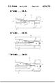
- FIGS. 3(a), 3(b), 3(c) are illustrative of inserting a card into the connection system, the card being seated in its normal inserted position in the connection system, and the card being released from the connection system, respectively.
- the card 20 is inserted into the connection system housing and rests on the rack of sliding contacts 31. In this position, the contacts 33 are not yet coupled with the card 20 at connection point 39.
- the rack of sliding contacts 31 sits on the bottom of the connection system housing 35.
- a contact bar 32 rests along the top of the connection system housing 36. In this position, the spring 30 is uncompressed. It will be seen in connection with FIG. 3(b) that as the rack of sliding contacts 31 is pushed back by the card 20 the contact bar 32 slides down the sloped area 398 making contact with the card 20 at connection pint 39.
- FIG. 3(b) illustrates the card fully inserted into the connection system housing.
- the rack of sliding contacts 31 has been pushed back forcing the spring 30 into a compressed state.
- the contact bar 32 has moved down the sloped area 38 on the top of the connection system housing 36. This forces the contacts 33 to be coupled with the card 20 at connection point 39.
- the shutter 21 illustrated in FIG. 2 is moved back by two shutter actuators mounted on both sides of the top of the connection system housing 36. These shutter actuators and the shutter are not shown in this figure. Moving back the shutter exposes the connectors on the card 20 as previously discussed in connection with FIGS. 2(a) and 2(b).
- the spring mechanism When the card 20 reaches its fully inserted position, shown by FIG. 3(b) the spring mechanism produces an audible and tactile click. This lets the user of the connection system know that the card has been properly inserted.
- This method of inserting the card 20 into the rack of sliding contacts 31 produces minimal wear on the contacts on the card 20 and the on contacts 33 in the sliding rack 31.
- insertion of the card into the connection system requires very little force. Typically insertion can be accomplished easily with a single finger.
- connection system To release the card from the connection system a small amount of force is applied to the card typically with a single finger. As illustrated in FIG. 3(c), this moves the card 20 and the rack of sliding contacts 31 back slightly and further compresses the spring 30. Pushing the card 20 back to the release position causes another audible and tactile click. The spring mechanism then releases, uncompressing the spring 30 and moving the rack of sliding contacts 31 and the card 20 forward. The card 20 may then be easily removed from the connection system housing 40.
- FIG. 4 illustrates the top inside of the connection system housing 40 as utilized in the first embodiment of the present invention.
- the card 20 is inserted into the computer system housing 40 through the slot opening formed by notch 49(a) at the front of the computer system housing 40.
- the card 20 is then guided into place with the guide rails 47(a) and 47(b) and the leaf springs 41 along the sides of the top of the computer system housing 40.
- the top of the computer system housing 40 is coupled with the bottom of the computer system housing using the linkage mounts 43.
- the two linkage mounts 43 on one side of the computer system housing 40 have rounded notches 42 to hold a locking rod.
- the lock rod will be more fully described in connection with FIG. 7.
- the top of the computer system housing 40 also has a notch 44 cut to accommodate the locking mechanism.
- the locking mechanism will be more fully described in connection with FIGS. 6(a), 6(b), 6(c) and 7.
- One shutter actuator 45 is illustrated attached to one side of the connection system housing 40.
- Another shutter actuator (not shown) is attached to the opposite side of the connection system housing 40 near the slot 44 for the locking mechanism. These shutter actuators 45 are used to open the shutter 21 shown in connection with FIGS. 2(a) and 2(b).
- FIG. 5 is illustrative of the bottom of the connection system housing 50.
- the bottom of the connection system housing 50 has linkage mounts 46 corresponding with linkage mounts 43 on the top of the connection system housing 40. Two of these linkage mounts 46 also have rounded notches 42 cut to accommodate the locking rod mechanism.
- a notch 49(b) is cut in the front of the bottom of the connection system housing 50 and corresponding with the notch cut in the top of the connection system housing 40 to allow the card to be inserted.
- Another notch 44 is cut in the side of the bottom of the connection system housing 50 to accommodate the locking mechanism and corresponds with the notch cut in the top of the connection system housing 40.
- Guide rails 47(c) and 47(d) are provided to assist with alignment of the card as it is being inserted.
- connection system housing 50 contains the spring assembly 51, the function of which was described in connection with FIGS. 3(a), 3(b) and 3(c).
- the components of the spring assembly 51 will be more fully described in connection with FIG. 8.
- FIG. 4 and FIG. 5 illustrates the connection system housing without the rack of sliding contacts.
- the rack of sliding contacts will be more fully described in connection with FIGS. 6(a), 6(b) and 6(c).
- FIG. 6(a) is a bottom side explosion view of the rack of sliding contacts.
- the sliding rack 60 has post holes 63 for coupling with the contact assembly 61.
- the contact assembly 61 has posts 62 which are inserted into the post holes 63 when the rack of sliding contacts is assembled.
- the sliding rack 60 also has a notch 66 cut to accommodate the spring assembly shown in FIG. 5 and has side mounts 67. Coupled with one of the side mounts 67 is a holder 65 for holding the locking rod. This holder 65 embodies a hole 64 for holding the rod.
- the contact assembly 61 comprises the contact bar more fully described in connection with FIGS. 3(a), 3(b) and 3(c), contacts 33 and the post 62.
- the contacts 33 have a bend 68 for coupling with the contacts on the card.
- the posts 62 are inserted into the post holes 63 of the sliding rack 60.
- FIG. 6(b) illustrates the sliding rack assembly with the contact assembly 61 and the rod holder 65 coupled with it.
- FIG. 6(c) illustrates the top side of the assembled contact assembly 61 and sliding rack 60.
- a flexible circuit 69 is coupled with the contacts 33 on the contact assembly 61.
- the flexible circuit 69 is used for coupling with the computer system or other device.
- An alternative is the use of ribbon cable in place of the flexible circuit 69.
- FIG. 7 illustrates a locking rod 70 as may be utilized by the present invention.
- the locking rod 70 is held in place as previously described in connection with FIGS. 4 and 5 by the slots in the linkage mounts on the top and bottom of the connection system housing.
- the locking rod 70 goes through the hole in the rod holder as described in conjunction with FIGS. 6(a) and 6(b).
- the tabs 71 on the rod 70 allow the sliding rack to move back and forth freely when the rod 70 is turned in one position by passing back and forth in a slot cut for them in the rod holder. When the rod 70 is turned 90° the tabs 71 will not align with the slots cut for them and will hold the sliding rack in its inserted position.
- FIG. 8 further illustrates the spring assembly utilized in the present invention.
- the spring pusher apparatus 83 coupled with the sliding rack in the notch provided therein.
- the cam holder 81 couples with the pusher and the spring 82.
- the cover 80 is then placed over the top of the spring assembly when the spring assembly is assembled in the bottom of the connection housing.
- FIG. 9 illustrates a leaf spring 41 which is used to guide the card into the connection housing assembly and to minimize back and forth movement when the card is in its fully inserted position.
- the leaf spring 41 comprises a strip of metal 95 which is wide at one end 93.
- the wide end 93 embodies two screw holes 91.
- the screw holes 91 are for coupling with the connection system housing.
- FIG. 10 illustrates a shutter actuator 45 for causing the shutter on the card to open as it is inserted into the connection system housing.
- Two shutter actuators 45 are coupled with the top of the connection system housing as was illustrated in connection with FIG. 4.
- FIG. 11 is an explosion view of a second embodiment of the present invention. This embodiment illustrates several inventive advantages over the first embodiment and is currently the preferred embodiment of the present invention.
- the second embodiment comprises an uppercase cover 100 and a lowercase cover 111. Once a low insertion force connector is assembled, it may be stacked with other low insertion force connectors in a single assembly.
- the second embodiment utilizes a plurality of rollers 104 and 110 which reduces sliding friction encountered in the first embodiment.
- the rolling friction encountered in this embodiment has been shown to have an approximately 20:1 advantage over the sliding friction of the first embodiment.
- the rollers 104 and 110 concentrate the contact load forces on the edge of the case and thereby minimize the case deflections, as the steel rollers carry the loads rather than the plastic case.
- rolling the contacts 113 instead of sliding the contacts, when engaging with the slim card eliminates build up of stresses in the contacts 113 during initial non-engaged travel and reduces frictional abrasion on the slim card.
- the slim card is normally inserted into the connector through slot 114 where it engages shutter retracting teeth (not shown) so that the shutter is fully retracted when the card contacts the rear of upper carriage assembly 108.
- the slim card contacting with the carriage assembly moves the carriage assembly to the rear of the case.
- the lower carriage assembly 116 begins to move upward on ramp 115 until the contacts 113 are fully engaged with the slim card.
- the ramp 115 flattens out in order to allow the carriage assembly to travel directly to the rear of the case approximately 0.050 inches which allows a pawl 105 in an audible latch mechanism to move into an engaged position without over stressing the contacts 113.
- the slim card and carriage assembly move forward approximately 0.045 inches, being driven by eject springs 107 until the pawl 105 contacts a latching island (not shown) in the uppercase.
- the pawl 105 moves past the latching island and removal of the finger pressure allows the eject springs 107 to eject the card.
- the inertial latch mechanism comprises an inertia latch spring 101, inertia latch 102, inertia latch weight 103, and a second inertia latch spring 106 coupled with the pawl 105.
- the inertial latch mechanism is coupled with the latching island.
- a locking feature 117 is provided on the front corner of the case 111.
- the locking feature 117 comprises a spring loaded device which engages a notch on the side of the slim card.
- the notch may be optionally provided on cards where casual disengagement of the card is not desired.
- such a notch may be provided on a ROM slim card. Unlocking of cards with such a notch is accomplished by inserting a pin or other device such as a paper clip into an access hole 118. A force of approximately 1.7 pounds will deflect the spring on the locking mechanism 117 enough to disengage the card from it at which point finger pressure on the front of the card will disengage the card in the manner previously described.
- a flex circuit 109 which is soldered terminated to the contacts 113.
- the flex circuit is strain relieved by screws 119 which hold a contact header 120 to the lower carriage assembly 116.
- the flex circuit 109 is also strain relieved where it exits the case at point 121.
- the length of the flex circuit between these strain relieves is longer than the distant between them in the disengaged position of the carriage assembly. This forces the flex circuit into a gentle s-bend. Moving the carriage toward the rear of the case during insertion of the card deepens this s-bend which distributes the bending stresses evenly along the enclosed length of the flex circuit.
- connection system for coupling a memory card or other device to a computer system or other device with minimal insertion force is described.
Abstract
Description
Claims (11)
Priority Applications (1)
| Application Number | Priority Date | Filing Date | Title |
|---|---|---|---|
| US07/345,763 US4936790A (en) | 1989-04-28 | 1989-04-28 | Low insertion force connector |
Applications Claiming Priority (1)
| Application Number | Priority Date | Filing Date | Title |
|---|---|---|---|
| US07/345,763 US4936790A (en) | 1989-04-28 | 1989-04-28 | Low insertion force connector |
Publications (1)
| Publication Number | Publication Date |
|---|---|
| US4936790A true US4936790A (en) | 1990-06-26 |
Family
ID=23356380
Family Applications (1)
| Application Number | Title | Priority Date | Filing Date |
|---|---|---|---|
| US07/345,763 Expired - Lifetime US4936790A (en) | 1989-04-28 | 1989-04-28 | Low insertion force connector |
Country Status (1)
| Country | Link |
|---|---|
| US (1) | US4936790A (en) |
Cited By (13)
| Publication number | Priority date | Publication date | Assignee | Title |
|---|---|---|---|---|
| US5074797A (en) * | 1989-07-21 | 1991-12-24 | Thomas & Betts Corporation | Electrical Connector for Connecting Heat Seal Film to a Printed Wiring Board |
| US5554840A (en) * | 1994-03-07 | 1996-09-10 | American Magnetics Corporation | Hybrid card reader |
| US5637001A (en) * | 1994-01-13 | 1997-06-10 | The Whitaker Corporation | PCMCIA connection device |
| US5726922A (en) * | 1994-01-03 | 1998-03-10 | International Business Machines Corp. | Assembly for removably connecting data storage devices |
| US6116933A (en) * | 1998-10-22 | 2000-09-12 | Itt Manufacturing Enterprises, Inc. | Card reader |
| US6231363B1 (en) * | 1999-06-28 | 2001-05-15 | Itt Manufacturing Enterprises, Inc. | Low profile interconnection |
| US6517376B1 (en) * | 2001-10-30 | 2003-02-11 | Chin-Hwa Hwang | Positioning-sounding device for card puller |
| US6942149B2 (en) * | 2000-09-19 | 2005-09-13 | International Business Machines Corporation | Connecting structure of card, card, and computer system |
| WO2009150649A1 (en) * | 2008-06-11 | 2009-12-17 | Modu Ltd. | Push-to-insert, push-to-eject and pull-to-extract card connector |
| US8484671B1 (en) | 2003-10-07 | 2013-07-09 | The Directv Group, Inc. | Receiver interface with multiple access cards |
| US20140127922A1 (en) * | 2012-11-08 | 2014-05-08 | Tyco Electronics Japan G.K. | Connector |
| US20170133774A1 (en) * | 2015-11-10 | 2017-05-11 | DAl-ICHI SEIKO CO., LTD. | Electric connector |
| US9772662B1 (en) * | 2016-03-22 | 2017-09-26 | Western Digital Technologies, Inc. | Linear push-push mechanism for removable storage cartridge system |
Citations (6)
| Publication number | Priority date | Publication date | Assignee | Title |
|---|---|---|---|---|
| US4496213A (en) * | 1982-10-29 | 1985-01-29 | International Telephone And Telegraph Corporation | Audible indicator for a connector |
| US4592608A (en) * | 1983-12-14 | 1986-06-03 | Daiichi Denshi Kogyo Kabushiki Kaisha | Connector for memory cards |
| US4724310A (en) * | 1984-07-02 | 1988-02-09 | Tokyo Tatsuno Co., Ltd. | Device for inserting and holding an IC card as an external memory during reading and writing operations |
| US4795897A (en) * | 1986-02-21 | 1989-01-03 | U.S. Philips Corp. | Apparatus for establishing data transfers with a portable electronic card |
| US4810203A (en) * | 1986-12-27 | 1989-03-07 | Hosiden Electronics Co., Ltd. | Electrical connector |
| US4839509A (en) * | 1987-06-19 | 1989-06-13 | Diesel Kiki Co., Ltd. | Connector device for connecting IC card to reading and/or writing apparatus |
-
1989
- 1989-04-28 US US07/345,763 patent/US4936790A/en not_active Expired - Lifetime
Patent Citations (6)
| Publication number | Priority date | Publication date | Assignee | Title |
|---|---|---|---|---|
| US4496213A (en) * | 1982-10-29 | 1985-01-29 | International Telephone And Telegraph Corporation | Audible indicator for a connector |
| US4592608A (en) * | 1983-12-14 | 1986-06-03 | Daiichi Denshi Kogyo Kabushiki Kaisha | Connector for memory cards |
| US4724310A (en) * | 1984-07-02 | 1988-02-09 | Tokyo Tatsuno Co., Ltd. | Device for inserting and holding an IC card as an external memory during reading and writing operations |
| US4795897A (en) * | 1986-02-21 | 1989-01-03 | U.S. Philips Corp. | Apparatus for establishing data transfers with a portable electronic card |
| US4810203A (en) * | 1986-12-27 | 1989-03-07 | Hosiden Electronics Co., Ltd. | Electrical connector |
| US4839509A (en) * | 1987-06-19 | 1989-06-13 | Diesel Kiki Co., Ltd. | Connector device for connecting IC card to reading and/or writing apparatus |
Cited By (18)
| Publication number | Priority date | Publication date | Assignee | Title |
|---|---|---|---|---|
| US5074797A (en) * | 1989-07-21 | 1991-12-24 | Thomas & Betts Corporation | Electrical Connector for Connecting Heat Seal Film to a Printed Wiring Board |
| US5726922A (en) * | 1994-01-03 | 1998-03-10 | International Business Machines Corp. | Assembly for removably connecting data storage devices |
| US5637001A (en) * | 1994-01-13 | 1997-06-10 | The Whitaker Corporation | PCMCIA connection device |
| US5554840A (en) * | 1994-03-07 | 1996-09-10 | American Magnetics Corporation | Hybrid card reader |
| US6116933A (en) * | 1998-10-22 | 2000-09-12 | Itt Manufacturing Enterprises, Inc. | Card reader |
| US6231363B1 (en) * | 1999-06-28 | 2001-05-15 | Itt Manufacturing Enterprises, Inc. | Low profile interconnection |
| US6942149B2 (en) * | 2000-09-19 | 2005-09-13 | International Business Machines Corporation | Connecting structure of card, card, and computer system |
| US6517376B1 (en) * | 2001-10-30 | 2003-02-11 | Chin-Hwa Hwang | Positioning-sounding device for card puller |
| US8484671B1 (en) | 2003-10-07 | 2013-07-09 | The Directv Group, Inc. | Receiver interface with multiple access cards |
| US20090311903A1 (en) * | 2008-06-11 | 2009-12-17 | Modu Ltd. | Push-to-insert, push-to-eject and pull-to-extract card connector |
| US7997914B2 (en) | 2008-06-11 | 2011-08-16 | Google Inc. | Push-to-insert, push-to-eject and pull-to-extract card connector |
| US8337224B2 (en) | 2008-06-11 | 2012-12-25 | Google Inc. | Push-to-insert, push-to-eject and pull-to-extract card connector |
| WO2009150649A1 (en) * | 2008-06-11 | 2009-12-17 | Modu Ltd. | Push-to-insert, push-to-eject and pull-to-extract card connector |
| US20140127922A1 (en) * | 2012-11-08 | 2014-05-08 | Tyco Electronics Japan G.K. | Connector |
| US9780473B2 (en) * | 2012-11-08 | 2017-10-03 | Tyco Electronics Japan G.K. | Mating connector using slider to deform contacts |
| US20170133774A1 (en) * | 2015-11-10 | 2017-05-11 | DAl-ICHI SEIKO CO., LTD. | Electric connector |
| US9793629B2 (en) * | 2015-11-10 | 2017-10-17 | Dai-Ichi Seiko Co., Ltd. | Electric connector |
| US9772662B1 (en) * | 2016-03-22 | 2017-09-26 | Western Digital Technologies, Inc. | Linear push-push mechanism for removable storage cartridge system |
Similar Documents
| Publication | Publication Date | Title |
|---|---|---|
| US6371787B1 (en) | Pull-to-release type latch mechanism for removable small form factor electronic modules | |
| US5548484A (en) | IC card-receiving host | |
| US4936790A (en) | Low insertion force connector | |
| US5149276A (en) | Modular holder having an ejector mechanism for a dual IC package | |
| US5222897A (en) | Circuit board inserter/ejector system | |
| US6129572A (en) | Electrical connector with latch to retain IC card | |
| US6102716A (en) | PC card connector having improved resilient eject mechanism and method of use | |
| EP0527612B1 (en) | Multiple-pin connector | |
| US6508402B1 (en) | IC card contacting and releasing mechanism | |
| JP2997062B2 (en) | IC card connector device | |
| US6174190B1 (en) | Connector having a slide rail latch release | |
| US5044975A (en) | Cable connector locking arrangement | |
| US6149450A (en) | Smart card adapter latch | |
| KR950023270A (en) | Printed Circuit Board (PCB) Insertion / Extraction Device | |
| EP0786929A3 (en) | Connector apparatus for ic packages | |
| US4638405A (en) | Injector/ejector device for circuit board | |
| EP1355260A3 (en) | Card connector apparatus with locking mechanism for locking a card to mounting position | |
| US6116940A (en) | Coupler for electrical connectors | |
| EP0438914A1 (en) | IC card ejecting device | |
| KR20010107023A (en) | Memory connector | |
| US5637001A (en) | PCMCIA connection device | |
| US7408788B2 (en) | Device and method for circuit board insertion and removal | |
| US20020088857A1 (en) | Compact smart card reader with ejector | |
| US6544055B1 (en) | Enhanced module kick-out spring mechanism for removable small form factor optical transceivers | |
| US5478246A (en) | Guiding and protecting housing for memory card connector |
Legal Events
| Date | Code | Title | Description |
|---|---|---|---|
| AS | Assignment |
Owner name: APPLE COMPUTER, INC., A CORP. OF CA, CALIFORNIA Free format text: ASSIGNMENT OF ASSIGNORS INTEREST.;ASSIGNOR:DE LA CRUZ, MIKE;REEL/FRAME:005076/0817 Effective date: 19890428 |
|
| STCF | Information on status: patent grant |
Free format text: PATENTED CASE |
|
| FEPP | Fee payment procedure |
Free format text: PAYOR NUMBER ASSIGNED (ORIGINAL EVENT CODE: ASPN); ENTITY STATUS OF PATENT OWNER: LARGE ENTITY |
|
| FPAY | Fee payment |
Year of fee payment: 4 |
|
| FPAY | Fee payment |
Year of fee payment: 8 |
|
| FPAY | Fee payment |
Year of fee payment: 12 |
|
| REMI | Maintenance fee reminder mailed | ||
| AS | Assignment |
Owner name: APPLE INC., CALIFORNIA Free format text: CHANGE OF NAME;ASSIGNOR:APPLE COMPUTER, INC., A CALIFORNIA CORPORATION;REEL/FRAME:019280/0148 Effective date: 20070109 |