US4938820A - Joining of sheets - Google Patents
Joining of sheets Download PDFInfo
- Publication number
- US4938820A US4938820A US07/394,288 US39428889A US4938820A US 4938820 A US4938820 A US 4938820A US 39428889 A US39428889 A US 39428889A US 4938820 A US4938820 A US 4938820A
- Authority
- US
- United States
- Prior art keywords
- strip
- edge portions
- sleeve
- edge
- wrap
- Prior art date
- Legal status (The legal status is an assumption and is not a legal conclusion. Google has not performed a legal analysis and makes no representation as to the accuracy of the status listed.)
- Expired - Fee Related
Links
- 238000007789 sealing Methods 0.000 claims abstract description 37
- 239000004699 Ultra-high molecular weight polyethylene Substances 0.000 claims abstract description 7
- 229920000785 ultra high molecular weight polyethylene Polymers 0.000 claims abstract description 7
- 238000000034 method Methods 0.000 claims description 16
- 229920001940 conductive polymer Polymers 0.000 claims description 11
- 239000002245 particle Substances 0.000 claims description 10
- 239000006229 carbon black Substances 0.000 claims description 8
- 239000000945 filler Substances 0.000 claims description 6
- 239000011159 matrix material Substances 0.000 claims description 6
- 229920000620 organic polymer Polymers 0.000 claims description 5
- 239000011810 insulating material Substances 0.000 claims 2
- 238000010438 heat treatment Methods 0.000 description 32
- 239000000463 material Substances 0.000 description 23
- 239000011231 conductive filler Substances 0.000 description 7
- 239000000203 mixture Substances 0.000 description 7
- -1 polyethylene Polymers 0.000 description 6
- 239000000758 substrate Substances 0.000 description 6
- 229920000642 polymer Polymers 0.000 description 5
- 239000004698 Polyethylene Substances 0.000 description 4
- 229920000573 polyethylene Polymers 0.000 description 4
- 238000005245 sintering Methods 0.000 description 4
- 238000003466 welding Methods 0.000 description 4
- 230000008901 benefit Effects 0.000 description 3
- 238000011068 loading method Methods 0.000 description 3
- 238000007493 shaping process Methods 0.000 description 3
- ATUOYWHBWRKTHZ-UHFFFAOYSA-N Propane Chemical compound CCC ATUOYWHBWRKTHZ-UHFFFAOYSA-N 0.000 description 2
- 239000000853 adhesive Substances 0.000 description 2
- 230000001070 adhesive effect Effects 0.000 description 2
- 238000001816 cooling Methods 0.000 description 2
- 238000004132 cross linking Methods 0.000 description 2
- 238000010292 electrical insulation Methods 0.000 description 2
- 230000007613 environmental effect Effects 0.000 description 2
- 229920001296 polysiloxane Polymers 0.000 description 2
- OKTJSMMVPCPJKN-UHFFFAOYSA-N Carbon Chemical compound [C] OKTJSMMVPCPJKN-UHFFFAOYSA-N 0.000 description 1
- RYGMFSIKBFXOCR-UHFFFAOYSA-N Copper Chemical compound [Cu] RYGMFSIKBFXOCR-UHFFFAOYSA-N 0.000 description 1
- 239000004642 Polyimide Substances 0.000 description 1
- 229920000265 Polyparaphenylene Polymers 0.000 description 1
- 229920010741 Ultra High Molecular Weight Polyethylene (UHMWPE) Polymers 0.000 description 1
- 238000010420 art technique Methods 0.000 description 1
- 238000005056 compaction Methods 0.000 description 1
- 230000006835 compression Effects 0.000 description 1
- 238000007906 compression Methods 0.000 description 1
- 230000008602 contraction Effects 0.000 description 1
- 229910052802 copper Inorganic materials 0.000 description 1
- 239000010949 copper Substances 0.000 description 1
- 239000011888 foil Substances 0.000 description 1
- 230000004927 fusion Effects 0.000 description 1
- 238000009434 installation Methods 0.000 description 1
- 238000009413 insulation Methods 0.000 description 1
- 239000000155 melt Substances 0.000 description 1
- 239000002184 metal Substances 0.000 description 1
- 229910052751 metal Inorganic materials 0.000 description 1
- 238000002156 mixing Methods 0.000 description 1
- 229920001721 polyimide Polymers 0.000 description 1
- 229920000098 polyolefin Polymers 0.000 description 1
- 229920001343 polytetrafluoroethylene Polymers 0.000 description 1
- 239000004810 polytetrafluoroethylene Substances 0.000 description 1
- 239000001294 propane Substances 0.000 description 1
- 238000011084 recovery Methods 0.000 description 1
- 230000000717 retained effect Effects 0.000 description 1
- 239000000565 sealant Substances 0.000 description 1
- 239000003566 sealing material Substances 0.000 description 1
- 150000003568 thioethers Chemical class 0.000 description 1
- XLYOFNOQVPJJNP-UHFFFAOYSA-N water Substances O XLYOFNOQVPJJNP-UHFFFAOYSA-N 0.000 description 1
Images


Classifications
-
- H—ELECTRICITY
- H05—ELECTRIC TECHNIQUES NOT OTHERWISE PROVIDED FOR
- H05B—ELECTRIC HEATING; ELECTRIC LIGHT SOURCES NOT OTHERWISE PROVIDED FOR; CIRCUIT ARRANGEMENTS FOR ELECTRIC LIGHT SOURCES, IN GENERAL
- H05B3/00—Ohmic-resistance heating
- H05B3/10—Heater elements characterised by the composition or nature of the materials or by the arrangement of the conductor
- H05B3/12—Heater elements characterised by the composition or nature of the materials or by the arrangement of the conductor characterised by the composition or nature of the conductive material
- H05B3/14—Heater elements characterised by the composition or nature of the materials or by the arrangement of the conductor characterised by the composition or nature of the conductive material the material being non-metallic
- H05B3/146—Conductive polymers, e.g. polyethylene, thermoplastics
-
- B—PERFORMING OPERATIONS; TRANSPORTING
- B29—WORKING OF PLASTICS; WORKING OF SUBSTANCES IN A PLASTIC STATE IN GENERAL
- B29C—SHAPING OR JOINING OF PLASTICS; SHAPING OF MATERIAL IN A PLASTIC STATE, NOT OTHERWISE PROVIDED FOR; AFTER-TREATMENT OF THE SHAPED PRODUCTS, e.g. REPAIRING
- B29C61/00—Shaping by liberation of internal stresses; Making preforms having internal stresses; Apparatus therefor
- B29C61/006—Shaping by liberation of internal stresses; Making preforms having internal stresses; Apparatus therefor the force created by the liberation of the internal stresses being used for compression moulding or for pressing preformed material
-
- B—PERFORMING OPERATIONS; TRANSPORTING
- B29—WORKING OF PLASTICS; WORKING OF SUBSTANCES IN A PLASTIC STATE IN GENERAL
- B29C—SHAPING OR JOINING OF PLASTICS; SHAPING OF MATERIAL IN A PLASTIC STATE, NOT OTHERWISE PROVIDED FOR; AFTER-TREATMENT OF THE SHAPED PRODUCTS, e.g. REPAIRING
- B29C65/00—Joining or sealing of preformed parts, e.g. welding of plastics materials; Apparatus therefor
- B29C65/02—Joining or sealing of preformed parts, e.g. welding of plastics materials; Apparatus therefor by heating, with or without pressure
- B29C65/34—Joining or sealing of preformed parts, e.g. welding of plastics materials; Apparatus therefor by heating, with or without pressure using heated elements which remain in the joint, e.g. "verlorenes Schweisselement"
- B29C65/3404—Joining or sealing of preformed parts, e.g. welding of plastics materials; Apparatus therefor by heating, with or without pressure using heated elements which remain in the joint, e.g. "verlorenes Schweisselement" characterised by the type of heated elements which remain in the joint
- B29C65/3408—Joining or sealing of preformed parts, e.g. welding of plastics materials; Apparatus therefor by heating, with or without pressure using heated elements which remain in the joint, e.g. "verlorenes Schweisselement" characterised by the type of heated elements which remain in the joint comprising single particles, e.g. fillers or discontinuous fibre-reinforcements
- B29C65/3412—Joining or sealing of preformed parts, e.g. welding of plastics materials; Apparatus therefor by heating, with or without pressure using heated elements which remain in the joint, e.g. "verlorenes Schweisselement" characterised by the type of heated elements which remain in the joint comprising single particles, e.g. fillers or discontinuous fibre-reinforcements comprising fillers
-
- B—PERFORMING OPERATIONS; TRANSPORTING
- B29—WORKING OF PLASTICS; WORKING OF SUBSTANCES IN A PLASTIC STATE IN GENERAL
- B29C—SHAPING OR JOINING OF PLASTICS; SHAPING OF MATERIAL IN A PLASTIC STATE, NOT OTHERWISE PROVIDED FOR; AFTER-TREATMENT OF THE SHAPED PRODUCTS, e.g. REPAIRING
- B29C65/00—Joining or sealing of preformed parts, e.g. welding of plastics materials; Apparatus therefor
- B29C65/02—Joining or sealing of preformed parts, e.g. welding of plastics materials; Apparatus therefor by heating, with or without pressure
- B29C65/34—Joining or sealing of preformed parts, e.g. welding of plastics materials; Apparatus therefor by heating, with or without pressure using heated elements which remain in the joint, e.g. "verlorenes Schweisselement"
- B29C65/3472—Joining or sealing of preformed parts, e.g. welding of plastics materials; Apparatus therefor by heating, with or without pressure using heated elements which remain in the joint, e.g. "verlorenes Schweisselement" characterised by the composition of the heated elements which remain in the joint
- B29C65/3484—Joining or sealing of preformed parts, e.g. welding of plastics materials; Apparatus therefor by heating, with or without pressure using heated elements which remain in the joint, e.g. "verlorenes Schweisselement" characterised by the composition of the heated elements which remain in the joint being non-metallic
- B29C65/3488—Joining or sealing of preformed parts, e.g. welding of plastics materials; Apparatus therefor by heating, with or without pressure using heated elements which remain in the joint, e.g. "verlorenes Schweisselement" characterised by the composition of the heated elements which remain in the joint being non-metallic being an electrically conductive polymer
-
- B—PERFORMING OPERATIONS; TRANSPORTING
- B29—WORKING OF PLASTICS; WORKING OF SUBSTANCES IN A PLASTIC STATE IN GENERAL
- B29C—SHAPING OR JOINING OF PLASTICS; SHAPING OF MATERIAL IN A PLASTIC STATE, NOT OTHERWISE PROVIDED FOR; AFTER-TREATMENT OF THE SHAPED PRODUCTS, e.g. REPAIRING
- B29C65/00—Joining or sealing of preformed parts, e.g. welding of plastics materials; Apparatus therefor
- B29C65/48—Joining or sealing of preformed parts, e.g. welding of plastics materials; Apparatus therefor using adhesives, i.e. using supplementary joining material; solvent bonding
- B29C65/50—Joining or sealing of preformed parts, e.g. welding of plastics materials; Apparatus therefor using adhesives, i.e. using supplementary joining material; solvent bonding using adhesive tape, e.g. thermoplastic tape; using threads or the like
- B29C65/5064—Joining or sealing of preformed parts, e.g. welding of plastics materials; Apparatus therefor using adhesives, i.e. using supplementary joining material; solvent bonding using adhesive tape, e.g. thermoplastic tape; using threads or the like of particular form, e.g. being C-shaped, T-shaped
- B29C65/5071—Joining or sealing of preformed parts, e.g. welding of plastics materials; Apparatus therefor using adhesives, i.e. using supplementary joining material; solvent bonding using adhesive tape, e.g. thermoplastic tape; using threads or the like of particular form, e.g. being C-shaped, T-shaped and being composed by one single element
-
- B—PERFORMING OPERATIONS; TRANSPORTING
- B29—WORKING OF PLASTICS; WORKING OF SUBSTANCES IN A PLASTIC STATE IN GENERAL
- B29C—SHAPING OR JOINING OF PLASTICS; SHAPING OF MATERIAL IN A PLASTIC STATE, NOT OTHERWISE PROVIDED FOR; AFTER-TREATMENT OF THE SHAPED PRODUCTS, e.g. REPAIRING
- B29C65/00—Joining or sealing of preformed parts, e.g. welding of plastics materials; Apparatus therefor
- B29C65/48—Joining or sealing of preformed parts, e.g. welding of plastics materials; Apparatus therefor using adhesives, i.e. using supplementary joining material; solvent bonding
- B29C65/50—Joining or sealing of preformed parts, e.g. welding of plastics materials; Apparatus therefor using adhesives, i.e. using supplementary joining material; solvent bonding using adhesive tape, e.g. thermoplastic tape; using threads or the like
- B29C65/5064—Joining or sealing of preformed parts, e.g. welding of plastics materials; Apparatus therefor using adhesives, i.e. using supplementary joining material; solvent bonding using adhesive tape, e.g. thermoplastic tape; using threads or the like of particular form, e.g. being C-shaped, T-shaped
- B29C65/5085—Joining or sealing of preformed parts, e.g. welding of plastics materials; Apparatus therefor using adhesives, i.e. using supplementary joining material; solvent bonding using adhesive tape, e.g. thermoplastic tape; using threads or the like of particular form, e.g. being C-shaped, T-shaped and comprising grooves, e.g. being E-shaped, H-shaped
-
- B—PERFORMING OPERATIONS; TRANSPORTING
- B29—WORKING OF PLASTICS; WORKING OF SUBSTANCES IN A PLASTIC STATE IN GENERAL
- B29C—SHAPING OR JOINING OF PLASTICS; SHAPING OF MATERIAL IN A PLASTIC STATE, NOT OTHERWISE PROVIDED FOR; AFTER-TREATMENT OF THE SHAPED PRODUCTS, e.g. REPAIRING
- B29C65/00—Joining or sealing of preformed parts, e.g. welding of plastics materials; Apparatus therefor
- B29C65/66—Joining or sealing of preformed parts, e.g. welding of plastics materials; Apparatus therefor by liberation of internal stresses, e.g. shrinking of one of the parts to be joined
- B29C65/68—Joining or sealing of preformed parts, e.g. welding of plastics materials; Apparatus therefor by liberation of internal stresses, e.g. shrinking of one of the parts to be joined using auxiliary shrinkable elements
-
- B—PERFORMING OPERATIONS; TRANSPORTING
- B29—WORKING OF PLASTICS; WORKING OF SUBSTANCES IN A PLASTIC STATE IN GENERAL
- B29C—SHAPING OR JOINING OF PLASTICS; SHAPING OF MATERIAL IN A PLASTIC STATE, NOT OTHERWISE PROVIDED FOR; AFTER-TREATMENT OF THE SHAPED PRODUCTS, e.g. REPAIRING
- B29C66/00—General aspects of processes or apparatus for joining preformed parts
- B29C66/01—General aspects dealing with the joint area or with the area to be joined
- B29C66/05—Particular design of joint configurations
- B29C66/10—Particular design of joint configurations particular design of the joint cross-sections
- B29C66/12—Joint cross-sections combining only two joint-segments; Tongue and groove joints; Tenon and mortise joints; Stepped joint cross-sections
- B29C66/124—Tongue and groove joints
- B29C66/1242—Tongue and groove joints comprising interlocking undercuts
- B29C66/12423—Dovetailed interlocking undercuts
-
- B—PERFORMING OPERATIONS; TRANSPORTING
- B29—WORKING OF PLASTICS; WORKING OF SUBSTANCES IN A PLASTIC STATE IN GENERAL
- B29C—SHAPING OR JOINING OF PLASTICS; SHAPING OF MATERIAL IN A PLASTIC STATE, NOT OTHERWISE PROVIDED FOR; AFTER-TREATMENT OF THE SHAPED PRODUCTS, e.g. REPAIRING
- B29C66/00—General aspects of processes or apparatus for joining preformed parts
- B29C66/01—General aspects dealing with the joint area or with the area to be joined
- B29C66/05—Particular design of joint configurations
- B29C66/10—Particular design of joint configurations particular design of the joint cross-sections
- B29C66/12—Joint cross-sections combining only two joint-segments; Tongue and groove joints; Tenon and mortise joints; Stepped joint cross-sections
- B29C66/124—Tongue and groove joints
- B29C66/1244—Tongue and groove joints characterised by the male part, i.e. the part comprising the tongue
- B29C66/12441—Tongue and groove joints characterised by the male part, i.e. the part comprising the tongue being a single wall
-
- B—PERFORMING OPERATIONS; TRANSPORTING
- B29—WORKING OF PLASTICS; WORKING OF SUBSTANCES IN A PLASTIC STATE IN GENERAL
- B29C—SHAPING OR JOINING OF PLASTICS; SHAPING OF MATERIAL IN A PLASTIC STATE, NOT OTHERWISE PROVIDED FOR; AFTER-TREATMENT OF THE SHAPED PRODUCTS, e.g. REPAIRING
- B29C66/00—General aspects of processes or apparatus for joining preformed parts
- B29C66/01—General aspects dealing with the joint area or with the area to be joined
- B29C66/05—Particular design of joint configurations
- B29C66/10—Particular design of joint configurations particular design of the joint cross-sections
- B29C66/12—Joint cross-sections combining only two joint-segments; Tongue and groove joints; Tenon and mortise joints; Stepped joint cross-sections
- B29C66/124—Tongue and groove joints
- B29C66/1246—Tongue and groove joints characterised by the female part, i.e. the part comprising the groove
- B29C66/12463—Tongue and groove joints characterised by the female part, i.e. the part comprising the groove being tapered
-
- B—PERFORMING OPERATIONS; TRANSPORTING
- B29—WORKING OF PLASTICS; WORKING OF SUBSTANCES IN A PLASTIC STATE IN GENERAL
- B29C—SHAPING OR JOINING OF PLASTICS; SHAPING OF MATERIAL IN A PLASTIC STATE, NOT OTHERWISE PROVIDED FOR; AFTER-TREATMENT OF THE SHAPED PRODUCTS, e.g. REPAIRING
- B29C66/00—General aspects of processes or apparatus for joining preformed parts
- B29C66/01—General aspects dealing with the joint area or with the area to be joined
- B29C66/05—Particular design of joint configurations
- B29C66/10—Particular design of joint configurations particular design of the joint cross-sections
- B29C66/13—Single flanged joints; Fin-type joints; Single hem joints; Edge joints; Interpenetrating fingered joints; Other specific particular designs of joint cross-sections not provided for in groups B29C66/11 - B29C66/12
- B29C66/131—Single flanged joints, i.e. one of the parts to be joined being rigid and flanged in the joint area
- B29C66/1312—Single flange to flange joints, the parts to be joined being rigid
-
- B—PERFORMING OPERATIONS; TRANSPORTING
- B29—WORKING OF PLASTICS; WORKING OF SUBSTANCES IN A PLASTIC STATE IN GENERAL
- B29C—SHAPING OR JOINING OF PLASTICS; SHAPING OF MATERIAL IN A PLASTIC STATE, NOT OTHERWISE PROVIDED FOR; AFTER-TREATMENT OF THE SHAPED PRODUCTS, e.g. REPAIRING
- B29C66/00—General aspects of processes or apparatus for joining preformed parts
- B29C66/40—General aspects of joining substantially flat articles, e.g. plates, sheets or web-like materials; Making flat seams in tubular or hollow articles; Joining single elements to substantially flat surfaces
- B29C66/41—Joining substantially flat articles ; Making flat seams in tubular or hollow articles
- B29C66/43—Joining a relatively small portion of the surface of said articles
- B29C66/432—Joining a relatively small portion of the surface of said articles for making tubular articles or closed loops, e.g. by joining several sheets ; for making hollow articles or hollow preforms
- B29C66/4322—Joining a relatively small portion of the surface of said articles for making tubular articles or closed loops, e.g. by joining several sheets ; for making hollow articles or hollow preforms by joining a single sheet to itself
-
- B—PERFORMING OPERATIONS; TRANSPORTING
- B29—WORKING OF PLASTICS; WORKING OF SUBSTANCES IN A PLASTIC STATE IN GENERAL
- B29C—SHAPING OR JOINING OF PLASTICS; SHAPING OF MATERIAL IN A PLASTIC STATE, NOT OTHERWISE PROVIDED FOR; AFTER-TREATMENT OF THE SHAPED PRODUCTS, e.g. REPAIRING
- B29C66/00—General aspects of processes or apparatus for joining preformed parts
- B29C66/40—General aspects of joining substantially flat articles, e.g. plates, sheets or web-like materials; Making flat seams in tubular or hollow articles; Joining single elements to substantially flat surfaces
- B29C66/41—Joining substantially flat articles ; Making flat seams in tubular or hollow articles
- B29C66/43—Joining a relatively small portion of the surface of said articles
- B29C66/432—Joining a relatively small portion of the surface of said articles for making tubular articles or closed loops, e.g. by joining several sheets ; for making hollow articles or hollow preforms
- B29C66/4329—Joining a relatively small portion of the surface of said articles for making tubular articles or closed loops, e.g. by joining several sheets ; for making hollow articles or hollow preforms the joint lines being transversal but non-orthogonal with respect to the axis of said tubular articles, i.e. being oblique
-
- B—PERFORMING OPERATIONS; TRANSPORTING
- B29—WORKING OF PLASTICS; WORKING OF SUBSTANCES IN A PLASTIC STATE IN GENERAL
- B29C—SHAPING OR JOINING OF PLASTICS; SHAPING OF MATERIAL IN A PLASTIC STATE, NOT OTHERWISE PROVIDED FOR; AFTER-TREATMENT OF THE SHAPED PRODUCTS, e.g. REPAIRING
- B29C66/00—General aspects of processes or apparatus for joining preformed parts
- B29C66/40—General aspects of joining substantially flat articles, e.g. plates, sheets or web-like materials; Making flat seams in tubular or hollow articles; Joining single elements to substantially flat surfaces
- B29C66/49—Internally supporting the, e.g. tubular, article during joining
-
- B—PERFORMING OPERATIONS; TRANSPORTING
- B29—WORKING OF PLASTICS; WORKING OF SUBSTANCES IN A PLASTIC STATE IN GENERAL
- B29C—SHAPING OR JOINING OF PLASTICS; SHAPING OF MATERIAL IN A PLASTIC STATE, NOT OTHERWISE PROVIDED FOR; AFTER-TREATMENT OF THE SHAPED PRODUCTS, e.g. REPAIRING
- B29C66/00—General aspects of processes or apparatus for joining preformed parts
- B29C66/50—General aspects of joining tubular articles; General aspects of joining long products, i.e. bars or profiled elements; General aspects of joining single elements to tubular articles, hollow articles or bars; General aspects of joining several hollow-preforms to form hollow or tubular articles
- B29C66/51—Joining tubular articles, profiled elements or bars; Joining single elements to tubular articles, hollow articles or bars; Joining several hollow-preforms to form hollow or tubular articles
- B29C66/52—Joining tubular articles, bars or profiled elements
- B29C66/526—Joining bars
- B29C66/5261—Joining bars for forming coaxial connections, i.e. the bars to be joined forming a zero angle relative to each other
-
- B—PERFORMING OPERATIONS; TRANSPORTING
- B29—WORKING OF PLASTICS; WORKING OF SUBSTANCES IN A PLASTIC STATE IN GENERAL
- B29C—SHAPING OR JOINING OF PLASTICS; SHAPING OF MATERIAL IN A PLASTIC STATE, NOT OTHERWISE PROVIDED FOR; AFTER-TREATMENT OF THE SHAPED PRODUCTS, e.g. REPAIRING
- B29C66/00—General aspects of processes or apparatus for joining preformed parts
- B29C66/50—General aspects of joining tubular articles; General aspects of joining long products, i.e. bars or profiled elements; General aspects of joining single elements to tubular articles, hollow articles or bars; General aspects of joining several hollow-preforms to form hollow or tubular articles
- B29C66/51—Joining tubular articles, profiled elements or bars; Joining single elements to tubular articles, hollow articles or bars; Joining several hollow-preforms to form hollow or tubular articles
- B29C66/53—Joining single elements to tubular articles, hollow articles or bars
- B29C66/532—Joining single elements to the wall of tubular articles, hollow articles or bars
- B29C66/5324—Joining single elements to the wall of tubular articles, hollow articles or bars said single elements being substantially annular, i.e. of finite length
-
- B—PERFORMING OPERATIONS; TRANSPORTING
- B29—WORKING OF PLASTICS; WORKING OF SUBSTANCES IN A PLASTIC STATE IN GENERAL
- B29C—SHAPING OR JOINING OF PLASTICS; SHAPING OF MATERIAL IN A PLASTIC STATE, NOT OTHERWISE PROVIDED FOR; AFTER-TREATMENT OF THE SHAPED PRODUCTS, e.g. REPAIRING
- B29C66/00—General aspects of processes or apparatus for joining preformed parts
- B29C66/50—General aspects of joining tubular articles; General aspects of joining long products, i.e. bars or profiled elements; General aspects of joining single elements to tubular articles, hollow articles or bars; General aspects of joining several hollow-preforms to form hollow or tubular articles
- B29C66/51—Joining tubular articles, profiled elements or bars; Joining single elements to tubular articles, hollow articles or bars; Joining several hollow-preforms to form hollow or tubular articles
- B29C66/53—Joining single elements to tubular articles, hollow articles or bars
- B29C66/532—Joining single elements to the wall of tubular articles, hollow articles or bars
- B29C66/5326—Joining single elements to the wall of tubular articles, hollow articles or bars said single elements being substantially flat
-
- B—PERFORMING OPERATIONS; TRANSPORTING
- B29—WORKING OF PLASTICS; WORKING OF SUBSTANCES IN A PLASTIC STATE IN GENERAL
- B29C—SHAPING OR JOINING OF PLASTICS; SHAPING OF MATERIAL IN A PLASTIC STATE, NOT OTHERWISE PROVIDED FOR; AFTER-TREATMENT OF THE SHAPED PRODUCTS, e.g. REPAIRING
- B29C66/00—General aspects of processes or apparatus for joining preformed parts
- B29C66/50—General aspects of joining tubular articles; General aspects of joining long products, i.e. bars or profiled elements; General aspects of joining single elements to tubular articles, hollow articles or bars; General aspects of joining several hollow-preforms to form hollow or tubular articles
- B29C66/61—Joining from or joining on the inside
-
- B—PERFORMING OPERATIONS; TRANSPORTING
- B29—WORKING OF PLASTICS; WORKING OF SUBSTANCES IN A PLASTIC STATE IN GENERAL
- B29C—SHAPING OR JOINING OF PLASTICS; SHAPING OF MATERIAL IN A PLASTIC STATE, NOT OTHERWISE PROVIDED FOR; AFTER-TREATMENT OF THE SHAPED PRODUCTS, e.g. REPAIRING
- B29C65/00—Joining or sealing of preformed parts, e.g. welding of plastics materials; Apparatus therefor
- B29C65/02—Joining or sealing of preformed parts, e.g. welding of plastics materials; Apparatus therefor by heating, with or without pressure
- B29C65/34—Joining or sealing of preformed parts, e.g. welding of plastics materials; Apparatus therefor by heating, with or without pressure using heated elements which remain in the joint, e.g. "verlorenes Schweisselement"
- B29C65/3472—Joining or sealing of preformed parts, e.g. welding of plastics materials; Apparatus therefor by heating, with or without pressure using heated elements which remain in the joint, e.g. "verlorenes Schweisselement" characterised by the composition of the heated elements which remain in the joint
- B29C65/3484—Joining or sealing of preformed parts, e.g. welding of plastics materials; Apparatus therefor by heating, with or without pressure using heated elements which remain in the joint, e.g. "verlorenes Schweisselement" characterised by the composition of the heated elements which remain in the joint being non-metallic
- B29C65/3492—Joining or sealing of preformed parts, e.g. welding of plastics materials; Apparatus therefor by heating, with or without pressure using heated elements which remain in the joint, e.g. "verlorenes Schweisselement" characterised by the composition of the heated elements which remain in the joint being non-metallic being carbon
-
- B—PERFORMING OPERATIONS; TRANSPORTING
- B29—WORKING OF PLASTICS; WORKING OF SUBSTANCES IN A PLASTIC STATE IN GENERAL
- B29C—SHAPING OR JOINING OF PLASTICS; SHAPING OF MATERIAL IN A PLASTIC STATE, NOT OTHERWISE PROVIDED FOR; AFTER-TREATMENT OF THE SHAPED PRODUCTS, e.g. REPAIRING
- B29C65/00—Joining or sealing of preformed parts, e.g. welding of plastics materials; Apparatus therefor
- B29C65/48—Joining or sealing of preformed parts, e.g. welding of plastics materials; Apparatus therefor using adhesives, i.e. using supplementary joining material; solvent bonding
- B29C65/4805—Joining or sealing of preformed parts, e.g. welding of plastics materials; Apparatus therefor using adhesives, i.e. using supplementary joining material; solvent bonding characterised by the type of adhesives
- B29C65/481—Non-reactive adhesives, e.g. physically hardening adhesives
- B29C65/4815—Hot melt adhesives, e.g. thermoplastic adhesives
-
- B—PERFORMING OPERATIONS; TRANSPORTING
- B29—WORKING OF PLASTICS; WORKING OF SUBSTANCES IN A PLASTIC STATE IN GENERAL
- B29C—SHAPING OR JOINING OF PLASTICS; SHAPING OF MATERIAL IN A PLASTIC STATE, NOT OTHERWISE PROVIDED FOR; AFTER-TREATMENT OF THE SHAPED PRODUCTS, e.g. REPAIRING
- B29C65/00—Joining or sealing of preformed parts, e.g. welding of plastics materials; Apparatus therefor
- B29C65/48—Joining or sealing of preformed parts, e.g. welding of plastics materials; Apparatus therefor using adhesives, i.e. using supplementary joining material; solvent bonding
- B29C65/4805—Joining or sealing of preformed parts, e.g. welding of plastics materials; Apparatus therefor using adhesives, i.e. using supplementary joining material; solvent bonding characterised by the type of adhesives
- B29C65/483—Reactive adhesives, e.g. chemically curing adhesives
-
- B—PERFORMING OPERATIONS; TRANSPORTING
- B29—WORKING OF PLASTICS; WORKING OF SUBSTANCES IN A PLASTIC STATE IN GENERAL
- B29C—SHAPING OR JOINING OF PLASTICS; SHAPING OF MATERIAL IN A PLASTIC STATE, NOT OTHERWISE PROVIDED FOR; AFTER-TREATMENT OF THE SHAPED PRODUCTS, e.g. REPAIRING
- B29C66/00—General aspects of processes or apparatus for joining preformed parts
- B29C66/01—General aspects dealing with the joint area or with the area to be joined
- B29C66/05—Particular design of joint configurations
- B29C66/10—Particular design of joint configurations particular design of the joint cross-sections
- B29C66/11—Joint cross-sections comprising a single joint-segment, i.e. one of the parts to be joined comprising a single joint-segment in the joint cross-section
- B29C66/114—Single butt joints
- B29C66/1142—Single butt to butt joints
-
- B—PERFORMING OPERATIONS; TRANSPORTING
- B29—WORKING OF PLASTICS; WORKING OF SUBSTANCES IN A PLASTIC STATE IN GENERAL
- B29C—SHAPING OR JOINING OF PLASTICS; SHAPING OF MATERIAL IN A PLASTIC STATE, NOT OTHERWISE PROVIDED FOR; AFTER-TREATMENT OF THE SHAPED PRODUCTS, e.g. REPAIRING
- B29C66/00—General aspects of processes or apparatus for joining preformed parts
- B29C66/50—General aspects of joining tubular articles; General aspects of joining long products, i.e. bars or profiled elements; General aspects of joining single elements to tubular articles, hollow articles or bars; General aspects of joining several hollow-preforms to form hollow or tubular articles
- B29C66/51—Joining tubular articles, profiled elements or bars; Joining single elements to tubular articles, hollow articles or bars; Joining several hollow-preforms to form hollow or tubular articles
- B29C66/52—Joining tubular articles, bars or profiled elements
- B29C66/522—Joining tubular articles
- B29C66/5221—Joining tubular articles for forming coaxial connections, i.e. the tubular articles to be joined forming a zero angle relative to each other
-
- B—PERFORMING OPERATIONS; TRANSPORTING
- B29—WORKING OF PLASTICS; WORKING OF SUBSTANCES IN A PLASTIC STATE IN GENERAL
- B29C—SHAPING OR JOINING OF PLASTICS; SHAPING OF MATERIAL IN A PLASTIC STATE, NOT OTHERWISE PROVIDED FOR; AFTER-TREATMENT OF THE SHAPED PRODUCTS, e.g. REPAIRING
- B29C66/00—General aspects of processes or apparatus for joining preformed parts
- B29C66/50—General aspects of joining tubular articles; General aspects of joining long products, i.e. bars or profiled elements; General aspects of joining single elements to tubular articles, hollow articles or bars; General aspects of joining several hollow-preforms to form hollow or tubular articles
- B29C66/51—Joining tubular articles, profiled elements or bars; Joining single elements to tubular articles, hollow articles or bars; Joining several hollow-preforms to form hollow or tubular articles
- B29C66/52—Joining tubular articles, bars or profiled elements
- B29C66/522—Joining tubular articles
- B29C66/5229—Joining tubular articles involving the use of a socket
-
- B—PERFORMING OPERATIONS; TRANSPORTING
- B29—WORKING OF PLASTICS; WORKING OF SUBSTANCES IN A PLASTIC STATE IN GENERAL
- B29C—SHAPING OR JOINING OF PLASTICS; SHAPING OF MATERIAL IN A PLASTIC STATE, NOT OTHERWISE PROVIDED FOR; AFTER-TREATMENT OF THE SHAPED PRODUCTS, e.g. REPAIRING
- B29C66/00—General aspects of processes or apparatus for joining preformed parts
- B29C66/70—General aspects of processes or apparatus for joining preformed parts characterised by the composition, physical properties or the structure of the material of the parts to be joined; Joining with non-plastics material
- B29C66/71—General aspects of processes or apparatus for joining preformed parts characterised by the composition, physical properties or the structure of the material of the parts to be joined; Joining with non-plastics material characterised by the composition of the plastics material of the parts to be joined
-
- B—PERFORMING OPERATIONS; TRANSPORTING
- B29—WORKING OF PLASTICS; WORKING OF SUBSTANCES IN A PLASTIC STATE IN GENERAL
- B29K—INDEXING SCHEME ASSOCIATED WITH SUBCLASSES B29B, B29C OR B29D, RELATING TO MOULDING MATERIALS OR TO MATERIALS FOR MOULDS, REINFORCEMENTS, FILLERS OR PREFORMED PARTS, e.g. INSERTS
- B29K2995/00—Properties of moulding materials, reinforcements, fillers, preformed parts or moulds
- B29K2995/0003—Properties of moulding materials, reinforcements, fillers, preformed parts or moulds having particular electrical or magnetic properties, e.g. piezoelectric
- B29K2995/0005—Conductive
-
- Y—GENERAL TAGGING OF NEW TECHNOLOGICAL DEVELOPMENTS; GENERAL TAGGING OF CROSS-SECTIONAL TECHNOLOGIES SPANNING OVER SEVERAL SECTIONS OF THE IPC; TECHNICAL SUBJECTS COVERED BY FORMER USPC CROSS-REFERENCE ART COLLECTIONS [XRACs] AND DIGESTS
- Y10—TECHNICAL SUBJECTS COVERED BY FORMER USPC
- Y10T—TECHNICAL SUBJECTS COVERED BY FORMER US CLASSIFICATION
- Y10T156/00—Adhesive bonding and miscellaneous chemical manufacture
- Y10T156/10—Methods of surface bonding and/or assembly therefor
- Y10T156/1002—Methods of surface bonding and/or assembly therefor with permanent bending or reshaping or surface deformation of self sustaining lamina
- Y10T156/1036—Bending of one piece blank and joining edges to form article
- Y10T156/1038—Hollow cylinder article
-
- Y—GENERAL TAGGING OF NEW TECHNOLOGICAL DEVELOPMENTS; GENERAL TAGGING OF CROSS-SECTIONAL TECHNOLOGIES SPANNING OVER SEVERAL SECTIONS OF THE IPC; TECHNICAL SUBJECTS COVERED BY FORMER USPC CROSS-REFERENCE ART COLLECTIONS [XRACs] AND DIGESTS
- Y10—TECHNICAL SUBJECTS COVERED BY FORMER USPC
- Y10T—TECHNICAL SUBJECTS COVERED BY FORMER US CLASSIFICATION
- Y10T428/00—Stock material or miscellaneous articles
- Y10T428/19—Sheets or webs edge spliced or joined
- Y10T428/192—Sheets or webs coplanar
- Y10T428/197—Sheets or webs coplanar with noncoplanar reinforcement
Definitions
- Sheet materials are widely used for environmental protection, including electrical insulation, of substrates such as cables and pipes.
- a sheet of material may be installed around such a substrate to prevent or reduce access to it of moisture, dirt or air etc.
- a tight engagement or some form of bond is required and that requirement together with a requirement for easy installation gives rise to a problem: namely how to provide initial loose fitting and subsequent air or water tight engagement.
- a sleeve may be tubular, by which is meant that it is supplied for use closed in cross-section; or it may be what is known as "wrap-around".
- a tubular sleeve has to be slid over an end of a pipe or cable etc., whereas a wrap-around sleeve may be wrapped around a pipe or cable etc., and then secured in its wrapped around configuration before shrinking.
- Wrap-around sleeves have the advantage of not requiring an accessible end to the substrate to be enclosed.
- a wrap-around sleeve is any sleeve, such as a sheet of material, capable of being wrapped around a substrate and secured in its wrapped around configuration.
- the overall product used to provide environmental protection may be more complex than a simple, single wrap-around sleeve.
- a cable splice may be protected in the following way.
- a rigid tube may be positioned over the splice itself, and a separate heat-shrink sleeve shrunk down at each end of the tube thus forming a seal between each end and the emerging cable.
- the splice itself will in general be larger in diameter than the cables it joins (particularly in the case of telecommunications cables) and the two shrinkable sleeves will, when installed, taper down from the larger central tube to the smaller cables.
- a sealing strip may be provided between edge portions of a wrap-around sleeve (or between edge portions of separate sheets) that does not protrude significantly above the surface of the sheets (referred to herein as having a low profile).
- a sealing strip can weld such edge portions together, that a sealing strip can seal together plain edge portions (i.e. no special shaped closure such as described in GB No. 1,155,470) are required.
- a sealing strip may comprise an electrically-heatable material having a significant coefficient of thermal expansion such that surfaces to be sealed may be forced together, and that a sealing strip may comprise a sintered conductive polymer composition, such as ultra high molecular weight polyethylene and carbon black.
- the invention provides a method of forming a tubular structure, which comprises:
- the invention also provides a method of forming a tubular structure, which comprises:
- the invention further provides a sealing device (preferably in strip form) suitable for joining together sheet edge portions, said device having means, such as a recess, for receiving said edge portions, and comprising a sintered conductive polymer.
- the invention still further comprises a sealing device (preferably in strip form) for joining together sheet edge portions, which comprises:
- some means such as a shrinkable sleeve, is used to form a seal between the wrap-around sleeve whose configuration is made tubular by the sealing strip, and the cables or other substrates that emerge from the sleeve.
- the sealing strip or other device preferably comprises a conductive polymer particularly a polymeric material together with a conductive filler such as carbon black.
- Preferred polymeric materials include polyolefins, particularly polyethylene, especially ultra high molecular weight polyethylene (UHMWPE).
- UHMWPE ultra high molecular weight polyethylene
- the material is preferably formed by sintering.
- the device may, but generally will not, be heat-recoverable. We prefer therefore that it serves merely to locate the two surfaces to be joined, optionally bridging a gap between them, and to activate a heat-activatable adhesive or sealant and/or to form a weld.
- the conductive polymer preferably has a resistivity at 23° C. in the range 0.5-100, more preferably 0.5-25, particularly 0.75-8 ohm cm, and can preferably achieve a bond line temperature of at least 150° C., more preferably at least 200° C., especially at least 250° C.
- the material preferably expands significantly on heating, and preferably retains significant stiffness.
- the desired temperature is preferably attained under normal ambient conditions in less than 30 minutes, preferably less than 15 minutes using a power source of less than 50 volts preferably 12 or 24 volts.
- resistivity changes by a factor of less than 5, preferably less than 2 over the temperature range 23°-250° C.
- the conductive polymer composition used comprises, more preferably consists essentially of,
- a particular filler preferably carbon black, which is dispersed in said matrix but which is present substantially only at or near the boundaries of the coalesced particles.
- Such conductive polymers can be prepared by sintering a dry blend of polymer particles and the conductive filler.
- a typical process involves compaction of the dry blend, sintering of the compacted blend at or above atmospheric pressure and at a temperature at which the polymer softens but does not flow excessively, followed by cooling under pressure.
- the quantity of conductive filler required to provide a given level of resistivity is much less than in a melt-blended product.
- the preferred sintered compositions for use in this invention contain less than 9%, preferably less than 7%, particularly 2-6% by volume of carbon black or other conductive filler. Care should be used in selecting the filler to achieve the desired level of resistivity at these loadings. Excellent results have been achieved using Ketjenblack EC, trade mark, from Akzo Chemie.
- the polymer used in preferred sintered compositions is preferably one which maintains a relatively high viscosity at the sintering temperature. Accordingly, it is preferred to use a polymer which, at a temperature 50° C. above its softening point, has a melt flow index (MFI) of less than 0.3 g/10 minutes, particularly less than 0.1 g/10 min., especially less than 0.05 g/10 min. a a loading of 5 kg, and a MFI of less than 3.0 g/10 min., particularly less than 1.0 g/10 min., especially less than 0.1 g/10 min. at a loading of 15 kg.
- MFI melt flow index
- UHMPWE especially such polyethylene having a molecular weight greater than about 1.5 million, particularly greater than about 3 million.
- Other polymers that may usefully be sintered include polytetrafluoroethylene, polyphenylene sulphides and polyimides.
- the polymeric material may, if desired, be cross-linked for example by irradiation, say to a dose of 3-20 mega rads. Where fusion, i.e. a weld, between the sealing device and the sheet edges is desired, the degree of cross-linking should be selected with this in mind. Cross-linking may be desired if the device is to be made heat-recoverable.
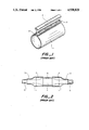
- FIGS. 1 and 2 show prior art techniques for forming cable splice cases
- FIG. 3 shows a wrap-around sleeve having a sealing strip for securing it in the wrapped configuration
- FIG. 4 shows a strip of FIG. 3 when installed
- FIG. 5 shows a sealing strip with electrical heating means
- FIG. 6 shows a sealing strip and sheet edge portions with matching profiles
- FIG. 7 shows a thin and flexible heating strip of substantially rectangular cross-section, together with electrodes
- FIG. 8 shows in cross-section a preferred heating strip of the general type shown in FIG. 7;
- FIGS. 9-11 show preferred uses of the heating strips of the FIGS. 7-8.
- FIG. 1 shows a prior art wrap-around heat-shrinkable sleeve 1, such as that disclosed in GB No. 1,155,470 to Raychem. It comprises a web portion having rails 2 running along opposing longitudinal edge portions. The rails may be held together by a channel 3, that may be slid over them. The sleeve is wrapped around a cable or other substrate, the channel positioned over the rails, and the sleeve heated to cause it to shrink over the cable. In this way a cable splice case may be formed.
- FIG. 2 A more complex cable splice case is shown in FIG. 2.
- a splice 4 is shown joining two multi-core telecommunications cables 5.
- a generally rigid central tube 6 is positioned over the splice 4, and heat-recoverable wrap-around sleeves 1 are installed to provide a seal between each end portion 7 of the tube 6 and the cables 5.
- FIG. 3 illustrates an embodiment of the invention that is able to solve this and other problems.
- a wrap-around sleeve 8 having two plain edge portions 9 may be formed into a tubular structure by use of a sealing strip 10.
- the sealing strip 10 has edge recesses 11 into which the edge portions 9 may be received.
- the sealing strip may be, for example from 1-10, especially 1-5, particularly 2-4 cm wide, and 0.5-3 cm thick, although its precise size will of course depend on the size of the sleeve 8.
- FIG. 4 shows the edge portions inserted into the recesses 11. They may be inserted by sliding the strip 11 longitudinally with respect to the sleeve, or they may be inserted transversely.
- the sealing strip may be heated in any suitable way, for example by torch or by hot-air, but electrical heating is preferred. Preferably heating is substantially localized in region 12, and it preferably causes edges of the edge portion 9 to become welded to it. If preferred, an adhesive may be provided that is activated on heating.
- some means is provided for holding the edge portions in the recesses 11 and against the portion 12, preferably under resilient bias.
- Such means may comprise some wrap such as an elastomeric band, for example a silicone, positioned around the circumference of the sleeve.
- the strip is of such a material that it expands significantly on heating.
- the portion 12 expands thus improving a weld or bond at that region.
- the material of the sealing strip and that of the edge portions 9 are preferably mutually compatible, such that some molecular mixing or interpenetration occurs under heating and preferably pressure.
- the sealing strip preferably comprises ultra high molecular weight polyethylene together with a conductive filler such as carbon black.
- the material is preferably sintered.
- Electrodes 13 are provided attached to, preferably housed within, the strip.
- FIG. 6 shows a sealing strip having a shape in cross-section that corresponds with the shape of the edge portions of the sleeve.
- Protrusion 14 engages recess 16 in the example at the left-hand side
- protrusion 26 engages recess 15 in the example at the right-hand side.
- the edge portions may be a snap fit, or longitudinal sliding may be required. Alternatively, they may be sized such that they are a free fit, and engagement and bonding or welding occur due to thermal expansion (or recovery) on heating.
- the strip may deform on contraction or cooling such that the bond or weld is not put under significant stress.
- the edge portions of the sleeve, although shaped, are substantially plain compared to the profiles of the prior art as shown in FIG. 1.
- the sealing strip may be of low profile, flexible, and require little power. Heating is preferably localized, due to the electrode configuration, and the material of the strip is preferably of low thermal conductivity. Thermal expansion of at least a portion of the strip can ensure that the bond line is put in compression during the heating step.
- FIGS. 7-11 illustrate an inventive heating strip that may, but need not be used with the sealing strip described above.
- FIG. 7 shows a heating strip comprising a resistive heating material, preferably comprising a conductive polymer, particularly ultra high molecular weight polyethylene together with a conductive filler for example carbon black.
- the material is preferably a sintered material.
- the preferred materials given above for the sealing strip apply also to this heating strip.
- the heating strip preferably has a sealing (welding or bonding) function in addition to heating, although it may heat another material and that other material form a bond or weld.
- the heating strip preferably expands on heating to aid bonding or welding.
- a surface temperature of at least 100° C., preferably at least 150° C., especially at least 180° C. is achieved.
- Heating time to these temperatures is preferably less than 5 minutes, more preferably less than 3 minutes, especially less than 1.5 minutes.
- Heat output is preferably 2-30, more preferably 5-20, especially 7-15 watts per square inch. Output may depend on absolute size and these figures may be regarded as typical for a strip in the form of a 0.5 inch wide tape. In general the tape is preferably 0.2 to 2 inches.
- the tape is preferably sufficiently thin that it may be highly flexible, and preferred thicknesses are less than 0.3, more preferably less than 0.2, especially less than 0.15 inch.
- Power may be supplied by electrodes positioned on one or both surfaces as shown in FIG. 7.
- the electrodes preferably extend along the length of the strip, and preferably comprise a metal strip, or foil, such as copper.
- the strip may be coated on one or both sides with a material for the purpose of electrical insulation and/or provision of a sealing material, for example polyethylene.
- FIG. 8 shows in cross-section a heating strip 17, electrodes 18 and a surrounding covering of polyethylene etc.
- FIG. 9 One use of the heating strip is shown in FIG. 9. Here it is used for heating and welding inside the recesses of a sealing strip 10. This allows the sealing strip 10 to be made from a wider range of materials than is the case when strip 10 is itself electrically heatable. For example, strip 10 could be made from unfilled UHMWPE. This avoids the need for difficult shaping operations which would be required particularly for non-melt processable materials.
- FIG. 10 shows a strip 17 used as a wrapping around a cable or pipe.
- FIG. 11 shows various uses for heating strip 17.
- the figure illustrates a splice case 18 comprising half-shells surrounding cables 5.
- Cable jacket repair is shown at 19 as a simple wrap of the tape.
- a seal between a cable (or pipe) and a duct is shown at 20.
- a seal between a cable and a splice case end plate is shown at 21, and a seal between end plate halves is shown at 22.
- a longitudinal seal between the half-shells is shown at 23.
- a seal between a cable and an end cap is shown at 24.
- the heating strip may conveniently be made by skiving or pairing a thin layer from a thicker piece of material.
Abstract
Description
Claims (11)
Priority Applications (1)
| Application Number | Priority Date | Filing Date | Title |
|---|---|---|---|
| US07/394,288 US4938820A (en) | 1987-06-11 | 1989-08-15 | Joining of sheets |
Applications Claiming Priority (2)
| Application Number | Priority Date | Filing Date | Title |
|---|---|---|---|
| US6135487A | 1987-06-11 | 1987-06-11 | |
| US07/394,288 US4938820A (en) | 1987-06-11 | 1989-08-15 | Joining of sheets |
Related Parent Applications (1)
| Application Number | Title | Priority Date | Filing Date |
|---|---|---|---|
| US6135487A Continuation | 1987-02-24 | 1987-06-11 |
Publications (1)
| Publication Number | Publication Date |
|---|---|
| US4938820A true US4938820A (en) | 1990-07-03 |
Family
ID=26740980
Family Applications (1)
| Application Number | Title | Priority Date | Filing Date |
|---|---|---|---|
| US07/394,288 Expired - Fee Related US4938820A (en) | 1987-06-11 | 1989-08-15 | Joining of sheets |
Country Status (1)
| Country | Link |
|---|---|
| US (1) | US4938820A (en) |
Cited By (14)
| Publication number | Priority date | Publication date | Assignee | Title |
|---|---|---|---|---|
| US5111025A (en) * | 1990-02-09 | 1992-05-05 | Raychem Corporation | Seat heater |
| US5145628A (en) * | 1989-12-29 | 1992-09-08 | Rudolph Karg | Process for manufacturing a hose clad with ultra-high molecular weight polyethylene |
| US5312668A (en) * | 1992-09-08 | 1994-05-17 | Brown Kirk D | Paper splice member |
| US5433805A (en) * | 1993-01-12 | 1995-07-18 | Schmidmeier; Alexander | Method for crack prevention in bamboo canes |
| GB2273679B (en) * | 1992-12-23 | 1997-04-23 | Michael Charles Short | Jointing plastics materials |
| GB2308092A (en) * | 1995-12-14 | 1997-06-18 | Toa Kokyu Tugitevarubu Seizo C | Welding plastics sheets |
| US5698056A (en) * | 1995-02-13 | 1997-12-16 | Yokoshima & Company | Method for manufacturing a tubular liner bag |
| US5743989A (en) * | 1995-11-08 | 1998-04-28 | Toua Kokyu Tugitevarubu Seizo Co., Ltd. | Method of welding plastics sheets together and a joint used therein |
| ES2133039A1 (en) * | 1996-03-01 | 1999-08-16 | Toa Kokyu Tugitevarubu Seizo C | Method for welding sheets of plastic together and joint used therein |
| US6245174B1 (en) | 1995-05-31 | 2001-06-12 | Johannes Maria Cordia | Heat recoverable article |
| US10669835B2 (en) * | 2015-11-18 | 2020-06-02 | Halliburton Energy Services, Inc. | Clampless cable protector and installation system |
| CN111390430A (en) * | 2020-03-20 | 2020-07-10 | 青岛正爱科技有限公司 | Preparation method and application of ultra-high molecular weight polyethylene welding wire |
| US20200243216A1 (en) * | 2017-10-13 | 2020-07-30 | Sumitomo Wiring Systems, Ltd. | Wire harness |
| US11174748B2 (en) * | 2015-08-25 | 2021-11-16 | Safran Aircraft Engines | Ring-shaped thermomechanical part for turbine engine |
Citations (63)
| Publication number | Priority date | Publication date | Assignee | Title |
|---|---|---|---|---|
| US2282832A (en) * | 1939-11-24 | 1942-05-12 | Gen Electric | Semiconducting tape |
| US2388297A (en) * | 1941-07-10 | 1945-11-06 | Extruded Plastics Inc | Composite article, including extruded sections |
| US2739829A (en) * | 1950-08-05 | 1956-03-27 | American Viscose Corp | Plastic pipe joint |
| US2930634A (en) * | 1957-02-21 | 1960-03-29 | Coast Mfg And Supply Co | Coupler and method of joining conduits |
| GB839743A (en) * | 1955-07-02 | 1960-06-29 | Evered & Co Ltd | Improvements in or relating to pipe joints |
| US2992457A (en) * | 1960-03-28 | 1961-07-18 | Grace W R & Co | Method of joining pipe and tubing |
| US3049465A (en) * | 1957-11-04 | 1962-08-14 | Phillips Petroleum Co | Method for joining plastic articles |
| FR1374690A (en) * | 1962-11-08 | 1964-10-09 | Dynamit Nobel Ag | Profiles and molding elements incorporating heating conductors |
| GB1010197A (en) * | 1963-07-23 | 1965-11-17 | Cabot Carbon Ltd | Electrically conductive plastics compositions |
| US3340328A (en) * | 1962-12-13 | 1967-09-05 | Continental Oil Co | Blends of polyethylenes having improved properties |
| US3359524A (en) * | 1963-11-11 | 1967-12-19 | Ioco Ltd | Flexible heating elements |
| US3406055A (en) * | 1965-05-20 | 1968-10-15 | Cabot Corp | Welding method for cured polymeric compositions |
| GB1155470A (en) * | 1965-11-03 | 1969-06-18 | Raychem Corp | Heat-recoverable Closure Member and a process for its manufacture |
| US3506519A (en) * | 1967-01-13 | 1970-04-14 | Susquehanna Corp | Method of making interlocked welded connections between thermoplastic articles |
| US3528867A (en) * | 1966-08-15 | 1970-09-15 | Heller William C Jun | Method for selective heat sealing or joining of materials |
| US3542402A (en) * | 1969-04-02 | 1970-11-24 | Catalyst Research Corp | Joining articles of thermoplastic resins |
| FR2111818A1 (en) * | 1970-10-26 | 1972-06-09 | Mannesmann Ag | |
| US3706176A (en) * | 1971-03-10 | 1972-12-19 | Alfred F Leatherman | Closure member and method for closing containers |
| US3891490A (en) * | 1974-06-06 | 1975-06-24 | Raychem Corp | Welded polymeric articles and process |
| US3927233A (en) * | 1974-01-25 | 1975-12-16 | Raychem Corp | Welded polymeric articles and process |
| JPS5184866A (en) * | 1975-01-21 | 1976-07-24 | Daiko Kk | |
| US3987276A (en) * | 1974-05-10 | 1976-10-19 | Georg Fischer Aktiengesellschaft | Welded plastic attachment subassembly |
| US3991243A (en) * | 1974-12-09 | 1976-11-09 | Raychem Corporation | Method of making a reinforced insert weld and resulting article |
| US4025600A (en) * | 1975-05-06 | 1977-05-24 | Bicc Limited | Jointing or terminating plastics sheathed electric cables |
| US4051454A (en) * | 1973-02-16 | 1977-09-27 | Wacker-Chemie Gmbh | Adhesive compositions and flexible heating device fabricated therewith |
| US4055615A (en) * | 1973-09-21 | 1977-10-25 | Yasuo Ikeda | Method of manufacturing electric resistors |
| US4067765A (en) * | 1976-09-17 | 1978-01-10 | William C. Heller, Jr. | Susceptor based bonding technique for plastic material utilizing oleaginous substance at the bonding interface |
| US4085286A (en) * | 1974-09-27 | 1978-04-18 | Raychem Corporation | Heat-recoverable sealing article with self-contained heating means and method of sealing a splice therewith |
| US4090899A (en) * | 1974-12-06 | 1978-05-23 | Georg Fischer A.G. | Thermoplastics welding method |
| US4110145A (en) * | 1976-06-21 | 1978-08-29 | Barney Knitting Machinery Co., Inc. | Method for sealing plastic films and the like |
| JPS53147732A (en) * | 1977-05-28 | 1978-12-22 | Raion Akuzo Kk | Adhesive method and effective heat sensitive adhesives therefor |
| US4151364A (en) * | 1976-09-29 | 1979-04-24 | Ellis J Scott | Electrical connectors and methods of connecting electrical conductors |
| US4151126A (en) * | 1977-04-25 | 1979-04-24 | E. I. Du Pont De Nemours And Company | Polyolefin/conductive carbon composites |
| US4177376A (en) * | 1974-09-27 | 1979-12-04 | Raychem Corporation | Layered self-regulating heating article |
| US4177446A (en) * | 1975-12-08 | 1979-12-04 | Raychem Corporation | Heating elements comprising conductive polymers capable of dimensional change |
| GB2065430A (en) * | 1979-12-13 | 1981-06-24 | Junkosha Co Ltd | A tubular heating device |
| EP0036963A1 (en) * | 1980-03-31 | 1981-10-07 | Georg Fischer Aktiengesellschaft | Welding socket for thermoplastic materials, method and apparatus for its manufacture |
| JPS56161115A (en) * | 1980-05-19 | 1981-12-11 | Bridgestone Corp | Electroconductive fuse welding method |
| GB1605005A (en) * | 1978-05-28 | 1981-12-16 | Raychem Ltd | Electrical heating strip |
| US4330703A (en) * | 1975-08-04 | 1982-05-18 | Raychem Corporation | Layered self-regulating heating article |
| US4330704A (en) * | 1980-08-08 | 1982-05-18 | Raychem Corporation | Electrical devices comprising conductive polymers |
| US4378323A (en) * | 1977-08-26 | 1983-03-29 | Akzona Incorporated | Method of producing plastic collar integral with a cable jacket |
| JPS58164627A (en) * | 1982-03-24 | 1983-09-29 | Mitsuboshi Belting Ltd | Production of electroconductive ultrahigh-molecular polyethylene sinter |
| US4421582A (en) * | 1975-08-04 | 1983-12-20 | Raychem Corporation | Self-heating article with deformable electrodes |
| US4455482A (en) * | 1981-07-01 | 1984-06-19 | Innovation Technique | Heating assembly for heating an area of a thermoplastic pipe |
| EP0117762A1 (en) * | 1983-03-01 | 1984-09-05 | N.V. Raychem S.A. | Electrically heat-recoverable article |
| EP0123540A2 (en) * | 1983-04-20 | 1984-10-31 | RAYCHEM CORPORATION (a California corporation) | Conductive polymers and devices containing them |
| US4502929A (en) * | 1981-06-12 | 1985-03-05 | Raychem Corporation | Corrosion protection method |
| US4518552A (en) * | 1983-11-09 | 1985-05-21 | Mitsuboshi Belting Ltd. | Method of producing accurately sized material of ultra high molecular weight polyethylene |
| EP0157640A2 (en) * | 1984-04-04 | 1985-10-09 | RAYCHEM CORPORATION (a Delaware corporation) | Heat recoverable articles comprising conductive polymer compositions |
| US4548662A (en) * | 1983-05-11 | 1985-10-22 | Raychem Corporation | Method of providing a protective covering over a substrate |
| US4570055A (en) * | 1984-05-07 | 1986-02-11 | Raychem Corporation | Electrically heat-recoverable assembly |
| EP0171450A1 (en) * | 1984-08-14 | 1986-02-19 | Österreichische Salen-Kunststoffwerk Gesellschaft m.b.H. | Connection for plastic pipes and method of manufacture |
| US4575617A (en) * | 1984-04-12 | 1986-03-11 | Cooperheat | Heat tracing tape and power control system |
| JPS61213126A (en) * | 1985-03-18 | 1986-09-22 | Seiji Kawasaki | Welding method for plurality of synthetic resin molded material |
| US4624487A (en) * | 1984-08-08 | 1986-11-25 | Georg Fischer Aktiengesellschaft | Molded tapping fitting for connecting a branch line to a pipeline |
| JPS6248747A (en) * | 1985-08-26 | 1987-03-03 | Mitsuboshi Belting Ltd | Ultra-high-molecular-weight-polyethylene resin composition suitable for ram extrusion molding |
| US4659912A (en) * | 1984-06-21 | 1987-04-21 | Metcal, Inc. | Thin, flexible, autoregulating strap heater |
| US4670078A (en) * | 1983-02-04 | 1987-06-02 | Georg Fischer Aktiengesellschaft | Process for heat-sealing thermoplastic conduits |
| US4695335A (en) * | 1985-11-08 | 1987-09-22 | R. W. Lyall & Company, Inc. | Method for developing a predetermined fusing temperature in thermoplastic items |
| JPS62288029A (en) * | 1986-06-06 | 1987-12-14 | Aisin Seiki Co Ltd | Vessel made of resin and bonded by fusion, and fusion bonding thereof |
| US4729809A (en) * | 1985-03-14 | 1988-03-08 | Amp Incorporated | Anisotropically conductive adhesive composition |
| US4731199A (en) * | 1983-11-09 | 1988-03-15 | Mitsuboshi Belting Ltd. | Ultra high molecular weight concurrently sintered and cross-linked polyethylene product |
-
1989
- 1989-08-15 US US07/394,288 patent/US4938820A/en not_active Expired - Fee Related
Patent Citations (64)
| Publication number | Priority date | Publication date | Assignee | Title |
|---|---|---|---|---|
| US2282832A (en) * | 1939-11-24 | 1942-05-12 | Gen Electric | Semiconducting tape |
| US2388297A (en) * | 1941-07-10 | 1945-11-06 | Extruded Plastics Inc | Composite article, including extruded sections |
| US2739829A (en) * | 1950-08-05 | 1956-03-27 | American Viscose Corp | Plastic pipe joint |
| GB839743A (en) * | 1955-07-02 | 1960-06-29 | Evered & Co Ltd | Improvements in or relating to pipe joints |
| US2930634A (en) * | 1957-02-21 | 1960-03-29 | Coast Mfg And Supply Co | Coupler and method of joining conduits |
| US3049465A (en) * | 1957-11-04 | 1962-08-14 | Phillips Petroleum Co | Method for joining plastic articles |
| US2992457A (en) * | 1960-03-28 | 1961-07-18 | Grace W R & Co | Method of joining pipe and tubing |
| FR1374690A (en) * | 1962-11-08 | 1964-10-09 | Dynamit Nobel Ag | Profiles and molding elements incorporating heating conductors |
| US3340328A (en) * | 1962-12-13 | 1967-09-05 | Continental Oil Co | Blends of polyethylenes having improved properties |
| GB1010197A (en) * | 1963-07-23 | 1965-11-17 | Cabot Carbon Ltd | Electrically conductive plastics compositions |
| US3359524A (en) * | 1963-11-11 | 1967-12-19 | Ioco Ltd | Flexible heating elements |
| US3406055A (en) * | 1965-05-20 | 1968-10-15 | Cabot Corp | Welding method for cured polymeric compositions |
| GB1155470A (en) * | 1965-11-03 | 1969-06-18 | Raychem Corp | Heat-recoverable Closure Member and a process for its manufacture |
| US3528867A (en) * | 1966-08-15 | 1970-09-15 | Heller William C Jun | Method for selective heat sealing or joining of materials |
| US3506519A (en) * | 1967-01-13 | 1970-04-14 | Susquehanna Corp | Method of making interlocked welded connections between thermoplastic articles |
| US3542402A (en) * | 1969-04-02 | 1970-11-24 | Catalyst Research Corp | Joining articles of thermoplastic resins |
| FR2111818A1 (en) * | 1970-10-26 | 1972-06-09 | Mannesmann Ag | |
| US3706176A (en) * | 1971-03-10 | 1972-12-19 | Alfred F Leatherman | Closure member and method for closing containers |
| US4051454A (en) * | 1973-02-16 | 1977-09-27 | Wacker-Chemie Gmbh | Adhesive compositions and flexible heating device fabricated therewith |
| US4055615A (en) * | 1973-09-21 | 1977-10-25 | Yasuo Ikeda | Method of manufacturing electric resistors |
| US3927233A (en) * | 1974-01-25 | 1975-12-16 | Raychem Corp | Welded polymeric articles and process |
| US3987276A (en) * | 1974-05-10 | 1976-10-19 | Georg Fischer Aktiengesellschaft | Welded plastic attachment subassembly |
| US3891490A (en) * | 1974-06-06 | 1975-06-24 | Raychem Corp | Welded polymeric articles and process |
| US4085286A (en) * | 1974-09-27 | 1978-04-18 | Raychem Corporation | Heat-recoverable sealing article with self-contained heating means and method of sealing a splice therewith |
| US4177376A (en) * | 1974-09-27 | 1979-12-04 | Raychem Corporation | Layered self-regulating heating article |
| US4090899A (en) * | 1974-12-06 | 1978-05-23 | Georg Fischer A.G. | Thermoplastics welding method |
| US3991243A (en) * | 1974-12-09 | 1976-11-09 | Raychem Corporation | Method of making a reinforced insert weld and resulting article |
| JPS5184866A (en) * | 1975-01-21 | 1976-07-24 | Daiko Kk | |
| US4025600A (en) * | 1975-05-06 | 1977-05-24 | Bicc Limited | Jointing or terminating plastics sheathed electric cables |
| US4421582A (en) * | 1975-08-04 | 1983-12-20 | Raychem Corporation | Self-heating article with deformable electrodes |
| US4330703A (en) * | 1975-08-04 | 1982-05-18 | Raychem Corporation | Layered self-regulating heating article |
| US4177446A (en) * | 1975-12-08 | 1979-12-04 | Raychem Corporation | Heating elements comprising conductive polymers capable of dimensional change |
| US4110145A (en) * | 1976-06-21 | 1978-08-29 | Barney Knitting Machinery Co., Inc. | Method for sealing plastic films and the like |
| US4067765A (en) * | 1976-09-17 | 1978-01-10 | William C. Heller, Jr. | Susceptor based bonding technique for plastic material utilizing oleaginous substance at the bonding interface |
| US4151364A (en) * | 1976-09-29 | 1979-04-24 | Ellis J Scott | Electrical connectors and methods of connecting electrical conductors |
| US4151126A (en) * | 1977-04-25 | 1979-04-24 | E. I. Du Pont De Nemours And Company | Polyolefin/conductive carbon composites |
| JPS53147732A (en) * | 1977-05-28 | 1978-12-22 | Raion Akuzo Kk | Adhesive method and effective heat sensitive adhesives therefor |
| US4378323A (en) * | 1977-08-26 | 1983-03-29 | Akzona Incorporated | Method of producing plastic collar integral with a cable jacket |
| GB1605005A (en) * | 1978-05-28 | 1981-12-16 | Raychem Ltd | Electrical heating strip |
| GB2065430A (en) * | 1979-12-13 | 1981-06-24 | Junkosha Co Ltd | A tubular heating device |
| EP0036963A1 (en) * | 1980-03-31 | 1981-10-07 | Georg Fischer Aktiengesellschaft | Welding socket for thermoplastic materials, method and apparatus for its manufacture |
| JPS56161115A (en) * | 1980-05-19 | 1981-12-11 | Bridgestone Corp | Electroconductive fuse welding method |
| US4330704A (en) * | 1980-08-08 | 1982-05-18 | Raychem Corporation | Electrical devices comprising conductive polymers |
| US4502929A (en) * | 1981-06-12 | 1985-03-05 | Raychem Corporation | Corrosion protection method |
| US4455482A (en) * | 1981-07-01 | 1984-06-19 | Innovation Technique | Heating assembly for heating an area of a thermoplastic pipe |
| JPS58164627A (en) * | 1982-03-24 | 1983-09-29 | Mitsuboshi Belting Ltd | Production of electroconductive ultrahigh-molecular polyethylene sinter |
| US4670078A (en) * | 1983-02-04 | 1987-06-02 | Georg Fischer Aktiengesellschaft | Process for heat-sealing thermoplastic conduits |
| EP0117762A1 (en) * | 1983-03-01 | 1984-09-05 | N.V. Raychem S.A. | Electrically heat-recoverable article |
| US4675512A (en) * | 1983-03-01 | 1987-06-23 | Nv Raychem Sa | Electrically heat-recoverable article |
| EP0123540A2 (en) * | 1983-04-20 | 1984-10-31 | RAYCHEM CORPORATION (a California corporation) | Conductive polymers and devices containing them |
| US4548662A (en) * | 1983-05-11 | 1985-10-22 | Raychem Corporation | Method of providing a protective covering over a substrate |
| US4518552A (en) * | 1983-11-09 | 1985-05-21 | Mitsuboshi Belting Ltd. | Method of producing accurately sized material of ultra high molecular weight polyethylene |
| US4731199A (en) * | 1983-11-09 | 1988-03-15 | Mitsuboshi Belting Ltd. | Ultra high molecular weight concurrently sintered and cross-linked polyethylene product |
| EP0157640A2 (en) * | 1984-04-04 | 1985-10-09 | RAYCHEM CORPORATION (a Delaware corporation) | Heat recoverable articles comprising conductive polymer compositions |
| US4575617A (en) * | 1984-04-12 | 1986-03-11 | Cooperheat | Heat tracing tape and power control system |
| US4570055A (en) * | 1984-05-07 | 1986-02-11 | Raychem Corporation | Electrically heat-recoverable assembly |
| US4659912A (en) * | 1984-06-21 | 1987-04-21 | Metcal, Inc. | Thin, flexible, autoregulating strap heater |
| US4624487A (en) * | 1984-08-08 | 1986-11-25 | Georg Fischer Aktiengesellschaft | Molded tapping fitting for connecting a branch line to a pipeline |
| EP0171450A1 (en) * | 1984-08-14 | 1986-02-19 | Österreichische Salen-Kunststoffwerk Gesellschaft m.b.H. | Connection for plastic pipes and method of manufacture |
| US4729809A (en) * | 1985-03-14 | 1988-03-08 | Amp Incorporated | Anisotropically conductive adhesive composition |
| JPS61213126A (en) * | 1985-03-18 | 1986-09-22 | Seiji Kawasaki | Welding method for plurality of synthetic resin molded material |
| JPS6248747A (en) * | 1985-08-26 | 1987-03-03 | Mitsuboshi Belting Ltd | Ultra-high-molecular-weight-polyethylene resin composition suitable for ram extrusion molding |
| US4695335A (en) * | 1985-11-08 | 1987-09-22 | R. W. Lyall & Company, Inc. | Method for developing a predetermined fusing temperature in thermoplastic items |
| JPS62288029A (en) * | 1986-06-06 | 1987-12-14 | Aisin Seiki Co Ltd | Vessel made of resin and bonded by fusion, and fusion bonding thereof |
Non-Patent Citations (2)
| Title |
|---|
| Coughlan et al., "Ultrahigh Molecular Weight Polyethylene", Encylopedia Polymer Science and Engineering, 2d, vol. 6, pp. 490-494 (1986). |
| Coughlan et al., Ultrahigh Molecular Weight Polyethylene , Encylopedia Polymer Science and Engineering, 2d, vol. 6, pp. 490 494 (1986). * |
Cited By (16)
| Publication number | Priority date | Publication date | Assignee | Title |
|---|---|---|---|---|
| US5145628A (en) * | 1989-12-29 | 1992-09-08 | Rudolph Karg | Process for manufacturing a hose clad with ultra-high molecular weight polyethylene |
| US5111025A (en) * | 1990-02-09 | 1992-05-05 | Raychem Corporation | Seat heater |
| US5312668A (en) * | 1992-09-08 | 1994-05-17 | Brown Kirk D | Paper splice member |
| GB2273679B (en) * | 1992-12-23 | 1997-04-23 | Michael Charles Short | Jointing plastics materials |
| US5433805A (en) * | 1993-01-12 | 1995-07-18 | Schmidmeier; Alexander | Method for crack prevention in bamboo canes |
| US5698056A (en) * | 1995-02-13 | 1997-12-16 | Yokoshima & Company | Method for manufacturing a tubular liner bag |
| US6245174B1 (en) | 1995-05-31 | 2001-06-12 | Johannes Maria Cordia | Heat recoverable article |
| US5743989A (en) * | 1995-11-08 | 1998-04-28 | Toua Kokyu Tugitevarubu Seizo Co., Ltd. | Method of welding plastics sheets together and a joint used therein |
| GB2308092A (en) * | 1995-12-14 | 1997-06-18 | Toa Kokyu Tugitevarubu Seizo C | Welding plastics sheets |
| GB2308092B (en) * | 1995-12-14 | 2000-03-22 | Toa Kokyu Tugitevarubu Seizo C | Method of welding plastics sheets together and a joint used therein |
| ES2133039A1 (en) * | 1996-03-01 | 1999-08-16 | Toa Kokyu Tugitevarubu Seizo C | Method for welding sheets of plastic together and joint used therein |
| US11174748B2 (en) * | 2015-08-25 | 2021-11-16 | Safran Aircraft Engines | Ring-shaped thermomechanical part for turbine engine |
| US10669835B2 (en) * | 2015-11-18 | 2020-06-02 | Halliburton Energy Services, Inc. | Clampless cable protector and installation system |
| US20200243216A1 (en) * | 2017-10-13 | 2020-07-30 | Sumitomo Wiring Systems, Ltd. | Wire harness |
| US10937565B2 (en) * | 2017-10-13 | 2021-03-02 | Sumitomo Wiring Systems, Ltd. | Wire harness |
| CN111390430A (en) * | 2020-03-20 | 2020-07-10 | 青岛正爱科技有限公司 | Preparation method and application of ultra-high molecular weight polyethylene welding wire |
Similar Documents
| Publication | Publication Date | Title |
|---|---|---|
| US4085286A (en) | Heat-recoverable sealing article with self-contained heating means and method of sealing a splice therewith | |
| US4938820A (en) | Joining of sheets | |
| FI64482B (en) | VAERMEAOTERHAEMTBAR ANORDNING OCH ANORDNING AV DENSAMMA FOER EN KABELSKARV | |
| US5286952A (en) | Methods and devices which make use of conductive polymers to join articles | |
| US5302428A (en) | Multi-layer wraparound heat shrink sleeve | |
| EP0245067B1 (en) | Heat recoverable article | |
| JPS59226613A (en) | Electric heat recovering article | |
| JP2582886B2 (en) | Article joining method | |
| CA1321698C (en) | Heat recoverable article | |
| US5117094A (en) | Heat recoverable article | |
| EP0196767B1 (en) | Pressurizable splice case | |
| EP0433368B1 (en) | Method of cable sealing | |
| US4880962A (en) | Electrical device | |
| US5451278A (en) | Environmental protection | |
| US5013894A (en) | Conductive polymeric article | |
| US5560847A (en) | Environmental protection of a pipe by means of a conductive polymer sheet | |
| JP2622421B2 (en) | Method and apparatus for joining articles using conductive polymers | |
| EP0307199B1 (en) | Heat recoverable article | |
| US4990379A (en) | Heat recoverable article | |
| CA2114288C (en) | Multi-layer wraparound heat shrink sleeve | |
| FI68933C (en) | FOERFARANDE FOER ATT FOERSLUTA EN SKARV MELLAN TVAO ELLER FLERE KABLAR ELLER ROER SAMT VAERMEREGENERERBART FOERSLUTNINGSELEMENT FOER UTFOERANDE AV FOERFARANDET | |
| TW264583B (en) | Sealing structure of heat-shrinkable sleeve for junction of pipes or cables |
Legal Events
| Date | Code | Title | Description |
|---|---|---|---|
| FPAY | Fee payment |
Year of fee payment: 4 |
|
| FEPP | Fee payment procedure |
Free format text: PAT HOLDER CLAIMS SMALL ENTITY STATUS - SMALL BUSINESS (ORIGINAL EVENT CODE: SM02); ENTITY STATUS OF PATENT OWNER: SMALL ENTITY |
|
| REMI | Maintenance fee reminder mailed | ||
| AS | Assignment |
Owner name: CENTRAL PLASTICS COMPANY, OKLAHOMA Free format text: ASSIGNMENT OF ASSIGNORS INTEREST;ASSIGNOR:RAYCHEM CORPORATION;REEL/FRAME:009123/0858 Effective date: 19970430 |
|
| FPAY | Fee payment |
Year of fee payment: 8 |
|
| SULP | Surcharge for late payment | ||
| REMI | Maintenance fee reminder mailed | ||
| LAPS | Lapse for failure to pay maintenance fees | ||
| STCH | Information on status: patent discontinuation |
Free format text: PATENT EXPIRED DUE TO NONPAYMENT OF MAINTENANCE FEES UNDER 37 CFR 1.362 |
|
| FP | Lapsed due to failure to pay maintenance fee |
Effective date: 20020703 |