US4941074A - Light boxes - Google Patents
Light boxes Download PDFInfo
- Publication number
- US4941074A US4941074A US07/291,625 US29162588A US4941074A US 4941074 A US4941074 A US 4941074A US 29162588 A US29162588 A US 29162588A US 4941074 A US4941074 A US 4941074A
- Authority
- US
- United States
- Prior art keywords
- light
- box
- ambulance
- interior
- reflecting film
- Prior art date
- Legal status (The legal status is an assumption and is not a legal conclusion. Google has not performed a legal analysis and makes no representation as to the accuracy of the status listed.)
- Expired - Fee Related
Links
Images


Classifications
-
- B—PERFORMING OPERATIONS; TRANSPORTING
- B60—VEHICLES IN GENERAL
- B60Q—ARRANGEMENT OF SIGNALLING OR LIGHTING DEVICES, THE MOUNTING OR SUPPORTING THEREOF OR CIRCUITS THEREFOR, FOR VEHICLES IN GENERAL
- B60Q1/00—Arrangement of optical signalling or lighting devices, the mounting or supporting thereof or circuits therefor
- B60Q1/26—Arrangement of optical signalling or lighting devices, the mounting or supporting thereof or circuits therefor the devices being primarily intended to indicate the vehicle, or parts thereof, or to give signals, to other traffic
-
- B—PERFORMING OPERATIONS; TRANSPORTING
- B60—VEHICLES IN GENERAL
- B60Q—ARRANGEMENT OF SIGNALLING OR LIGHTING DEVICES, THE MOUNTING OR SUPPORTING THEREOF OR CIRCUITS THEREFOR, FOR VEHICLES IN GENERAL
- B60Q3/00—Arrangement of lighting devices for vehicle interiors; Lighting devices specially adapted for vehicle interiors
- B60Q3/30—Arrangement of lighting devices for vehicle interiors; Lighting devices specially adapted for vehicle interiors for compartments other than passenger or driving compartments, e.g. luggage or engine compartments
-
- B—PERFORMING OPERATIONS; TRANSPORTING
- B60—VEHICLES IN GENERAL
- B60Q—ARRANGEMENT OF SIGNALLING OR LIGHTING DEVICES, THE MOUNTING OR SUPPORTING THEREOF OR CIRCUITS THEREFOR, FOR VEHICLES IN GENERAL
- B60Q3/00—Arrangement of lighting devices for vehicle interiors; Lighting devices specially adapted for vehicle interiors
- B60Q3/40—Arrangement of lighting devices for vehicle interiors; Lighting devices specially adapted for vehicle interiors specially adapted for specific vehicle types
- B60Q3/41—Arrangement of lighting devices for vehicle interiors; Lighting devices specially adapted for vehicle interiors specially adapted for specific vehicle types for mass transit vehicles, e.g. buses
- B60Q3/43—General lighting
-
- B—PERFORMING OPERATIONS; TRANSPORTING
- B60—VEHICLES IN GENERAL
- B60Q—ARRANGEMENT OF SIGNALLING OR LIGHTING DEVICES, THE MOUNTING OR SUPPORTING THEREOF OR CIRCUITS THEREFOR, FOR VEHICLES IN GENERAL
- B60Q3/00—Arrangement of lighting devices for vehicle interiors; Lighting devices specially adapted for vehicle interiors
- B60Q3/60—Arrangement of lighting devices for vehicle interiors; Lighting devices specially adapted for vehicle interiors characterised by optical aspects
- B60Q3/62—Arrangement of lighting devices for vehicle interiors; Lighting devices specially adapted for vehicle interiors characterised by optical aspects using light guides
- B60Q3/64—Arrangement of lighting devices for vehicle interiors; Lighting devices specially adapted for vehicle interiors characterised by optical aspects using light guides for a single lighting device
-
- F—MECHANICAL ENGINEERING; LIGHTING; HEATING; WEAPONS; BLASTING
- F21—LIGHTING
- F21S—NON-PORTABLE LIGHTING DEVICES; SYSTEMS THEREOF; VEHICLE LIGHTING DEVICES SPECIALLY ADAPTED FOR VEHICLE EXTERIORS
- F21S2/00—Systems of lighting devices, not provided for in main groups F21S4/00 - F21S10/00 or F21S19/00, e.g. of modular construction
-
- F—MECHANICAL ENGINEERING; LIGHTING; HEATING; WEAPONS; BLASTING
- F21—LIGHTING
- F21S—NON-PORTABLE LIGHTING DEVICES; SYSTEMS THEREOF; VEHICLE LIGHTING DEVICES SPECIALLY ADAPTED FOR VEHICLE EXTERIORS
- F21S8/00—Lighting devices intended for fixed installation
- F21S8/04—Lighting devices intended for fixed installation intended only for mounting on a ceiling or the like overhead structures
-
- F—MECHANICAL ENGINEERING; LIGHTING; HEATING; WEAPONS; BLASTING
- F21—LIGHTING
- F21V—FUNCTIONAL FEATURES OR DETAILS OF LIGHTING DEVICES OR SYSTEMS THEREOF; STRUCTURAL COMBINATIONS OF LIGHTING DEVICES WITH OTHER ARTICLES, NOT OTHERWISE PROVIDED FOR
- F21V7/00—Reflectors for light sources
- F21V7/04—Optical design
- F21V7/05—Optical design plane
-
- Y—GENERAL TAGGING OF NEW TECHNOLOGICAL DEVELOPMENTS; GENERAL TAGGING OF CROSS-SECTIONAL TECHNOLOGIES SPANNING OVER SEVERAL SECTIONS OF THE IPC; TECHNICAL SUBJECTS COVERED BY FORMER USPC CROSS-REFERENCE ART COLLECTIONS [XRACs] AND DIGESTS
- Y10—TECHNICAL SUBJECTS COVERED BY FORMER USPC
- Y10S—TECHNICAL SUBJECTS COVERED BY FORMER USPC CROSS-REFERENCE ART COLLECTIONS [XRACs] AND DIGESTS
- Y10S362/00—Illumination
- Y10S362/804—Surgical or dental spotlight
Definitions
- This invention relates generally to light boxes and, more specifically, to a light box that can be used in an ambulance to provide the necessary illumination for treating patients as they are transported to a hospital.
- the concept of light boxes or light tubes wherein a light source located at one end of an elongated fixture transmits light radially outward along the entire length of the elongated fixture is known in the art.
- One of the difficulties with the use of light boxes as overhead lights in applications as ambulances is that the light boxes generally do not have sufficient, uniform, light output to satisfy minimum Federal lighting requirements for ambulances.
- the present invention is directed to an improved light box that uses high light reflecting films such as prismatic films.
- the use of prismatic films or light guides that have substantially 100% total reflection that are located on the interior of the light guide is discussed in the Paper by Stevan G. Saxe titled Progress in the Development of Prism Light Guides A second paper from 3M Center in St. Paul, Minn.
- 3M Brand Scotchlamp Film that can be used either as a light conduit or as a continuous glowing luminaire.
- a light source is located at one end of a light box with a reflective mirror located at the opposite end.
- the interior of the light box is covered with a conventional white light reflecting material such as white paper or white paint.
- a cylinder of the high light reflecting film that has substantially 100% total internal reflection. This product is sometimes also referred to in the industry as a prismatic film.
- the use of a high light reflecting film that has substantially 100% total internal light reflection in a light source is described by 3M as being analogous to a perforated garden hose that fills up with water under pressure, with the pressure forcing the water out the perforations along the garden hose.
- 3M The use of a high light reflecting film that has substantially 100% total internal light reflection in a light source is described by 3M as being analogous to a perforated garden hose that fills up with water under pressure, with the pressure forcing the water out the perforations along the garden hose.
- a tube of the high light reflective film the light is continually reflected inward however, since even the high light reflective films are not 100% perfect, some light does leak out through the film. It is this light that leaks out through the high light reflective film that provides the illumination to the surrounding area that makes light box useful as a light source.
- the present invention utilizes the existing high light reflective film to produce an improved light output through the arrangement of the high light reflective film and the light reflecting surfaces to provides a low cost light box that provides
- the prior art concept of a light distribution system is shown in the paper entitled 3M Brand Scotchlamp Film which shows a conventional light source on one end of the light guide and a mirror on the opposite end of a light box.
- Located on one side of the light box is a rectangular shaped light diffuser panel that covers one face of the light box to permit light to leak out to the surrounding area.
- the light box includes a rectangular shaped box with an interior cavity which is coated with a conventional light reflecting material such as white paper or white paint.
- Located inside of the rectangular shaped box is an elongated elliptical shaped cylinder of the high light reflective film of the type manufactured and sold by 3M Company.
- the high light reflective film differs from the conventional white surface light reflecting surfaces in that the high light reflective film has substantially 100% total internal light reflection of the light rays whereas the white paper of white painted surface absorbs a substantial amount of the light.
- Such high light reflecting films have been known but have generally been difficult to manfacture until recently.
- the 3M prior art light system uses a cylinder of high light reflective film to act as a cylindrical guide to direct and redirect the light along the entire length of the light box.
- the present invention through arrangement of two light reflective films and conventional light reflecting and absorbing materials such as white paper, provides a brighter, more uniform light output than the use of the high light reflecting film as a continuous interior light guide.
- the U.S. Pat. No. 4,260,220 shows a light guide made from a high light reflective film of dielectric material such as plastic that is formed to provide light reflection by use of a surface that provides substantially total internal reflection.
- the U.S. Pat. No. 4,536,828 shows a free standing lighting device that is used to convey the outside solar light to the darker interiors of a building with the use of a light guide and a light reflecting surface located in the interior of the building.
- the U.S. Pat. No. 4,637,686 shows an optical fiber that uses a light reflecting material to dissipate light leaking out of the cladding layer in the optical fiber.
- the U.S. Pat. No. 4,709,304 shows a light radiator that permits the user to move the source of the light from the optical cable back and forth to supply light rays over a wider area.
- the U.S. Pat. No. 4,737,896 shows an illumination device that converts the light rays into parallel rays and then directs the parallel rays to an object to be illuminated.
- the U.S. Pat. No. 4,748,545 shows an illumination system having a plurality of light sources that are spaced along a reflecting member to thereby direct light over an item on display.
- the U.S. Pat. No. 4,528,617 shows a light distribution apparatus for distributing light from a small source over a larger area through internally reflecting the light waves in an integral diffusor and distributor block.
- the U.S. Pat. No. 4,422,719 shows a flexible light guide comprised of a transparent plastic core with an outer covering of a tube of plastic material that is shrunk fit onto the plastic core.
- the flexible light guide is used to light signs and on articles such as bicycles to provide an illuminated rod that can either convey a message or alert someone to the prescence of a bicycler.
- the U.S. Pat. No. 3,317,722 shows an electroluminescent lamp having a rigid body with a flexible electroluminescent tape extending through a hollow in the rigid body.
- the U.S. Pat. No. 3,583,786 shows an optical wave guide having a hollow glass tube surrounded by pairs of dielectric material and an outer metal coating on the wave guide.
- the optical wave guide permits the user to transmit light from a source to a load through the hollow glass tube.
- the present invention comprises an improved light box that, through arrangement of a high light reflecting film and conventional white background material, provides a light box with a high intensity uniform light output along the entire length of the light box.
- FIG. 1 shows an exploded view of a light box of the present invention
- FIG. 2 shows an ambulance having a plurality of light boxes located in the ceiling panels of the ambulance
- FIG. 3 shows an alternate embodiment of the light box for providing a second source of light
- FIG. 4 shows a sectional view of the end of the light box located in the ceiling of an ambulance.
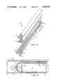
- FIG. 5 shows a bottom view of another embodiment of the light box
- FIG. 6 shows a sectional view of the end of the light box of FIG. 5.
- FIG. 7 shows a sectional view of light boxes located in lengthwise in the body of an ambulance.
- reference numeral 10 identifies the light box of the present invention which is suitable for use in ambulances which require that certain minimum light levels are maintained when the lights are in use.
- An elongated rectangular open shell 11 extends a length of approximately 6 feet to permit the light box to be mounted crosswise along the entire width of the ambulance body.
- a layer of high light reflective film 13 forms a cover to shell 11 and is located directly beneath a conventional outer light diffuser panel 12.
- the high light reflective films are operable to reflect substantially all the light internally and thus maintain as much as possible of the light within the confines of the light box. In the present invention, as in the prior art light boxes, it is the leakage of light through the high light reflective film that is used for illumination of the interior of an ambulance.
- high light reflective film comprises precision micromachined polymer film that produces prismatic facets which reflect the light internally.
- Such high light reflective films are sold by the 3M Company in St. Paul, Minn. and are more fully described in the Whitehead U.S. Pat. No. 4,260,220 titled Prism Light Guide Having Surfaces Which Are In Octature, which is cited in the description of the prior art and included herewith.
- Other types of films that are capable of internally reflecting the light are also usable in the present invention.
- the light diffuser panel 12 comprises a rigid panel of polymer plastic or glass that is conventionally used to diffuse light and provide a more uniform dispersion of light before it is emitted into the surrounding atmosphere. Both the diffuser panels and the high light reflective films are well known in the art and have been used to reflect and diffuse light emanating from a light source.
- a pair of 12 volt fifty watt incandescent light bulbs that are housed in a first hemispherical reflector housing 15 and a second hemispherical reflector housing 16.
- Leads 18 connect the light bulb in reflector housing 16 to the electrical system in the ambulance.
- leads 17 connect the light bulb located in reflector housing 15 to the electrical system of the ambulance.
- Reflective light housings 15 and 16 direct the light from the bulbs located therein through a heat treated glass 33 (see FIG. 3) into the interior of a box that forms an open shell 11.
- a mirror 24 that reflects light back into the interior of shell 11.
- a first rectangular sheet of high light reflective film 12 is located on one side of light box 10 and a second triangular shaped piece of high light reflective film 14 is located on the opposite side of light box 10 and along the bottom of shell 11.
- the interior side 21 and the interior side 23 of shell 11 are covered with a conventional light reflecting surface such as the white paper with an adhesive backing which is sold by Dupont under the name TYVAK.
- the purpose of the white surface is to provide a light reflecting surface that has both light reflecting characteristics and light absorbing surfaces, with the light reflecting characteristics of the surfaces substantially less than the substantial 100% total internal reflection produced by the high light reflecting films.
- the light box of the present invention contains two materials of substantially different light reflecting properties that are directly exposed to the light in the interior of the light box.
- the bottom of shell 11 also contains a sheet of white paper 20 which is secured thereto by an adhesive.
- the purpose of white paper 20 on the bottom of light box 10 and on the sides 21 and 23 is to provide surfaces that both reflect light and absorb light.
- the prior art devices such as the 3M light distribution system have used a white paper background on the interior of the light box with a cylindrical tube of high light reflective film for reflecting the light located within the interior of the light box.
- the use of the combination of the white background material with a continuous cylinder of high light reflective film located in the light box produces substantially less light and less uniform light output than the present invention which uses both conventional light reflecting surfaces and high light reflecting films exposed to the light on the interior of the light box.
- FIG. 2 shows a partial cutaway of an ambulance 50.
- Ambulance 50 includes an ambulance body 53 and a driver's compartment 52.
- Reference numeral 51 identifies the roof or top of ambulance body 53.
- Ambulance body 53 has a series of light boxes 10 located between the ceiling panels 55. Ceiling panels 55 and light boxes 10 are attached to roof 51 through suitable fasteners such as screws or the like.
- the light boxes 10 extend crosswise in the ambulance body 53 to provide a uniform light output in the ambulance body.
- the recess of the light boxes 10 between ceiling panels 55 permits the light boxes to be unobtrusive to a person or persons in the ambulance body 53.
- FIG. 3 there is shown an alternate embodiment of my invention that is identical to the light box of FIG. 1 except that in the mirror surface 41 located on the end of the shell 11 I provide an opening for mounting a blue incandescent light 40. While blue is described, other colored lights could also be used in my invention.
- Light 40 connects to the ambulance lighting system through electrical leads 42.
- the purpose of having a blue light at one end of the light box is for those situations when the interior of the ambulance requires only a soft light of less intensity. For example, sometimes ambulance light shining on the patient who is under the influence of drugs such as crack can trigger adverse reaction from the patient. In these circumstances, the ambulance operator can shut off one or both of the systems that supply power to leads 17 and 18 and power the blue light 40 located on the opposite end of light box 11 thereby converting the light box to a trauma light for transporting a patient in the ambulance.
- Shell 11 attaches to the interior of ambulance top 51 through fasteners such as screw fasteners or the like (not shown).
- an adhesive 35 that secures white paper 20 to the interior of the shell 11.
- high light reflective film 14 and tape 39 that extends onto high light reflective film 14 to hold film 14 in place within shell 11.
- light box 10 On the opposite side of light box 10 is conventional light diffuser panel 12 and high light reflective film 13.
- a piece of heat-tempered glass such as 0.25 inch Pyrex glass across the end of the shell 11 that includes the two 12 volt fifty watt incandescent light bulbs.
- the glass acts as a thermal barrier to help prevent the heat generated by the bulbs out of shell 11 thereby insuring that the light box remains cool to the touch along the portion of the light box that emits light to the interior of the ambulance body.
- the maintaining of the light box in a cool state insures that adhesives used to secure the white paper and the high light reflective film to the interior of the shell do not deteriorate and allow the paper and high light reflective films to slip from their location on the inside of the light box.
- An opaque panel 62 located next to the wall of the ambulance covers the end of shell 11 to hide the wiring 17 and bulb housings.
- FIG. 5 and FIG. 6 there is shown another embodiment of the invention that is suitable for longer runs. That is, the embodiment of FIG. 1 to FIG. 3 provides uniform light output for lengths of approximately six feet. For longer runs that will require the same light output one may use the embodiment of FIG. 5 and FIG. 6.
- the light box 60 shown in FIG. 5 is similar to the light box 10 FIG. 1 except that in light box 60 the high light reflecting film converges to the middle of the light box from the light bulbs located on opposite ends of the light box 60.
- FIG. 5 shows a light box 60 having a metal rectangular shaped housing 61 having an interior surface 62, with upward projecting parallel side walls 63 and 64. Interior surface 62 and side walls 63 and 64 are covered with a conventional white background material such as white paper or white paint. Located on top of interior surface 62 are four separate high light reflecting films 75, 76, 77, and 78 which have been previously described with regard to light box 10. Located on the ends of light box 60 are two sets of lights. On one end of light box 60 there is a light housing 72 and a light housing 74 with each of the housings holding a fifty watt incandescent light bulb.
- Leads 71 connect the incandescent light bulb in housing 72 to the ambulance interior lighting system while the leads 73 connect the incandescent light bulb in housing 74 to the ambulance interior lighting system.
- a high temperature glass 81 such as PYREX and located on adjacent to glass 81 is a light reflecting surface 80 having openings therethrough to permit the light to enter the interior of the light box 60.
- FIG. 6 shows a detail of the opposite end of light box 60 which also has light bulb housings 67 and 69 with incandescent light bulbs located therein and respectively connected to the ambulance lighting system through leads 70 and 68.
- a sheet of high temperature glass 82 covers the light bulb housings to keep the heat generated from the incandescent light bulbs from entering the interior of light box 60.
- Located on the interior end of light box 60 is a light reflecting surface 83 having a first opening 85 to permit the light from the light bulb in housing 69 to enter the interior of light box 60 and a second opening 86 to permit the light from the light bulb located in housing 67 to enter the interior of the light box 60.
- Light reflecting surface 83 and light reflecting surface 80 are typically glass mirrors. Glass 81 and mirror 80 are held in place by side clips 96 and 97 while glass 82 and mirror 83 are held in place by side clips 98 and 99.
- the light box 60 is symmetrical about line 100 extending through the center of light box 60 with identical light housings and associated structure on each end of light box 60.
- FIG. 6 In the embodiment of FIG. 6 which I use in a light fixture having a length of over eight feet I have provided for a slightly different position of the high light reflecting film on the interior surface 62.
- a review of FIG. 6 shows that there are four separate triangularly shaped high light reflecting surfaces 75, 76, 77, and 78 located on the interior surface 62. Each of the high light reflecting surfaces converges as it gets farther away from the light source.
- a single high light reflecting film converges away from two sources of incandescent light while in the light box 60 the high light reflecting film converges away from each of the light sources.
- the high light reflecting films converge only to the center of the light box 60 where they meet with the converging high light reflecting film from the opposite end of light box 60.
- the light box system using light boxes 10 extending crosswise of ambulance FIG.
- I show a cutaway of the rear of an ambulance 90 that is using two light boxes 60 located lengthwise in the ambulance body 91. Located between light boxes 60 are ceiling panels 93 which are identical to the ceiling panels used with light box 10.
- the patient cot area is designated by number 94 and shows that in the typical ambulance the patient cot area lies lengthwise in the ambulance body.
- the light box 60 located directly above and parallel to the patient cot area 94 I provide for the best lighting along the entire length of the patient, which may be useful if the patient has injuries over his or her entire body such as often occurs in an automobile accident.
- the person administrating aid to the victim can stand on floor 95 while the patient's body is bathed in the light emanating from the light box 60, which is directly over the patient and parallel to the patient's body.
Abstract
Description
Claims (14)
Priority Applications (2)
| Application Number | Priority Date | Filing Date | Title |
|---|---|---|---|
| US07/291,625 US4941074A (en) | 1988-12-29 | 1988-12-29 | Light boxes |
| CA000594906A CA1328249C (en) | 1988-12-29 | 1989-03-28 | Light boxes |
Applications Claiming Priority (1)
| Application Number | Priority Date | Filing Date | Title |
|---|---|---|---|
| US07/291,625 US4941074A (en) | 1988-12-29 | 1988-12-29 | Light boxes |
Publications (1)
| Publication Number | Publication Date |
|---|---|
| US4941074A true US4941074A (en) | 1990-07-10 |
Family
ID=23121090
Family Applications (1)
| Application Number | Title | Priority Date | Filing Date |
|---|---|---|---|
| US07/291,625 Expired - Fee Related US4941074A (en) | 1988-12-29 | 1988-12-29 | Light boxes |
Country Status (2)
| Country | Link |
|---|---|
| US (1) | US4941074A (en) |
| CA (1) | CA1328249C (en) |
Cited By (18)
| Publication number | Priority date | Publication date | Assignee | Title |
|---|---|---|---|---|
| US5193899A (en) * | 1989-04-25 | 1993-03-16 | Mitsubishi Rayon Co., Ltd. | Planar light-source device and illumination apparatus using the same |
| US5309544A (en) * | 1992-03-31 | 1994-05-03 | Minnesota Mining And Manufacturing Company | Light pipe having optimized cross-section |
| US5481637A (en) * | 1994-11-02 | 1996-01-02 | The University Of British Columbia | Hollow light guide for diffuse light |
| US5544907A (en) * | 1995-03-31 | 1996-08-13 | Industrial Technology Research Institute | Composite bicycle frame with y shaped tubular configuration |
| US5921670A (en) * | 1996-03-15 | 1999-07-13 | Daimler-Benz Aerospace Airbus Gmbh | Lighting system for a passenger cabin especially in an aircraft |
| US6108965A (en) * | 1998-04-03 | 2000-08-29 | Brandenburg Limited | Trap for catching insects |
| US6116761A (en) * | 1998-05-19 | 2000-09-12 | Munsey; Ronald L. | Illuminating pickup truck bed cover |
| US6443585B1 (en) | 2000-04-25 | 2002-09-03 | Honeywell International Inc. | Hollow cavity light guide for the distribution of collimated light to a liquid crystal display |
| EP1270331A1 (en) * | 2001-06-29 | 2003-01-02 | Teknoware Oy | Arrangement in connection with a lighting fixture, and a lighting fixture |
| US20030046890A1 (en) * | 2001-09-11 | 2003-03-13 | Lynch Diane Irene | Moire ceiling panels |
| US6761475B2 (en) * | 2001-05-18 | 2004-07-13 | C.R.F. Società Consortile Per Azioni | Lighting device, particularly a motor vehicle light or emergency light |
| US20050039361A1 (en) * | 2002-10-08 | 2005-02-24 | Wu Chen H. | Method and apparatus for backlit signs with light emitting diode modules |
| US20060152936A1 (en) * | 2005-01-07 | 2006-07-13 | Bud Thomas | Light assembly for a vehicle |
| US20130039083A1 (en) * | 2011-08-08 | 2013-02-14 | Qing Gong | Logo device for vehicle |
| US20130272005A1 (en) * | 2012-04-13 | 2013-10-17 | Hon Yu Auto Parts Co., Ltd. | Light Emitting Module and Car Threshold Pedal Therewith |
| US20140169026A1 (en) * | 2012-12-15 | 2014-06-19 | Lumenetix, Inc. | Thermal path for heat dissipation in a linear light module |
| EP2779146B1 (en) | 2005-10-11 | 2017-07-26 | Philips Lighting Holding B.V. | Display device |
| US20200170130A1 (en) * | 2014-10-27 | 2020-05-28 | Samsung Electronics Co., Ltd. | Display apparatus |
Citations (12)
| Publication number | Priority date | Publication date | Assignee | Title |
|---|---|---|---|---|
| US3317722A (en) * | 1965-04-26 | 1967-05-02 | Frances L Whitney | Electroluminescent lamp |
| US3583786A (en) * | 1969-09-23 | 1971-06-08 | Bell Telephone Labor Inc | Optical waveguide formed of cylinders with optically smooth interfaces therebetween |
| US4260220A (en) * | 1979-06-15 | 1981-04-07 | Canadian Patents And Development Limited | Prism light guide having surfaces which are in octature |
| US4422719A (en) * | 1981-05-07 | 1983-12-27 | Space-Lyte International, Inc. | Optical distribution system including light guide |
| US4528617A (en) * | 1982-02-08 | 1985-07-09 | Sheltered Workshop For The Disabled, Inc. | Light distribution apparatus |
| US4536828A (en) * | 1980-06-27 | 1985-08-20 | Kei Mori | Lighting device |
| US4637686A (en) * | 1983-04-08 | 1987-01-20 | Kokusai Denshin Denwa Co., Ltd. | Optical fiber with light reflecting particles dispersed through buffer layers to dissipate leaky cladding modes |
| DE3612178A1 (en) * | 1986-04-11 | 1987-10-22 | Binz Gmbh & Co | Device for the illumination of a working area in ambulances |
| US4709304A (en) * | 1984-09-07 | 1987-11-24 | Kei Mori | Light radiator |
| US4737896A (en) * | 1985-07-23 | 1988-04-12 | Canon Kabushiki Kaisha | Illumination device |
| US4748545A (en) * | 1986-02-20 | 1988-05-31 | Reflector Hardware Corporation | Illumination systems |
| US4805984A (en) * | 1985-11-21 | 1989-02-21 | Minnesota Mining And Manufacturing Company | Totally internally reflecting light conduit |
-
1988
- 1988-12-29 US US07/291,625 patent/US4941074A/en not_active Expired - Fee Related
-
1989
- 1989-03-28 CA CA000594906A patent/CA1328249C/en not_active Expired - Fee Related
Patent Citations (12)
| Publication number | Priority date | Publication date | Assignee | Title |
|---|---|---|---|---|
| US3317722A (en) * | 1965-04-26 | 1967-05-02 | Frances L Whitney | Electroluminescent lamp |
| US3583786A (en) * | 1969-09-23 | 1971-06-08 | Bell Telephone Labor Inc | Optical waveguide formed of cylinders with optically smooth interfaces therebetween |
| US4260220A (en) * | 1979-06-15 | 1981-04-07 | Canadian Patents And Development Limited | Prism light guide having surfaces which are in octature |
| US4536828A (en) * | 1980-06-27 | 1985-08-20 | Kei Mori | Lighting device |
| US4422719A (en) * | 1981-05-07 | 1983-12-27 | Space-Lyte International, Inc. | Optical distribution system including light guide |
| US4528617A (en) * | 1982-02-08 | 1985-07-09 | Sheltered Workshop For The Disabled, Inc. | Light distribution apparatus |
| US4637686A (en) * | 1983-04-08 | 1987-01-20 | Kokusai Denshin Denwa Co., Ltd. | Optical fiber with light reflecting particles dispersed through buffer layers to dissipate leaky cladding modes |
| US4709304A (en) * | 1984-09-07 | 1987-11-24 | Kei Mori | Light radiator |
| US4737896A (en) * | 1985-07-23 | 1988-04-12 | Canon Kabushiki Kaisha | Illumination device |
| US4805984A (en) * | 1985-11-21 | 1989-02-21 | Minnesota Mining And Manufacturing Company | Totally internally reflecting light conduit |
| US4748545A (en) * | 1986-02-20 | 1988-05-31 | Reflector Hardware Corporation | Illumination systems |
| DE3612178A1 (en) * | 1986-04-11 | 1987-10-22 | Binz Gmbh & Co | Device for the illumination of a working area in ambulances |
Non-Patent Citations (2)
| Title |
|---|
| Article by 3M Titled "3M Brand Scotchlamp Film" Article Titled Progress in the Development of Prism Light Guides by Steven G. Saxe, Lorne A. Whitehead and Sanford Cobb, Jr. |
| Article by 3M Titled 3M Brand Scotchlamp Film Article Titled Progress in the Development of Prism Light Guides by Steven G. Saxe, Lorne A. Whitehead and Sanford Cobb, Jr. * |
Cited By (24)
| Publication number | Priority date | Publication date | Assignee | Title |
|---|---|---|---|---|
| US5193899A (en) * | 1989-04-25 | 1993-03-16 | Mitsubishi Rayon Co., Ltd. | Planar light-source device and illumination apparatus using the same |
| US5309544A (en) * | 1992-03-31 | 1994-05-03 | Minnesota Mining And Manufacturing Company | Light pipe having optimized cross-section |
| US5481637A (en) * | 1994-11-02 | 1996-01-02 | The University Of British Columbia | Hollow light guide for diffuse light |
| US5544907A (en) * | 1995-03-31 | 1996-08-13 | Industrial Technology Research Institute | Composite bicycle frame with y shaped tubular configuration |
| US5921670A (en) * | 1996-03-15 | 1999-07-13 | Daimler-Benz Aerospace Airbus Gmbh | Lighting system for a passenger cabin especially in an aircraft |
| US6108965A (en) * | 1998-04-03 | 2000-08-29 | Brandenburg Limited | Trap for catching insects |
| US6116761A (en) * | 1998-05-19 | 2000-09-12 | Munsey; Ronald L. | Illuminating pickup truck bed cover |
| US6443585B1 (en) | 2000-04-25 | 2002-09-03 | Honeywell International Inc. | Hollow cavity light guide for the distribution of collimated light to a liquid crystal display |
| US6761475B2 (en) * | 2001-05-18 | 2004-07-13 | C.R.F. Società Consortile Per Azioni | Lighting device, particularly a motor vehicle light or emergency light |
| EP1270331A1 (en) * | 2001-06-29 | 2003-01-02 | Teknoware Oy | Arrangement in connection with a lighting fixture, and a lighting fixture |
| US20030046890A1 (en) * | 2001-09-11 | 2003-03-13 | Lynch Diane Irene | Moire ceiling panels |
| US6807785B2 (en) * | 2001-09-11 | 2004-10-26 | Usg Interiors, Inc. | Moiré ceiling panels |
| US20050039361A1 (en) * | 2002-10-08 | 2005-02-24 | Wu Chen H. | Method and apparatus for backlit signs with light emitting diode modules |
| US7303309B2 (en) * | 2002-10-08 | 2007-12-04 | Leotek Electronics Corporation | Method and apparatus for backlit signs with light emitting diode modules |
| US20060152936A1 (en) * | 2005-01-07 | 2006-07-13 | Bud Thomas | Light assembly for a vehicle |
| US7261446B2 (en) * | 2005-01-07 | 2007-08-28 | Bud Thomas | Light assembly for a vehicle |
| EP2779146B1 (en) | 2005-10-11 | 2017-07-26 | Philips Lighting Holding B.V. | Display device |
| US20130039083A1 (en) * | 2011-08-08 | 2013-02-14 | Qing Gong | Logo device for vehicle |
| US9050937B2 (en) * | 2011-08-08 | 2015-06-09 | Shenzhen Byd Auto R&D Company Limited | Logo device for vehicle |
| US20130272005A1 (en) * | 2012-04-13 | 2013-10-17 | Hon Yu Auto Parts Co., Ltd. | Light Emitting Module and Car Threshold Pedal Therewith |
| US8702290B2 (en) * | 2012-04-13 | 2014-04-22 | Hon Yu Auto Parts Co., Ltd. | Light emitting module and car threshold pedal therewith |
| US20140169026A1 (en) * | 2012-12-15 | 2014-06-19 | Lumenetix, Inc. | Thermal path for heat dissipation in a linear light module |
| US20200170130A1 (en) * | 2014-10-27 | 2020-05-28 | Samsung Electronics Co., Ltd. | Display apparatus |
| US10798832B2 (en) * | 2014-10-27 | 2020-10-06 | Samsung Electronics Co., Ltd. | Display apparatus |
Also Published As
| Publication number | Publication date |
|---|---|
| CA1328249C (en) | 1994-04-05 |
Similar Documents
| Publication | Publication Date | Title |
|---|---|---|
| US4941074A (en) | Light boxes | |
| CA2402037C (en) | Lighting apparatus | |
| US6582103B1 (en) | Lighting apparatus | |
| US5219217A (en) | Illuminating system | |
| US5054885A (en) | Light fixture including a partially collimated beam of light and reflective prisms having peaks lying on a curved surface | |
| US5546687A (en) | Apparatus for displaying an illuminated image including light intensifier and method therefor | |
| US6065852A (en) | Illuminated railing system | |
| US5197792A (en) | Illuminator device for a display panel | |
| EP0846973A3 (en) | Light source device of liquid crystal projector | |
| TW373116B (en) | Lighting apparatus | |
| CA2305501A1 (en) | Portable light source and system for use in leak detection | |
| JP2511148B2 (en) | Liquid crystal device | |
| US5371656A (en) | Apparatus for displaying an illuminated image and method therefor | |
| KR960029745A (en) | Lighting device of refrigerator | |
| AU633845B2 (en) | Light fixture | |
| JPH02273404A (en) | Lighting apparatus | |
| US6821007B1 (en) | Shallow depth back lit illuminated signage | |
| US7695159B2 (en) | Apparatus and method for illuminating articles of jewelry | |
| DE59709068D1 (en) | Luminaire with a particularly small-volume lamp | |
| AU3295793A (en) | Lighting fixture with an improved light transmitting film | |
| US5414604A (en) | Light reflector with edge illumination | |
| KR100202848B1 (en) | Electric illumination display board | |
| JPS63181201A (en) | Apparatus for lighting and display | |
| JPH0224887U (en) | ||
| JP2569329Y2 (en) | Mirror unit with lighting device |
Legal Events
| Date | Code | Title | Description |
|---|---|---|---|
| AS | Assignment |
Owner name: ROAD RESCUE, INC., A CORP. OF MN, MINNESOTA Free format text: ASSIGNMENT OF ASSIGNORS INTEREST.;ASSIGNOR:DE COSSE, GARY A.;REEL/FRAME:005015/0138 Effective date: 19881222 |
|
| FEPP | Fee payment procedure |
Free format text: PAYOR NUMBER ASSIGNED (ORIGINAL EVENT CODE: ASPN); ENTITY STATUS OF PATENT OWNER: SMALL ENTITY |
|
| FEPP | Fee payment procedure |
Free format text: PAYER NUMBER DE-ASSIGNED (ORIGINAL EVENT CODE: RMPN); ENTITY STATUS OF PATENT OWNER: SMALL ENTITY |
|
| FPAY | Fee payment |
Year of fee payment: 4 |
|
| AS | Assignment |
Owner name: COMMERCIAL STATE BANK OF MINNESOTA, MINNESOTA Free format text: SECURITY INTEREST;ASSIGNOR:ROAD RESCUE, INC.;REEL/FRAME:006875/0980 Effective date: 19931231 |
|
| FPAY | Fee payment |
Year of fee payment: 8 |
|
| AS | Assignment |
Owner name: FIRSTAR BANK OF MINNESOTA, N.A., MINNESOTA Free format text: SECURITY AGREEMENT;ASSIGNOR:ROAD RESCUE, INC.;REEL/FRAME:008829/0626 Effective date: 19970701 |
|
| REMI | Maintenance fee reminder mailed | ||
| LAPS | Lapse for failure to pay maintenance fees | ||
| STCH | Information on status: patent discontinuation |
Free format text: PATENT EXPIRED DUE TO NONPAYMENT OF MAINTENANCE FEES UNDER 37 CFR 1.362 |
|
| FP | Lapsed due to failure to pay maintenance fee |
Effective date: 20020710 |
|
| AS | Assignment |
Owner name: WHEELED COACH INDUSTRIES, INC., FLORIDA Free format text: NUNC PRO TUNC ASSIGNMENT;ASSIGNOR:ROAD RESCUE INC.;REEL/FRAME:025169/0550 Effective date: 20101018 |