US4942354A - Process for monitoring the effectiveness of repairs made to zones of reinforced concrete structures - Google Patents
Process for monitoring the effectiveness of repairs made to zones of reinforced concrete structures Download PDFInfo
- Publication number
- US4942354A US4942354A US07/368,994 US36899489A US4942354A US 4942354 A US4942354 A US 4942354A US 36899489 A US36899489 A US 36899489A US 4942354 A US4942354 A US 4942354A
- Authority
- US
- United States
- Prior art keywords
- zones
- concrete
- corrosion
- effectiveness
- reinforced concrete
- Prior art date
- Legal status (The legal status is an assumption and is not a legal conclusion. Google has not performed a legal analysis and makes no representation as to the accuracy of the status listed.)
- Expired - Fee Related
Links
Images


Classifications
-
- G—PHYSICS
- G01—MEASURING; TESTING
- G01N—INVESTIGATING OR ANALYSING MATERIALS BY DETERMINING THEIR CHEMICAL OR PHYSICAL PROPERTIES
- G01N17/00—Investigating resistance of materials to the weather, to corrosion, or to light
- G01N17/02—Electrochemical measuring systems for weathering, corrosion or corrosion-protection measurement
Definitions
- the invention relates to a process which makes it possible to locate, on the surface, those zones of reinforced concrete structures which have been damaged or are liable to be damaged by corrosion of the metal strengthening elements embedded in the concrete, with a view to repairing the said zones.
- the invention also relates to a process which makes it possible to monitor, continuously or intermittently, the effectiveness of the repairs made to reinforced concrete structures damaged by corrosion of the metal strengthening elements.
- Corrosion of the metal strengthening elements used in the building of reinforced concrete structures causes progressive deterioration of the concrete to varying degrees. In its final stage, this deterioration appears in the form of cracks at the surface of the concrete or even splitting of the concrete mass.
- the difficulty lies in the fact that, in many cases, it is inadvisable to wait until this stage before acting, but, in the absence of any visible phenomenon, identification of the damaged zones of concrete becomes a matter of chance.
- there are no non-destructive techniques which make it possible to locate the zones damaged by corrosion of the metal strengthening elements, even less the zones which are liable to be damaged in this way at points where corrosion of the said metal elements is still slight.
- ferrous metals for example steel
- ferrous metals tend to corrode. This phenomenon involves an electrochemical process which depends particularly on the oxygen concentration, moisture content and acidity of the ambient medium, and which can be characterized by its electrical potential.
- a reference electrode such as a calomel electrode or an electrode of the Ag/AgCl or Cu/CuSO 4 type.
- FIG. 1 is a schematic illustration of a first embodiment of the invention.
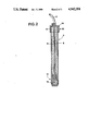
- FIG. 2 is a cutaway view of the device used to carry out the process of the invention.
- FIG. 3 shows a matrix of electrical potentials measured according to the invention.
- FIG. 4 is a schematic illustration of another embodiment of the invention.
- the first step is to make a series of point measurements of the electrical potential of the metal of the strengthening elements 1 embedded in the concrete 2 by moving a reference electrode 3, for example an electrode of the Cu/CuSO 4 type, at regular intervals along the surface 4 of the structure in question.
- a reference electrode 3 for example an electrode of the Cu/CuSO 4 type
- the surface which is most easily accessible, according to the working conditions, will be chosen for this purpose, e.g. the side of a wall or trench, the periphery of a concrete pile or the top or bottom face of the floor of a bridge.
- the measurements will be made in contact with the surface in question, for example every meter, every 50 cm or less, according to the situation encountered; as a general rule, these measurements will be made at regular intervals along two orthogonal axes (for example x and y).
- These measurements are made with a customary voltmeter 5, preferably a voltmeter of high internal resistance, one of the terminals of the said voltmeter 5 being connected to one of the metal elements 1 of the structure, which has been exposed or is directly accessible, and the other terminal of the voltmeter being connected to the reference electrode 3.
- the electrode 3 can be moved by any appropriate means or quite simply by hand; it will be described in detail later.
- the preferred reference electrode is an electrode of the Cu/CuSO 4 type, but it is also possible to use a calomel electrode or an electrode of the Ag/AgCl type.
- the measurements made are then plotted on any suitable medium, for example graph paper, in order to set up a two-dimensional matrix such as that illustrated in FIG. 3.
- This kind of matrix contains series of values which are more or less homogeneous in places, as well as zones in which the measured values vary greatly from point to point.
- steel bars 1 embedded in concrete 2 were found to be free of corrosion if the measured electrical potential was greater than about -200 mV, corrosion of the metal appearing at a potential of between -200 and about -300 mV. Actual corrosion is present at a potential below -300 mV. It is thus possible, by means of the two-dimensional matrix mentioned above, to delimit one or more surface zones 6, 6a, 6b, 6c . . . where the measured electronegative potential is below a limiting value, which in this case is -200 mV.
- one or more point measurements of the relative moisture content of the concrete mass are made below the surface and within the zone defined above, the humidity of the ambient air being taken as the reference value.
- These measurements can be made by any customary means, for example using an electronic probe 20 placed in a sealed hole (e.g., sealed as by a plug 22) made in the concrete mass.
- a relative moisture content of more than 45% in the concrete was found to create a medium favoring the development of steel corrosion.
- These measurements can of course be made at any depth, according to the situation encountered.
- One suitable instrument for measuring moisture content is readily available from Vaisala Oy of Helsinki, Finland, and is sold under the trademark "HUMICAP" humidity instrument.
- Such an instrument includes a probe such as the probe 20 and a meter unit illustrated at reference numeral 21 in FIG. 4.
- the zones of concrete which require treatment are determined as follows:
- zones liable to be damaged by corrosion of the metal strengthening elements measured electronegative potential between about -200 and about -300 mV and relative moisture content greater than about 45% (6, 6a, 6b . . . );
- zones damaged by corrosion of the metal strengthening elements measured electronegative potential below about -300 mV and relative moisture content greater than about 45% (7, 7a, 7b . . . ).
- the zones located in this way can be treated by the customary techniques adapted to the circumstances encountered, especially according to the degree of metal corrosion and concrete damage found. Depending on the particular case, the said treatment will be purely preventive or a zone will be more or less extensively repaired. Types of treatment which may be mentioned are cathodic protection, coating or sealing of a portion of concrete, or even replacement of a portion of damaged concrete by fresh mortar, optionally in combination with an anticorrosion treatment of the metal elements involved.
- a treatment which is both preventive (zones liable to be damaged) and restoring (zones actually damaged), and which is suitable for numerous situations, consists in coating the portion of surface delimited according to the process of the invention, or a larger portion, with a polymerized synthetic material which is preferably impervious to water and air, for example an epoxy resin or a polyurethane resin.
- the reference electrode 3 used to carry out the above process is of the Cu/CuSO 4 type. It comprises a central electrode 8 made of copper metal, immersed in a saturated aqueous solution of CuSO 4 , 9, at its upper end 10 an inflatable chamber 11 immersed in the solution 9, and at its lower end 12 a porous plug 13 in contact with the CuSO 4 solution 9.
- the electrode 3 also comprises a leaktight plug 14 at its upper end and, of course, a cable 15 connecting it to the voltmeter 5.
- the porous plug 13 remains permanently impregnated with CuSO 4 solution and the electrode 3 can be placed in any position without upsetting the precision of the measurement. Any zone of the surface to be inspected can thus be reached easily.
- the effectiveness of the above treatments can be continuously or intermittently monitored by the following procedure: one or more reference electrodes 16 are implanted in the concrete mass 2 and each of the said electrodes 16 is connected to an instrument for measuring the electrical potential, 5, which is itself connected to a metal strengthening element 1 embedded in the concrete 2.
- a voltmeter 5 of high internal resistance is preferably used for the measurements of electrical potential.
- the reference electrode 16 it is possible to use any suitable referene electrode, in particular an electrode of the Cu/CuSO 4 type defined above.
- Another advantageous possibility is to use a lead electrode, which is implanted in the concrete mass at the desired spot. In FIG. 3, the spots marked with an asterisk (*) identify the location of a lead electrode 16. This is generally sealed in the concrete mass with fresh mortar, only its end 17 being in contact with the concrete and the remaining part being protected by an insulating material 18, for example a plastic coating.
- the effectiveness of the treatment applied to the damaged concrete or concrete which is liable to be damaged will therefore be related to the measurement of the corrosion potential: such a process can be used, for example, to follow the regression of corrosion of the metal elements with time. Also, the need to treat concrete can be detected in time by means of measurement made at regular intervals, once certain limiting values have been exceeded.
- the shaded zones 6a, 6b, 6c . . . are those in which the potential measured on the surface is less than -200 mV, the boxed zone 7a being that in which the measured potential is less than -300 mV.
- the measurements of relative moisture content made by probing inside the zone 6a indicate a relative moisture content of 90%.
- the surface of the boxed zone 7a was found to exhibit significant deterioration in the form of cracks due to corrosion of the metal of the strengthening bars.
- the zone 6a (potential less than -200 mV) was coated with a polyurethane resin and, after a few days, the recorded electrical potentials reached about +560 mV. After an area of concrete exceeding the zone 6a had also been coated, the potential measured after a few days reached +650 mV, signifying the effectiveness of the treatment applied.
Abstract
A process is described which makes it possible to locate, on the surface, those zones of reinforced concrete structures which have been damaged or are liable to be damaged by corrosion of the metal strengthening elements embedded in the concrete, with a view to repairing the zones. A process is also described which makes it possible to monitor, continuously or intermittently, the effectiveness of the repairs made to reinforced concrete structures.
Description
This application is a continuation of application Ser. No. 083,718, filed Aug. 10, 1987, now abandoned.
The invention relates to a process which makes it possible to locate, on the surface, those zones of reinforced concrete structures which have been damaged or are liable to be damaged by corrosion of the metal strengthening elements embedded in the concrete, with a view to repairing the said zones.
The invention also relates to a process which makes it possible to monitor, continuously or intermittently, the effectiveness of the repairs made to reinforced concrete structures damaged by corrosion of the metal strengthening elements.
Corrosion of the metal strengthening elements used in the building of reinforced concrete structures causes progressive deterioration of the concrete to varying degrees. In its final stage, this deterioration appears in the form of cracks at the surface of the concrete or even splitting of the concrete mass. The difficulty lies in the fact that, in many cases, it is inadvisable to wait until this stage before acting, but, in the absence of any visible phenomenon, identification of the damaged zones of concrete becomes a matter of chance. At the present time, in fact, there are no non-destructive techniques which make it possible to locate the zones damaged by corrosion of the metal strengthening elements, even less the zones which are liable to be damaged in this way at points where corrosion of the said metal elements is still slight.
It is known that ferrous metals, for example steel, tend to corrode. This phenomenon involves an electrochemical process which depends particularly on the oxygen concentration, moisture content and acidity of the ambient medium, and which can be characterized by its electrical potential. In fact, it is known how to measure the corrosion potential of steel bars embedded in concrete by using a reference electrode such as a calomel electrode or an electrode of the Ag/AgCl or Cu/CuSO4 type.
It has been found, surprisingly, that these measurements of the corrosion potential of steel can advantageously be utilized to locate, at a distance and without first destroying the mass, those zones of reinforced concrete structures which have been damaged or are liable to be damaged by corrosion of the metal elements, and hence the zones which are in need of repair or preventive treatment. This is achieved by carrying out the process of claim 1.
It has also been found that these measurements of corrosion potential can be used to monitor, continuously or intermittently, the effectiveness of the repairs made to reinforced concrete structures, more precisely by carrying out the process of claim 8.
The attached drawings illustrate some particular embodiments of the invention without implying a limitation.
FIG. 1 is a schematic illustration of a first embodiment of the invention.
FIG. 2 is a cutaway view of the device used to carry out the process of the invention.
FIG. 3 shows a matrix of electrical potentials measured according to the invention.
FIG. 4 is a schematic illustration of another embodiment of the invention.
According to the invention, the first step is to make a series of point measurements of the electrical potential of the metal of the strengthening elements 1 embedded in the concrete 2 by moving a reference electrode 3, for example an electrode of the Cu/CuSO4 type, at regular intervals along the surface 4 of the structure in question. The surface which is most easily accessible, according to the working conditions, will be chosen for this purpose, e.g. the side of a wall or trench, the periphery of a concrete pile or the top or bottom face of the floor of a bridge.
The measurements will be made in contact with the surface in question, for example every meter, every 50 cm or less, according to the situation encountered; as a general rule, these measurements will be made at regular intervals along two orthogonal axes (for example x and y). These measurements are made with a customary voltmeter 5, preferably a voltmeter of high internal resistance, one of the terminals of the said voltmeter 5 being connected to one of the metal elements 1 of the structure, which has been exposed or is directly accessible, and the other terminal of the voltmeter being connected to the reference electrode 3. The electrode 3 can be moved by any appropriate means or quite simply by hand; it will be described in detail later. The preferred reference electrode is an electrode of the Cu/CuSO4 type, but it is also possible to use a calomel electrode or an electrode of the Ag/AgCl type.
According to the invention, the measurements made are then plotted on any suitable medium, for example graph paper, in order to set up a two-dimensional matrix such as that illustrated in FIG. 3. This kind of matrix contains series of values which are more or less homogeneous in places, as well as zones in which the measured values vary greatly from point to point.
When using a reference electrode 3 of the Cu/CuSO4 type, steel bars 1 embedded in concrete 2 were found to be free of corrosion if the measured electrical potential was greater than about -200 mV, corrosion of the metal appearing at a potential of between -200 and about -300 mV. Actual corrosion is present at a potential below -300 mV. It is thus possible, by means of the two-dimensional matrix mentioned above, to delimit one or more surface zones 6, 6a, 6b, 6c . . . where the measured electronegative potential is below a limiting value, which in this case is -200 mV.
According to the invention, once the surface zone 6, 6a, 6b . . . has been delimited, one or more point measurements of the relative moisture content of the concrete mass are made below the surface and within the zone defined above, the humidity of the ambient air being taken as the reference value. These measurements can be made by any customary means, for example using an electronic probe 20 placed in a sealed hole (e.g., sealed as by a plug 22) made in the concrete mass. A relative moisture content of more than 45% in the concrete was found to create a medium favoring the development of steel corrosion. These measurements can of course be made at any depth, according to the situation encountered. One suitable instrument for measuring moisture content is readily available from Vaisala Oy of Helsinki, Finland, and is sold under the trademark "HUMICAP" humidity instrument. Such an instrument includes a probe such as the probe 20 and a meter unit illustrated at reference numeral 21 in FIG. 4.
Thus, according to the invention, the zones of concrete which require treatment are determined as follows:
zones liable to be damaged by corrosion of the metal strengthening elements: measured electronegative potential between about -200 and about -300 mV and relative moisture content greater than about 45% (6, 6a, 6b . . . );
zones damaged by corrosion of the metal strengthening elements: measured electronegative potential below about -300 mV and relative moisture content greater than about 45% (7, 7a, 7b . . . ).
The zones located in this way can be treated by the customary techniques adapted to the circumstances encountered, especially according to the degree of metal corrosion and concrete damage found. Depending on the particular case, the said treatment will be purely preventive or a zone will be more or less extensively repaired. Types of treatment which may be mentioned are cathodic protection, coating or sealing of a portion of concrete, or even replacement of a portion of damaged concrete by fresh mortar, optionally in combination with an anticorrosion treatment of the metal elements involved.
A treatment which is both preventive (zones liable to be damaged) and restoring (zones actually damaged), and which is suitable for numerous situations, consists in coating the portion of surface delimited according to the process of the invention, or a larger portion, with a polymerized synthetic material which is preferably impervious to water and air, for example an epoxy resin or a polyurethane resin.
The reference electrode 3 used to carry out the above process is of the Cu/CuSO4 type. It comprises a central electrode 8 made of copper metal, immersed in a saturated aqueous solution of CuSO4, 9, at its upper end 10 an inflatable chamber 11 immersed in the solution 9, and at its lower end 12 a porous plug 13 in contact with the CuSO4 solution 9.
The electrode 3 also comprises a leaktight plug 14 at its upper end and, of course, a cable 15 connecting it to the voltmeter 5. By virture of this novel arrangement, the porous plug 13 remains permanently impregnated with CuSO4 solution and the electrode 3 can be placed in any position without upsetting the precision of the measurement. Any zone of the surface to be inspected can thus be reached easily.
In another embodiment of the invention, the effectiveness of the above treatments can be continuously or intermittently monitored by the following procedure: one or more reference electrodes 16 are implanted in the concrete mass 2 and each of the said electrodes 16 is connected to an instrument for measuring the electrical potential, 5, which is itself connected to a metal strengthening element 1 embedded in the concrete 2. As previously, a voltmeter 5 of high internal resistance is preferably used for the measurements of electrical potential. As the reference electrode 16, it is possible to use any suitable referene electrode, in particular an electrode of the Cu/CuSO4 type defined above. Another advantageous possibility is to use a lead electrode, which is implanted in the concrete mass at the desired spot. In FIG. 3, the spots marked with an asterisk (*) identify the location of a lead electrode 16. This is generally sealed in the concrete mass with fresh mortar, only its end 17 being in contact with the concrete and the remaining part being protected by an insulating material 18, for example a plastic coating.
As regards steel corrosion, the measured electrical potentials were found to correspond as follows:
______________________________________
Cu/CuSO.sub.4          Pb
______________________________________
>-200 mV > +515 mV:    no corrosion
-200 to -300 mV +515 to +415 mV:
                       incipient corrosion
<-300 mV < +415 mV:    substantial corrosion
______________________________________
The effectiveness of the treatment applied to the damaged concrete or concrete which is liable to be damaged will therefore be related to the measurement of the corrosion potential: such a process can be used, for example, to follow the regression of corrosion of the metal elements with time. Also, the need to treat concrete can be detected in time by means of measurement made at regular intervals, once certain limiting values have been exceeded.
An actual example is given below to illustrate one of the numerous applications of the invention.
Electrical potential measurements were made on the bottom face of the floor of a reinforced concrete bridge using a Cu/CuSO4 reference electrode such as that illustrated in FIG. 2. The potential was measured every 50 cm along two orthogonal axes and the measurements were then plotted on a paper medium. The matrix shown in FIG. 3 was thus obtained, giving the distribution of the electronegative potential values recorded (mV).
The shaded zones 6a, 6b, 6c . . . are those in which the potential measured on the surface is less than -200 mV, the boxed zone 7a being that in which the measured potential is less than -300 mV. The measurements of relative moisture content made by probing inside the zone 6a indicate a relative moisture content of 90%. Moreover, the surface of the boxed zone 7a was found to exhibit significant deterioration in the form of cracks due to corrosion of the metal of the strengthening bars.
To treat the concrete, four lead electrodes were then implanted in the concrete, inside the zone 6a, one of the electrodes being inside the boxed zone 7a. The location of these electrodes is given by an asterisk (*): the measured electrical potential is between +380 mV and +423 mV prior to treatment.
The zone 6a (potential less than -200 mV) was coated with a polyurethane resin and, after a few days, the recorded electrical potentials reached about +560 mV. After an area of concrete exceeding the zone 6a had also been coated, the potential measured after a few days reached +650 mV, signifying the effectiveness of the treatment applied.
Experience shows that such potential measurements are reliable, under the usual conditions, down to a depth of at least about 20 cm.
Claims (1)
1. A process for continuously or intermittently monitoring the effectiveness of the repairs made to zones of reinforced concrete structures, which comprises implanting one or more lead reference electrodes (16) in the concrete (2) and connecting each of the said electrodes (16) to an instrument (5) for measuring electrical potential, the said instrument itself being connected to a metal strengthening element (1) embedded in the concrete (2).
Applications Claiming Priority (2)
| Application Number | Priority Date | Filing Date | Title |
|---|---|---|---|
| CH3472/86 | 1986-08-29 | ||
| CH347286 | 1986-08-29 |
Related Parent Applications (1)
| Application Number | Title | Priority Date | Filing Date |
|---|---|---|---|
| US07083718 Continuation-In-Part | 1987-08-10 |
Publications (1)
| Publication Number | Publication Date |
|---|---|
| US4942354A true US4942354A (en) | 1990-07-17 |
Family
ID=4256702
Family Applications (1)
| Application Number | Title | Priority Date | Filing Date |
|---|---|---|---|
| US07/368,994 Expired - Fee Related US4942354A (en) | 1986-08-29 | 1989-06-16 | Process for monitoring the effectiveness of repairs made to zones of reinforced concrete structures |
Country Status (8)
| Country | Link |
|---|---|
| US (1) | US4942354A (en) |
| EP (1) | EP0259253B1 (en) |
| JP (1) | JPH0743336B2 (en) |
| AT (1) | ATE71224T1 (en) |
| DE (1) | DE3775662D1 (en) |
| DK (1) | DK165711C (en) |
| ES (1) | ES2028909T3 (en) |
| FI (1) | FI873507A (en) |
Cited By (17)
| Publication number | Priority date | Publication date | Assignee | Title |
|---|---|---|---|---|
| US5069774A (en) * | 1987-09-19 | 1991-12-03 | University Of Manchester Institute Of Science & Technology | Surface mounting corrosion probe |
| US5087886A (en) * | 1990-09-28 | 1992-02-11 | Mann Harold E | Rain-activated sprinkler shut-off system |
| US5210482A (en) * | 1990-04-26 | 1993-05-11 | L'etat Francais Represente Par Le Laboratoire Central Des Ponts, Et Chaussees | Device for measuring the electrode potential of underwater concrete reinforcement |
| US5239268A (en) * | 1992-06-18 | 1993-08-24 | Asanuma Corp. | Concrete sensor for sensing fresh concrete |
| AU655824B2 (en) * | 1992-06-09 | 1995-01-12 | Asanuma Corporation | Concrete sensor |
| US5403550A (en) * | 1992-02-21 | 1995-04-04 | Wietek; Bernhard | Electrode for determining the state of corrosion of metal renforcement in concrete constructions |
| WO2007096668A1 (en) * | 2006-02-24 | 2007-08-30 | Gareth Glass | Monitoring method |
| GB2449039A (en) * | 2006-02-24 | 2008-11-05 | Gareth Kevin Glass | Monitoring method |
| DE102009029914A1 (en) * | 2009-06-19 | 2010-12-23 | Rheinisch-Westfälische Technische Hochschule Aachen | Method and device for determining the location of corrosion spots in reinforced concrete |
| JP2012237696A (en) * | 2011-05-13 | 2012-12-06 | Seiko Epson Corp | Sensor device |
| CN104155345A (en) * | 2014-09-02 | 2014-11-19 | 国核工程有限公司 | Method for monitoring pouring compactness of self-compacting concrete in large-scale structural module wall |
| US20180340925A1 (en) * | 2016-07-11 | 2018-11-29 | Quipip, Llc | Sensor device, and systems and methods for obtaining measurements of selected characteristics of a concrete mixture |
| US10247691B1 (en) * | 2012-05-30 | 2019-04-02 | University Of South Florida | Systems and methods for contactless assessment of reinforced concrete |
| US10317358B1 (en) | 2016-03-15 | 2019-06-11 | University Of South Florida | Systems and methods for contactless assessment of structures buried in soil |
| CN112780076A (en) * | 2019-11-04 | 2021-05-11 | 河海大学 | High-efficiency electrochemical desalting method and device based on intermittent energization |
| US11300497B2 (en) | 2017-11-06 | 2022-04-12 | Auscultech Inc. | System, electrode and method for evaluating a condition of steel reinforcements in concrete |
| US11360051B2 (en) * | 2018-03-20 | 2022-06-14 | Industry-University Cooperation Foundation Hanyang University Erica Campus | Construction structure corrosion measurement sensor assembly and method for measuring corrosion by using same |
Families Citing this family (7)
| Publication number | Priority date | Publication date | Assignee | Title |
|---|---|---|---|---|
| DE3834628A1 (en) * | 1988-10-11 | 1990-04-12 | Peter Dr Ing Schiessl | CORROSION MEASURING CELL |
| IT1273729B (en) * | 1994-07-22 | 1997-07-09 | Cescor Srl | DEVICES FOR MEASURING POTENTIAL IN THE LAND AND CONCRETE IN THE PRESENCE OF VARIABLE ELECTRIC FIELDS |
| GB0028799D0 (en) * | 2000-11-24 | 2001-01-10 | United Utilities Plc | Identifying buried pipe materials |
| JP2012017456A (en) | 2010-06-11 | 2012-01-26 | Fujifilm Corp | Polyester film and method for producing the same, back sheet for solar cell, and solar cell module |
| JP5733110B2 (en) * | 2011-08-30 | 2015-06-10 | 東京電力株式会社 | Damaged part protection method and inspection method |
| JP6850953B2 (en) * | 2016-02-08 | 2021-03-31 | 東電設計株式会社 | Reinforcing bar corrosion judgment method and rebar corrosion judgment program |
| DE102016222538B3 (en) * | 2016-11-16 | 2018-02-22 | Fachhochschule Erfurt | Method and arrangement for assessing the corrosion and passivation of the reinforcement taking into account the moisture in reinforced concrete |
Citations (11)
| Publication number | Priority date | Publication date | Assignee | Title |
|---|---|---|---|---|
| FR1550326A (en) * | 1967-11-07 | 1968-12-20 | ||
| US3999121A (en) * | 1975-08-11 | 1976-12-21 | Standard Oil Company (Indiana) | Well casing corrosion meter |
| US4003815A (en) * | 1973-03-12 | 1977-01-18 | Sanyo Electric Co., Ltd. | Apparatus for measuring stray current electrolytic corrosion |
| DE2755644A1 (en) * | 1976-12-17 | 1978-06-22 | Jahn H H O | WALL EXAMINATION |
| US4209376A (en) * | 1974-05-08 | 1980-06-24 | Sanyo Electric Co., Ltd. | Apparatus for integrating electrolytic corrosion associated voltage |
| GB1584506A (en) * | 1977-05-30 | 1981-02-11 | Japan Atomic Energy Res Inst | Package for sea disposal or storage on land of radioactive or industrial waste |
| US4347429A (en) * | 1979-06-28 | 1982-08-31 | General Electric Company | High capacity corrosion and erosion resistant electrodes for AC electrode boilers |
| US4481474A (en) * | 1981-06-26 | 1984-11-06 | N.V. Nederlandse Gasunie | Device for measurement of the potential with respect to the soil of a cathodically protected metallic structure |
| GB2157441A (en) * | 1984-03-26 | 1985-10-23 | Taylor Woodrow Const Ltd | A device for determining corrosion of reinforcing members in concrete |
| US4623434A (en) * | 1983-01-31 | 1986-11-18 | Nicholson John P | Method of determining cathodic corrosion and displaying |
| EP0216628A2 (en) * | 1985-09-24 | 1987-04-01 | Colebrand Limited | Corrosion detection |
Family Cites Families (2)
| Publication number | Priority date | Publication date | Assignee | Title |
|---|---|---|---|---|
| JPS59217147A (en) * | 1983-05-25 | 1984-12-07 | Nippon Kenchiku Sogo Shikenjo | Method and apparatus for inspecting corrosion of steel material in concrete |
| JPS61124863A (en) * | 1984-11-21 | 1986-06-12 | Kajima Corp | Method for measuring potential of reinforcing bar in concrete |
-
1987
- 1987-08-12 FI FI873507A patent/FI873507A/en not_active Application Discontinuation
- 1987-08-17 EP EP87810463A patent/EP0259253B1/en not_active Expired - Lifetime
- 1987-08-17 DK DK428387A patent/DK165711C/en not_active IP Right Cessation
- 1987-08-17 DE DE8787810463T patent/DE3775662D1/en not_active Expired - Fee Related
- 1987-08-17 ES ES198787810463T patent/ES2028909T3/en not_active Expired - Lifetime
- 1987-08-17 AT AT87810463T patent/ATE71224T1/en not_active IP Right Cessation
- 1987-08-27 JP JP62216265A patent/JPH0743336B2/en not_active Expired - Lifetime
-
1989
- 1989-06-16 US US07/368,994 patent/US4942354A/en not_active Expired - Fee Related
Patent Citations (11)
| Publication number | Priority date | Publication date | Assignee | Title |
|---|---|---|---|---|
| FR1550326A (en) * | 1967-11-07 | 1968-12-20 | ||
| US4003815A (en) * | 1973-03-12 | 1977-01-18 | Sanyo Electric Co., Ltd. | Apparatus for measuring stray current electrolytic corrosion |
| US4209376A (en) * | 1974-05-08 | 1980-06-24 | Sanyo Electric Co., Ltd. | Apparatus for integrating electrolytic corrosion associated voltage |
| US3999121A (en) * | 1975-08-11 | 1976-12-21 | Standard Oil Company (Indiana) | Well casing corrosion meter |
| DE2755644A1 (en) * | 1976-12-17 | 1978-06-22 | Jahn H H O | WALL EXAMINATION |
| GB1584506A (en) * | 1977-05-30 | 1981-02-11 | Japan Atomic Energy Res Inst | Package for sea disposal or storage on land of radioactive or industrial waste |
| US4347429A (en) * | 1979-06-28 | 1982-08-31 | General Electric Company | High capacity corrosion and erosion resistant electrodes for AC electrode boilers |
| US4481474A (en) * | 1981-06-26 | 1984-11-06 | N.V. Nederlandse Gasunie | Device for measurement of the potential with respect to the soil of a cathodically protected metallic structure |
| US4623434A (en) * | 1983-01-31 | 1986-11-18 | Nicholson John P | Method of determining cathodic corrosion and displaying |
| GB2157441A (en) * | 1984-03-26 | 1985-10-23 | Taylor Woodrow Const Ltd | A device for determining corrosion of reinforcing members in concrete |
| EP0216628A2 (en) * | 1985-09-24 | 1987-04-01 | Colebrand Limited | Corrosion detection |
Non-Patent Citations (6)
| Title |
|---|
| Andrade et al., "Quantitative Measurements of Corrosion . . . ," Werkstoffe und Korrosion, 29, 515-519 (1978). |
| Andrade et al., Quantitative Measurements of Corrosion . . . , Werkstoffe und Korrosion, 29, 515 519 (1978). * |
| McKenzie, "Techniques for Monitoring Corrosion of Steel in Concrete," Corrosion Prevention & Control, Feb. 1987, pp. 11-17. |
| McKenzie, Techniques for Monitoring Corrosion of Steel in Concrete, Corrosion Prevention & Control, Feb. 1987, pp. 11 17. * |
| Patent Abstracts of Japan, 19 Apr. 1985, vol. 9, No. 90, P 350, JPA 59 217 147, 59 217147. * |
| Patent Abstracts of Japan, 19 Apr. 1985, vol. 9, No. 90, P-350, JPA 59 217 147, 59-217147. |
Cited By (23)
| Publication number | Priority date | Publication date | Assignee | Title |
|---|---|---|---|---|
| US5069774A (en) * | 1987-09-19 | 1991-12-03 | University Of Manchester Institute Of Science & Technology | Surface mounting corrosion probe |
| US5210482A (en) * | 1990-04-26 | 1993-05-11 | L'etat Francais Represente Par Le Laboratoire Central Des Ponts, Et Chaussees | Device for measuring the electrode potential of underwater concrete reinforcement |
| US5087886A (en) * | 1990-09-28 | 1992-02-11 | Mann Harold E | Rain-activated sprinkler shut-off system |
| US5403550A (en) * | 1992-02-21 | 1995-04-04 | Wietek; Bernhard | Electrode for determining the state of corrosion of metal renforcement in concrete constructions |
| AU655824B2 (en) * | 1992-06-09 | 1995-01-12 | Asanuma Corporation | Concrete sensor |
| US5239268A (en) * | 1992-06-18 | 1993-08-24 | Asanuma Corp. | Concrete sensor for sensing fresh concrete |
| WO2007096668A1 (en) * | 2006-02-24 | 2007-08-30 | Gareth Glass | Monitoring method |
| GB2449039A (en) * | 2006-02-24 | 2008-11-05 | Gareth Kevin Glass | Monitoring method |
| GB2449039B (en) * | 2006-02-24 | 2010-02-17 | Gareth Kevin Glass | Monitoring method |
| US8778167B2 (en) | 2009-06-19 | 2014-07-15 | Rheinisch-Westfaelische-Technische Hochschule Aachen | Method and device for determining the location of corrosion sites in reinforced concrete |
| DE102009029914A1 (en) * | 2009-06-19 | 2010-12-23 | Rheinisch-Westfälische Technische Hochschule Aachen | Method and device for determining the location of corrosion spots in reinforced concrete |
| JP2012237696A (en) * | 2011-05-13 | 2012-12-06 | Seiko Epson Corp | Sensor device |
| US20160103086A1 (en) * | 2011-05-13 | 2016-04-14 | Seiko Epson Corporation | Sensor device |
| US10393688B2 (en) * | 2011-05-13 | 2019-08-27 | Seiko Epson Corporation | Sensor device |
| US10247691B1 (en) * | 2012-05-30 | 2019-04-02 | University Of South Florida | Systems and methods for contactless assessment of reinforced concrete |
| CN104155345A (en) * | 2014-09-02 | 2014-11-19 | 国核工程有限公司 | Method for monitoring pouring compactness of self-compacting concrete in large-scale structural module wall |
| US10317358B1 (en) | 2016-03-15 | 2019-06-11 | University Of South Florida | Systems and methods for contactless assessment of structures buried in soil |
| US11099148B1 (en) | 2016-03-15 | 2021-08-24 | University Of South Florida | Systems and methods for contactless assessment of structures buried in soil |
| US20180340925A1 (en) * | 2016-07-11 | 2018-11-29 | Quipip, Llc | Sensor device, and systems and methods for obtaining measurements of selected characteristics of a concrete mixture |
| US11815504B2 (en) * | 2016-07-11 | 2023-11-14 | Quipip, Llc | Sensor device, and systems and methods for obtaining measurements of selected characteristics of a concrete mixture |
| US11300497B2 (en) | 2017-11-06 | 2022-04-12 | Auscultech Inc. | System, electrode and method for evaluating a condition of steel reinforcements in concrete |
| US11360051B2 (en) * | 2018-03-20 | 2022-06-14 | Industry-University Cooperation Foundation Hanyang University Erica Campus | Construction structure corrosion measurement sensor assembly and method for measuring corrosion by using same |
| CN112780076A (en) * | 2019-11-04 | 2021-05-11 | 河海大学 | High-efficiency electrochemical desalting method and device based on intermittent energization |
Also Published As
| Publication number | Publication date |
|---|---|
| JPH0743336B2 (en) | 1995-05-15 |
| DK165711C (en) | 1993-06-07 |
| ES2028909T3 (en) | 1992-07-16 |
| DK165711B (en) | 1993-01-04 |
| DK428387A (en) | 1988-03-01 |
| EP0259253A3 (en) | 1989-07-19 |
| EP0259253B1 (en) | 1992-01-02 |
| FI873507A0 (en) | 1987-08-12 |
| DK428387D0 (en) | 1987-08-17 |
| DE3775662D1 (en) | 1992-02-13 |
| EP0259253A2 (en) | 1988-03-09 |
| JPS6367558A (en) | 1988-03-26 |
| FI873507A (en) | 1988-03-01 |
| ATE71224T1 (en) | 1992-01-15 |
Similar Documents
| Publication | Publication Date | Title |
|---|---|---|
| US4942354A (en) | Process for monitoring the effectiveness of repairs made to zones of reinforced concrete structures | |
| Law et al. | Measurement of loss of steel from reinforcing bars in concrete using linear polarisation resistance measurements | |
| Millard et al. | Environmental influences on linear polarisation corrosion rate measurement in reinforced concrete | |
| Elsener et al. | Half-cell potential measurements—Potential mapping on reinforced concrete structures | |
| Duffó et al. | Development of an embeddable sensor to monitor the corrosion process of new and existing reinforced concrete structures | |
| Elsener et al. | Non destructive determination of the free chloride content in cement based materials | |
| Legat et al. | Corrosion processes of steel in concrete characterized by means of electrochemical noise | |
| US10488389B2 (en) | System for assessing chloride concentration and corresponding method and sensor | |
| US4351703A (en) | Cathodic protection monitoring | |
| US3649492A (en) | Method for determining the completeness of cathodic protection of corrodible metal structure | |
| Sagüés | Corrosion measurement techniques for steel in concrete | |
| Sagues et al. | Corrosion performance of epoxy-coated reinforcing steel in marine substructure service | |
| Berke et al. | Electrochemical methods of determining the corrosivity of steel in concrete | |
| EP0245116A2 (en) | Apparatus and method for measuring resistivity | |
| US4915910A (en) | Corrosion monitoring apparatus | |
| Enos et al. | Impressed current cathodic protection of steel reinforced concrete pilings: Protection criteria and the threshold for Hydrogen embrittlement | |
| JPS59217147A (en) | Method and apparatus for inspecting corrosion of steel material in concrete | |
| Francois et al. | Electrode potential measurements of concrete reinforcement for corrosion evaluation | |
| Pangrazzi et al. | Cathodic polarization and protection of simulated prestressed concrete pilings in seawater | |
| Erdogdu et al. | Field and laboratory testing of epoxy-coated reinforcing bars in concrete | |
| US3549993A (en) | Corrosion rate measuring method by maintaining electrolytic contact and excluding any substantial oxygen contact with a test specimen | |
| Sergi et al. | Control of reinforcement corrosion by surface treatment of concrete | |
| Bjegovic et al. | Test protocols for migrating corrosion inhibitors (MCI®) in reinforced concrete | |
| Qian et al. | Evaluation of Reinforcement Corrosion in Repaired Concrete Bridge SlabsA Case Study | |
| White et al. | The corrosion coulometer—a new corrosion monitor for steel structures |
Legal Events
| Date | Code | Title | Description |
|---|---|---|---|
| REMI | Maintenance fee reminder mailed | ||
| LAPS | Lapse for failure to pay maintenance fees | ||
| FP | Lapsed due to failure to pay maintenance fee |
Effective date: 19940720 |
|
| STCH | Information on status: patent discontinuation |
Free format text: PATENT EXPIRED DUE TO NONPAYMENT OF MAINTENANCE FEES UNDER 37 CFR 1.362 |