US4948356A - Tooling for sealing blow molded bottle - Google Patents
Tooling for sealing blow molded bottle Download PDFInfo
- Publication number
- US4948356A US4948356A US07/382,775 US38277589A US4948356A US 4948356 A US4948356 A US 4948356A US 38277589 A US38277589 A US 38277589A US 4948356 A US4948356 A US 4948356A
- Authority
- US
- United States
- Prior art keywords
- mold
- sealing
- drive
- parison
- follower
- Prior art date
- Legal status (The legal status is an assumption and is not a legal conclusion. Google has not performed a legal analysis and makes no representation as to the accuracy of the status listed.)
- Expired - Lifetime
Links
Images


Classifications
-
- B—PERFORMING OPERATIONS; TRANSPORTING
- B29—WORKING OF PLASTICS; WORKING OF SUBSTANCES IN A PLASTIC STATE IN GENERAL
- B29C—SHAPING OR JOINING OF PLASTICS; SHAPING OF MATERIAL IN A PLASTIC STATE, NOT OTHERWISE PROVIDED FOR; AFTER-TREATMENT OF THE SHAPED PRODUCTS, e.g. REPAIRING
- B29C49/00—Blow-moulding, i.e. blowing a preform or parison to a desired shape within a mould; Apparatus therefor
- B29C49/42—Component parts, details or accessories; Auxiliary operations
- B29C49/48—Moulds
- B29C49/4802—Moulds with means for locally compressing part(s) of the parison in the main blowing cavity
- B29C49/4817—Moulds with means for locally compressing part(s) of the parison in the main blowing cavity with means for closing off parison ends
Definitions
- This invention relates a seal and tooling and methods for blow molding thermoplastic resin bottles in a mold and sealing the interior of the bottle prior to ejection from the mold.
- bottles It is conventional to blow mold thermoplastic resin bottles and seal the bottles closed prior to ejection from the mold.
- the bottles may be sealed empty or after they have been filled, commonly with a liquid. Sealed bottles may be blown using sterile blow air so that the sealed interior is kept aseptic and there is no need to sterilize the interior of the bottles prior to filling. Bottles of this type are used to package food products, medical supplies, blood and other contents requiring sterile packaging.
- the sealing tooling of the present invention is used in a blow molding machine and provides reliable triple redundant seals closing the interior of a blow molded thermoplastic resin bottle, preferably blown using sterile air with a sterile interior.
- the triple seal maintains the sterility of the interior of the bottle, despite the risk that an individual seal may fail.
- the tooling is very compact and easily mounted in conventional blow mold equipment without projecting beyond the normal confines of the mold and support plate.
- a relatively small air cylinder having a drive stroke extending perpendicular to the direction of sealing actuates a force multiplying right angle drive to move a sealing blade across a seal neck to weld the opposite sides of the hot, plastic in the neck against each other and form a seal.
- Each of the two complimentary mold halves carries sealing tooling of this type with the two sealing blades located at different elevations along the seal neck. Extension of both of the blades in opposite directions across the recess forms a pair of spaced seals on opposite sides of the recess and also forms a seal between the two diagonal layers of plastic extending between the blade seals.
- the force multiplying capability of the right angle drives permits relatively small diameter drive cylinders easily mounted on the blow molding machine to drive the blades with the high sealing force needed to make reliable seals.
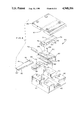
- FIG. 1 is a plan view of the top of a mold half used for blow molding a molded bottle according to the invention
- FIG. 2 is a sectional view taken along line 2--2 of FIG. 1 showing the mold halves closed;
- FIG. 3 is a sectional view taken along line 3--3 of FIG. 2;
- FIG. 4 is an exploded view of the right angle drive connection for the sealing tooling
- FIGS. 5 and 6 illustrate a bottle blown between the mold halves before sealing and after sealing respectively
- FIG. 7 is an enlarged view illustrating the retracted position of one sealing blade.
- the drawings illustrate a pair of complimentary blow mold halves 10 and 12 of a blow molding machine (not illustrated).
- the mold halves when closed define bottle recess 14, blow dome recess 16 and reduced area rectangular seal neck 18 connecting recesses 14 and 16.
- a blow needle (not illustrated) is mounted in mold half 10 and extends into the blow dome recess through opening 20.
- the mold halves 10 and 12 are mounted on supporting plates or platens 22 and 24. In turn the plates 22 and 24 are connected to a drive for opening and closing the mold halves as required during the blow molding operation.
- the blow molding machine includes an extruder for flowing a molten thermoplastic resin parison between the mold halves when open.
- the plastic in the parison may be a high density polyethylene resin although other resins, or even co-extruded resins, may be used as desired.
- Right angle parison sealing tooling 26 is mounted in mold half 10 and supporting plate 22, and includes a flat sealing blade 28 extendable across the seal neck 18 for sealing the portion of the parison confined within the neck.
- a second right angle parison sealing tooling 30, identical to tooling 26, is mounted in mold 12 and plate 24 and includes a sealing blade 32 like blade 28 also extendable into and across the seal neck for sealing the parison confined within the neck. Blades 28 and 32 are spaced apart along the seal neck to assure that each blade forms an independent parison seal.
- Each sealing tooling includes an air cylinder 34 and a flat right angle force-multiplying drive 36 connecting the piston rod of cylinder 34 to the respective blade 28, 32.
- Cylinders 34 are confined within recesses 38 formed in the mold half and adjacent plate and each connection 36 is located within a flat recess 40 likewise formed in the mold half and adjacent plate.
- the recesses 38 and 40 are as indicated generally in FIG. 1 and as illustrated in FIG. 3, extend to the opposite sides of the mold halves.
- the two sets of sealing tooling 26 and 30 are identical. Sealing blades 28 and 32 are located to one side of the center of the drive connections 36 so that they are located at different levels in the seal neck while the recesses 38 and 40 in the mold halves are at the same level.
- FIG. 4 is an exploded view illustrating a right angle drive connection 36, piston rod 42 of a cylinder 34 and one of the sealing blades 26, 32, identified by reference number 44.
- the drive connection 36 includes a rectangular guide block 46 including a central wedge block slot 48 and a shallow sealing slide slot 50 extending perpendicular to and to either side of slot 48. Rectangular wedge block 52 is slidingly fitted in slot 48.
- the end of the piston rod 42 is fitted within bore 54 extending into one end of block 52 and is secured to the block by pin 56.
- a flat angled drive cam surface 58 is formed on the side of block 52 adjacent blade 44, to either side of guide walls 60. Walls 60 align the block in slot 48 during extension and retraction strokes.
- a flat angled return surface 62 extends across the top of block 52 parallel to drive cam surface 58.
- the end 64 of sealing blade 44 remote from seal neck 18 is fitted within notch 66 in cross slide 68.
- the slide carries an angled cam follower surface 70 having the same slope as surfaces 58 and 62.
- Return plate 72 includes a thick end 74, thin end 76 and a angled slot 78 between the ends defined by wide angled slide surface 80 adjacent end 74 and angled narrow return follower surface 82 adjacent thin end 76. All of surfaces 58, 62, 70 and 82 extend at the same angle and are parallel when the drive connection is assembled. Thick end 74 of the return plate is positioned above end 64 of blade 44 and slide 68. The blade, plate and slide are secured together unitarily by pin 84 fitted in suitable bores in the respective members as illustrated.
- the blade 44, slide 68 and plate 72 When assembled, the blade 44, slide 68 and plate 72 form a blade assembly 86 with the free end of the slide extending into the wedge block 52 between guide walls 60 and with the follower surface 70 flush on the parallel drive cam surface 58.
- the return plate extends along the adjacent side of the wedge block with the narrow return follower surface 82 located adjacent and parallel to the return cam surface 62.
- Wedge block 52 is fitted within slot 48 with the blade assembly 86 fitted in slide slot 50 extending transversely to slot 48.
- Cover plate 88 is mounted on top of the guide block 46 by suitable guide pins and cap screws and includes slot 90 slidably receiving the top of the return plate 72.
- FIGS. 2 and 3 illustrate the positions of the drive connections 36 in the mold halves and plates.
- Recesses 38 and 40 open to the back surface of the respective plates 22 and 24 thereby permitting mounting of the cylinders and drive connections to the mold halves by suitable cap screws 92 illustrated in FIG. 3.
- Sealing blades 28 and 32 are fitted in slide guides 94 formed in the mold halves.
- the ends 96 of flat blades 28 and 32 are reduced in width and extend through complimentary slide guides 98 of heat retention inserts 100 carried by the mold halves 10 and 12.
- Inserts 100 are fitted in complimentary recesses 102 formed in mold halves 10 and 12 and define the rectangular seal neck 18.
- the inserts 100 locate the inserts in recesses 102 and cooperate to define air gaps 108 between the inserts and the mold halves.
- the air gaps extend substantially around the majority of the surface area of the inserts and may have a depth of approximately 0.030 inch. These gaps limit the flow of heat from the inserts to the cooled mold halves.
- the mold halves 10 and 12 are conventionally manufactured from conductive aluminum and include internal cooling channels (not illustrated) for maintaining the molds at the relatively low temperature required to set the plastic following blow molding.
- the inserts 100 are made of a relatively nonconductive material, such as titanium, to reduce cooling of the plastic confined in the seal neck 18.
- sealing blades 28 and 32 are surrounded by circumferential air gaps 108 from the end of the short length slide bore 98 a distance away from the seal neck 18 until the width of the blades increase. This gap further reduces heat transfer from the ends of the blades to the cool mold halves. Flash recesses 110 are provided in the faces of inserts 100 to either side of the recesses 18. See FIG. 3.
- the sealing tips 110' of blades 28 and 32 are smoothly rounded along the width of the seal neck as illustrated in FIG. 7. When the blades are retracted, the tips are withdrawn flush to the side of the seal neck 18.
- Each sealing blade is extended into and retracted from the seal neck recess by extension and retraction of its respective cylinder 34.
- the cylinder 34 With the cylinder 34 in the retracted position, as shown in FIGS. 2 and 3, the blades are retracted and are flush to seal neck recesses 18.
- Extension of the cylinders moves the wedge blocks 52 from the retracted positions shown in FIG. 3 to the ends of the slots 48.
- Cam surfaces 58 on blocks 52 are moved along the complimentary follower surfaces 70 of the blade assemblies 86 thereby driving the assemblies in a transverse direction away from surface 58 and moving the sealing blades 28 and 32 from their retracted positions of FIG. 3 to the extended positions shown in FIG.
- sealing tips 110 are moved across the seal neck 18, and, with full extension of cylinders 34, are located a short distance from the opposite side of the seal neck.
- the sealing blades are retracted from the extended positions by retracting cylinders 34 so that the return cam surfaces 62 of blocks 52 are brought into engagement with the return follower surfaces 82 of blade assemblies 86 thereby retracting the assemblies and moving the blades back to the retracted position of FIG. 2.
- drive connection 36 use drive cam and follower surfaces having a shallow angle to the drive stroke of cylinder 34, thereby multiplying the extension force of the cylinder 34 by a factor of about 2.4 to increase the sealing force at the blades.
- the drive correspondingly reduces the stroke of the sealing blades.
- Cylinders 34 may have a one inch stroke and use line air pressure sufficient to exert a maximum force of about 245 pounds.
- the drive connections reduce the stroke of the sealing blades to approximately 0.414 inch while increasing the sealing force to approximately 587 pounds.
- mold halves 10 and 12 are open and cylinders 34 are retracted to retract the sealing blades 28 and 32.
- a plastic resin parison is positioned between the mold halves in alignment with recesses 14, 16 and 18 and the mold halves are closed on the parison.
- a blow needle is extended through opening 20 into the blow dome recess to puncture the parison following which blow air, which may be sterile, is flowed through the needle and into the confined parison to inflate the parison against the walls of the mold cavity.
- Recesses 16 and 14 are cooled by manifolds in the mold halves so that the skin of the inflated hot plastic in the recess is quickly cooled below the set temperature and hardens to form rigid blow dome 112 and bottle 114 shown in FIG. 5.
- the rectangular tube of plastic 116 confined in the rectangular seal neck 18 is held against the relatively hot, heat retention inserts 100 and is not cooled below the set temperature.
- each blade forces the adjacent layer of hot, molten and formable plastic across the seal neck and drives the plastic into welded engagement with the layer of hot, molten and formable plastic on the opposite side of the seal neck to weld the two layers together and form a seal 118 extending across the width of the seal neck and closing off the interior 120 of bottle 114.
- Each blade forms an axially spaced and separate seal 118 as shown in FIG. 6.
- extension of the blades across the seal neck moves the two layers of the plastic on each side of the seal neck between the blades diagonally across the seal neck and into contact with each other to form a third, independent seal 122 closing the bottle interior 120.
- This seal extends generally diagonally across the width of the seal neck as illustrated in FIG. 6.
- the thickness of the parison may be increased at the seal neck to provide additional hot plastic for making the seals.
- the blades are maintained extended for a few seconds to assure formation of the seals.
- cylinders 34 are retracted to retract the sealing blades 28 and 32, the mold halves open and the blown and sealed bottle is ejected.
- Extension of the sealing blades forms three independent seals, each of which closes off the interior of the bottle 114.
- triple redundant seals is important in volume manufacturing processes because there is always a finite possibility, however small, that an individual seal may fail.
- the provision of redundant seals reduces the likelihood that for a given bottle all the seals will fail and the bottle will be rejected. This likelihood is a very small number, the product of the probabilities of failure of each individual seal. For practical purposes, provision of a double or triple redundant seal assures that the bottles are effectively sealed.
Abstract
Description
Claims (24)
Priority Applications (2)
| Application Number | Priority Date | Filing Date | Title |
|---|---|---|---|
| US07/382,775 US4948356A (en) | 1989-07-19 | 1989-07-19 | Tooling for sealing blow molded bottle |
| US07/423,056 US5022544A (en) | 1989-07-19 | 1989-10-18 | Sealed bottle |
Applications Claiming Priority (1)
| Application Number | Priority Date | Filing Date | Title |
|---|---|---|---|
| US07/382,775 US4948356A (en) | 1989-07-19 | 1989-07-19 | Tooling for sealing blow molded bottle |
Related Child Applications (1)
| Application Number | Title | Priority Date | Filing Date |
|---|---|---|---|
| US07/423,056 Division US5022544A (en) | 1989-07-19 | 1989-10-18 | Sealed bottle |
Publications (1)
| Publication Number | Publication Date |
|---|---|
| US4948356A true US4948356A (en) | 1990-08-14 |
Family
ID=23510371
Family Applications (1)
| Application Number | Title | Priority Date | Filing Date |
|---|---|---|---|
| US07/382,775 Expired - Lifetime US4948356A (en) | 1989-07-19 | 1989-07-19 | Tooling for sealing blow molded bottle |
Country Status (1)
| Country | Link |
|---|---|
| US (1) | US4948356A (en) |
Cited By (13)
| Publication number | Priority date | Publication date | Assignee | Title |
|---|---|---|---|---|
| US5068075A (en) * | 1989-07-19 | 1991-11-26 | Graham Engineering Corporation | Method of blow molding aseptic bottles |
| US6602458B1 (en) | 2000-06-28 | 2003-08-05 | Rubbermaid Incorporated | Reduced flash molding |
| US6635216B2 (en) | 2001-05-18 | 2003-10-21 | Graham Engineering Corporation | Blow molding machine and method |
| US20050046088A1 (en) * | 2003-09-03 | 2005-03-03 | Brandner Brian W. | Method and apparatus for making a blow molded fuel tank |
| US7150624B1 (en) | 2000-05-24 | 2006-12-19 | Uniloy Milacron Inc. | Sealing blade |
| WO2007101466A1 (en) * | 2006-03-01 | 2007-09-13 | Bernd Hansen | Container and apparatus for producing the same |
| US20090071104A1 (en) * | 2005-03-16 | 2009-03-19 | Krones Ag | Method and device for the sterile filling with fluids |
| US20100094245A1 (en) * | 2008-10-10 | 2010-04-15 | Daniel Py | Co-extrusion blow molding apparatus and method, and sealed empty devices |
| US7866514B1 (en) | 2006-03-01 | 2011-01-11 | Bernd Hansen | Container and device for production of such container |
| US20140366485A1 (en) * | 2013-06-17 | 2014-12-18 | The Clorox Company | Skin antiseptic applicator and methods of making and using the same |
| US20160136867A1 (en) * | 2013-07-08 | 2016-05-19 | Isp Technology Ag | Plastics connecting seam, plastics bottle with a connecting seam and method for the production thereof |
| USD807934S1 (en) * | 2015-10-29 | 2018-01-16 | Bando Chemical Industries, Ltd. | Sealing blade for working machine |
| USD873315S1 (en) * | 2015-11-25 | 2020-01-21 | Bando Chemical Industries, Ltd. | Sealing blade for working machine |
Citations (28)
| Publication number | Priority date | Publication date | Assignee | Title |
|---|---|---|---|---|
| US2541249A (en) * | 1947-08-12 | 1951-02-13 | Plax Corp | Multiple cavity mold |
| US3292209A (en) * | 1963-12-10 | 1966-12-20 | American Can Co | Labeling apparatus |
| US3356244A (en) * | 1966-03-28 | 1967-12-05 | Leco Industries Ltd | Container for convenient opening |
| US3363282A (en) * | 1963-07-06 | 1968-01-16 | Hagen Reinold | Apparatus for the production of hollow plastic articles |
| US3369690A (en) * | 1964-12-28 | 1968-02-20 | American Can Co | Plastic container with integral carrying handle |
| US3423495A (en) * | 1965-04-30 | 1969-01-21 | Carroll Street Corp | Blow molding method and apparatus |
| FR1566102A (en) * | 1967-06-05 | 1969-05-02 | ||
| US3464085A (en) * | 1966-09-26 | 1969-09-02 | Dow Chemical Co | Packaging apparatus |
| US3519705A (en) * | 1965-12-07 | 1970-07-07 | Pannenbecker H | Method of molding and filling plastic containers |
| FR2042538A1 (en) * | 1969-05-10 | 1971-02-12 | Hansen Gerhard | Plastic container with integral cap |
| US3691267A (en) * | 1968-09-25 | 1972-09-12 | Hiraki Takehara | Sanitary process of packing a subject into a vessel |
| US3736091A (en) * | 1971-03-03 | 1973-05-29 | Monsanto Co | Apparatus for finishing hollow blow molded articles |
| US3765144A (en) * | 1971-04-05 | 1973-10-16 | Netstal Ag | Method for closing plastic containers |
| US3814783A (en) * | 1971-02-12 | 1974-06-04 | Remy & Cie E P | Method for manufacturing sterile containers |
| US3851029A (en) * | 1973-03-07 | 1974-11-26 | Respiratory Care | Method for molding and sealing thermoplastic containers |
| US3861846A (en) * | 1972-09-21 | 1975-01-21 | Remy & Cie E P | Moulds for manufacturing through extrusion-blowing of sealed containers made from plastics material |
| US4026982A (en) * | 1974-03-22 | 1977-05-31 | E.P. Remy Et Cie | Method of automatic manufacture of closed, internally sterile hollow bodies |
| US4052986A (en) * | 1974-10-09 | 1977-10-11 | Reckitt & Colman Products Limited | Device for introducing medicaments or the like into body cavities |
| US4178976A (en) * | 1978-02-10 | 1979-12-18 | Automatic Liquid Packaging, Inc. | Unitary, hermetically-sealed but pierceable dispensing container |
| US4266927A (en) * | 1979-02-21 | 1981-05-12 | Baxter Travenol Laboratories, Inc. | Apparatus for molding a plastic article |
| US4401423A (en) * | 1981-03-20 | 1983-08-30 | Societe De Machines Pour La Transformation Des Plastiques | Apparatus for blow molding hollow plastic bodies |
| US4425090A (en) * | 1980-09-09 | 1984-01-10 | Gerhard Hansen | Apparatus for producing a heat-sealable container |
| US4510115A (en) * | 1982-11-03 | 1985-04-09 | Baxter Travenol Laboratories, Inc. | Method for forming layered thermoplastic articles |
| US4540542A (en) * | 1983-06-29 | 1985-09-10 | Automatic Liquid Packaging, Inc. | Method for making a container with a unitary but removable closure |
| US4574965A (en) * | 1984-05-30 | 1986-03-11 | Health Care Concepts, Inc. | Container with integrally formed piercing site |
| US4671763A (en) * | 1983-06-29 | 1987-06-09 | Automatic Liquid Packaging, Inc. | Container with a unitary but removable closure and method and apparatus therefor |
| US4707966A (en) * | 1981-08-26 | 1987-11-24 | Automatic Liquid Packaging, Inc. | Container with an encapsulated top insert and method and apparatus for making same |
| US4719072A (en) * | 1984-05-08 | 1988-01-12 | Ishikawajima-Harima Jukogyo Kabushiki Kaisha | Method for disposing inner insert in blow molding |
-
1989
- 1989-07-19 US US07/382,775 patent/US4948356A/en not_active Expired - Lifetime
Patent Citations (29)
| Publication number | Priority date | Publication date | Assignee | Title |
|---|---|---|---|---|
| US2541249A (en) * | 1947-08-12 | 1951-02-13 | Plax Corp | Multiple cavity mold |
| US3363282A (en) * | 1963-07-06 | 1968-01-16 | Hagen Reinold | Apparatus for the production of hollow plastic articles |
| US3292209A (en) * | 1963-12-10 | 1966-12-20 | American Can Co | Labeling apparatus |
| US3369690A (en) * | 1964-12-28 | 1968-02-20 | American Can Co | Plastic container with integral carrying handle |
| US3423495A (en) * | 1965-04-30 | 1969-01-21 | Carroll Street Corp | Blow molding method and apparatus |
| US3519705A (en) * | 1965-12-07 | 1970-07-07 | Pannenbecker H | Method of molding and filling plastic containers |
| US3356244A (en) * | 1966-03-28 | 1967-12-05 | Leco Industries Ltd | Container for convenient opening |
| US3464085A (en) * | 1966-09-26 | 1969-09-02 | Dow Chemical Co | Packaging apparatus |
| FR1566102A (en) * | 1967-06-05 | 1969-05-02 | ||
| US3691267A (en) * | 1968-09-25 | 1972-09-12 | Hiraki Takehara | Sanitary process of packing a subject into a vessel |
| FR2042538A1 (en) * | 1969-05-10 | 1971-02-12 | Hansen Gerhard | Plastic container with integral cap |
| US3814783A (en) * | 1971-02-12 | 1974-06-04 | Remy & Cie E P | Method for manufacturing sterile containers |
| US3736091A (en) * | 1971-03-03 | 1973-05-29 | Monsanto Co | Apparatus for finishing hollow blow molded articles |
| US3765144A (en) * | 1971-04-05 | 1973-10-16 | Netstal Ag | Method for closing plastic containers |
| US3861846A (en) * | 1972-09-21 | 1975-01-21 | Remy & Cie E P | Moulds for manufacturing through extrusion-blowing of sealed containers made from plastics material |
| US3851029A (en) * | 1973-03-07 | 1974-11-26 | Respiratory Care | Method for molding and sealing thermoplastic containers |
| US4026982A (en) * | 1974-03-22 | 1977-05-31 | E.P. Remy Et Cie | Method of automatic manufacture of closed, internally sterile hollow bodies |
| US4052986A (en) * | 1974-10-09 | 1977-10-11 | Reckitt & Colman Products Limited | Device for introducing medicaments or the like into body cavities |
| US4178976A (en) * | 1978-02-10 | 1979-12-18 | Automatic Liquid Packaging, Inc. | Unitary, hermetically-sealed but pierceable dispensing container |
| US4266927A (en) * | 1979-02-21 | 1981-05-12 | Baxter Travenol Laboratories, Inc. | Apparatus for molding a plastic article |
| US4425090A (en) * | 1980-09-09 | 1984-01-10 | Gerhard Hansen | Apparatus for producing a heat-sealable container |
| US4790117A (en) * | 1980-09-09 | 1988-12-13 | Gerhard Hansen | Method of molding, filling and sealing a container |
| US4401423A (en) * | 1981-03-20 | 1983-08-30 | Societe De Machines Pour La Transformation Des Plastiques | Apparatus for blow molding hollow plastic bodies |
| US4707966A (en) * | 1981-08-26 | 1987-11-24 | Automatic Liquid Packaging, Inc. | Container with an encapsulated top insert and method and apparatus for making same |
| US4510115A (en) * | 1982-11-03 | 1985-04-09 | Baxter Travenol Laboratories, Inc. | Method for forming layered thermoplastic articles |
| US4671763A (en) * | 1983-06-29 | 1987-06-09 | Automatic Liquid Packaging, Inc. | Container with a unitary but removable closure and method and apparatus therefor |
| US4540542A (en) * | 1983-06-29 | 1985-09-10 | Automatic Liquid Packaging, Inc. | Method for making a container with a unitary but removable closure |
| US4719072A (en) * | 1984-05-08 | 1988-01-12 | Ishikawajima-Harima Jukogyo Kabushiki Kaisha | Method for disposing inner insert in blow molding |
| US4574965A (en) * | 1984-05-30 | 1986-03-11 | Health Care Concepts, Inc. | Container with integrally formed piercing site |
Cited By (22)
| Publication number | Priority date | Publication date | Assignee | Title |
|---|---|---|---|---|
| US5068075A (en) * | 1989-07-19 | 1991-11-26 | Graham Engineering Corporation | Method of blow molding aseptic bottles |
| US7150624B1 (en) | 2000-05-24 | 2006-12-19 | Uniloy Milacron Inc. | Sealing blade |
| US6602458B1 (en) | 2000-06-28 | 2003-08-05 | Rubbermaid Incorporated | Reduced flash molding |
| US6635216B2 (en) | 2001-05-18 | 2003-10-21 | Graham Engineering Corporation | Blow molding machine and method |
| US20050046088A1 (en) * | 2003-09-03 | 2005-03-03 | Brandner Brian W. | Method and apparatus for making a blow molded fuel tank |
| US7097445B2 (en) * | 2003-09-03 | 2006-08-29 | Ti Group Automotive Systems, L.L.C. | Method and apparatus for making a blow molded fuel tank |
| US20090071104A1 (en) * | 2005-03-16 | 2009-03-19 | Krones Ag | Method and device for the sterile filling with fluids |
| CN101360653B (en) * | 2006-03-01 | 2012-06-06 | 贝恩德·汉森 | Molding container |
| US7866514B1 (en) | 2006-03-01 | 2011-01-11 | Bernd Hansen | Container and device for production of such container |
| WO2007101466A1 (en) * | 2006-03-01 | 2007-09-13 | Bernd Hansen | Container and apparatus for producing the same |
| US9573741B2 (en) | 2008-10-10 | 2017-02-21 | Daniel Py | Co-extrusion blow molding apparatus and method, and sealed empty devices |
| US20100094245A1 (en) * | 2008-10-10 | 2010-04-15 | Daniel Py | Co-extrusion blow molding apparatus and method, and sealed empty devices |
| US9867973B2 (en) | 2013-06-17 | 2018-01-16 | Medline Industries, Inc. | Skin antiseptic applicator and methods of making and using the same |
| US20140366485A1 (en) * | 2013-06-17 | 2014-12-18 | The Clorox Company | Skin antiseptic applicator and methods of making and using the same |
| US9999757B2 (en) * | 2013-06-17 | 2018-06-19 | Medline Industries, Inc. | Skin antiseptic applicator and methods of making and using the same |
| US20180256868A1 (en) * | 2013-06-17 | 2018-09-13 | Medline Industries, Inc. | Skin Antiseptic Applicator and Methods of Making and Using the Same |
| US10661064B2 (en) | 2013-06-17 | 2020-05-26 | Medline Industries, Inc. | Skin antiseptic applicator and methods of making and using the same |
| US10765849B2 (en) * | 2013-06-17 | 2020-09-08 | Medline Industries, Inc. | Skin antiseptic applicator and methods of making and using the same |
| US20160136867A1 (en) * | 2013-07-08 | 2016-05-19 | Isp Technology Ag | Plastics connecting seam, plastics bottle with a connecting seam and method for the production thereof |
| US10207450B2 (en) * | 2013-07-08 | 2019-02-19 | Isp Technology Ag | Plastics connecting seam, plastics bottle with a connecting seam and method for the production thereof |
| USD807934S1 (en) * | 2015-10-29 | 2018-01-16 | Bando Chemical Industries, Ltd. | Sealing blade for working machine |
| USD873315S1 (en) * | 2015-11-25 | 2020-01-21 | Bando Chemical Industries, Ltd. | Sealing blade for working machine |
Similar Documents
| Publication | Publication Date | Title |
|---|---|---|
| US4948356A (en) | Tooling for sealing blow molded bottle | |
| KR100553165B1 (en) | A the mold apparatus, and a molding machine having the mold apparatus | |
| CA1333056C (en) | Blow molded aseptic bottle and method | |
| US5169655A (en) | Multiple cavity injection mold | |
| US5022544A (en) | Sealed bottle | |
| US8137096B2 (en) | Device for producing blowmolded container products from plastic material | |
| CA1171215A (en) | Fluid-assisted core-release method and apparatus | |
| US5707662A (en) | Parison molding and cooling apparatus | |
| US3669601A (en) | Apparatus for injection molding | |
| US3484897A (en) | Molding machine with clamp unit and control system therefor | |
| JP3878001B2 (en) | Large light guide plate molding method and large light guide plate molding die | |
| US6685873B2 (en) | Method for progressively separating integrally attached gutter flash from an in-mold blow-molded thermoplastic resin product | |
| US7150624B1 (en) | Sealing blade | |
| US4950153A (en) | Blow molding apparatus | |
| US6733272B1 (en) | Molding unit comprising improved compensating means and extrusion-blow molding machine equipped therewith | |
| JP3066745B2 (en) | Article manufacturing method and apparatus | |
| KR20000068492A (en) | Production of moulded articles and apparatus for producing moulded articles | |
| EP0028297A1 (en) | Integrated molding with rotation and blow molding method and apparatus | |
| WO2005068157A2 (en) | Injection compression mould with venting means | |
| JP6956294B1 (en) | Mold equipment and injection molding machine | |
| US20020180115A1 (en) | Method and apparatus for in-mold separation of integrally attached gutter flash from a blow-molded thermoplastic resin product | |
| US20030146551A1 (en) | Blow-molding large, relatively thick-walled, thermoplastic resin products | |
| JPH0622817B2 (en) | Stamping molding method and apparatus | |
| KR100981596B1 (en) | Moulding device | |
| US3834852A (en) | Apparatus for forming blow molded container of oriented thermoplastic polymers |
Legal Events
| Date | Code | Title | Description |
|---|---|---|---|
| AS | Assignment |
Owner name: GRAHAM ENGINEERING CORPORATION, P.O. BOX 1104, 142 Free format text: ASSIGNMENT OF ASSIGNORS INTEREST.;ASSIGNORS:DUNDAS, DENNIS L.;MOORE, EUGENE L.;OLES, PAUL M.;REEL/FRAME:005164/0919;SIGNING DATES FROM 19890717 TO 19890718 Owner name: GRAHAM ENGINEERING CORPORATION, P.O. BOX 1104 1420 Free format text: ASSIGNMENT OF ASSIGNORS INTEREST.;ASSIGNOR:BRIGGS, MILTON;REEL/FRAME:005164/0922 Effective date: 19890717 |
|
| STCF | Information on status: patent grant |
Free format text: PATENTED CASE |
|
| FPAY | Fee payment |
Year of fee payment: 4 |
|
| FPAY | Fee payment |
Year of fee payment: 8 |
|
| FEPP | Fee payment procedure |
Free format text: PAT HLDR NO LONGER CLAIMS SMALL ENT STAT AS SMALL BUSINESS (ORIGINAL EVENT CODE: LSM2); ENTITY STATUS OF PATENT OWNER: LARGE ENTITY |
|
| FEPP | Fee payment procedure |
Free format text: PAT HOLDER CLAIMS SMALL ENTITY STATUS - SMALL BUSINESS (ORIGINAL EVENT CODE: SM02); ENTITY STATUS OF PATENT OWNER: LARGE ENTITY |
|
| FEPP | Fee payment procedure |
Free format text: PAYOR NUMBER ASSIGNED (ORIGINAL EVENT CODE: ASPN); ENTITY STATUS OF PATENT OWNER: LARGE ENTITY |
|
| FPAY | Fee payment |
Year of fee payment: 12 |