US4949340A - Redundant repeater - Google Patents
Redundant repeater Download PDFInfo
- Publication number
- US4949340A US4949340A US07/222,148 US22214888A US4949340A US 4949340 A US4949340 A US 4949340A US 22214888 A US22214888 A US 22214888A US 4949340 A US4949340 A US 4949340A
- Authority
- US
- United States
- Prior art keywords
- repeater
- information
- transmission mediums
- packets
- transmission
- Prior art date
- Legal status (The legal status is an assumption and is not a legal conclusion. Google has not performed a legal analysis and makes no representation as to the accuracy of the status listed.)
- Expired - Fee Related
Links
Images


Classifications
-
- H—ELECTRICITY
- H04—ELECTRIC COMMUNICATION TECHNIQUE
- H04L—TRANSMISSION OF DIGITAL INFORMATION, e.g. TELEGRAPHIC COMMUNICATION
- H04L12/00—Data switching networks
- H04L12/28—Data switching networks characterised by path configuration, e.g. LAN [Local Area Networks] or WAN [Wide Area Networks]
- H04L12/46—Interconnection of networks
-
- H—ELECTRICITY
- H04—ELECTRIC COMMUNICATION TECHNIQUE
- H04B—TRANSMISSION
- H04B1/00—Details of transmission systems, not covered by a single one of groups H04B3/00 - H04B13/00; Details of transmission systems not characterised by the medium used for transmission
- H04B1/74—Details of transmission systems, not covered by a single one of groups H04B3/00 - H04B13/00; Details of transmission systems not characterised by the medium used for transmission for increasing reliability, e.g. using redundant or spare channels or apparatus
-
- G—PHYSICS
- G06—COMPUTING; CALCULATING OR COUNTING
- G06F—ELECTRIC DIGITAL DATA PROCESSING
- G06F11/00—Error detection; Error correction; Monitoring
- G06F11/07—Responding to the occurrence of a fault, e.g. fault tolerance
- G06F11/0703—Error or fault processing not based on redundancy, i.e. by taking additional measures to deal with the error or fault not making use of redundancy in operation, in hardware, or in data representation
- G06F11/0751—Error or fault detection not based on redundancy
- G06F11/0763—Error or fault detection not based on redundancy by bit configuration check, e.g. of formats or tags
Definitions
- This invention relates to repeaters used to transmit information from one transmission medium to another transmission medium.
- Repeaters are widely used in the transmission of information throughout a system, and are particularly useful in the transmission of information throughout a local area network (LAN). For example, repeaters are used to connect coaxial cable segments together to form a longer transmission medium since there are strict limits on the allowable length of any one segment.
- FIG. 1 shows a station 10, being connected to a station 22 through three cable segments 12, 14, 16 and two repeaters 18, 20. According to IEEE 802.3 standards for LANS, a segment may not be longer than 500 meters. Therefore repeaters 18, 20 in FIG. 1 are used to connect stations up to 1,500 meters apart.
- FIG. 2 illustrates the connection of a plurality of stations to a LAN cable segment.
- Each of stations 30 (numbered 1 to N) is connected to segment 32 which is connected to LAN segment 34 through repeater 36. Therefore, repeater 36 provides access for each station 30 to the LAN segment 34.
- a repeater transmits information by receiving the information on one cable segment and repeating the received information onto the other cable segment to which it is attached.
- the repeater may perform a variety of signal processing operations on the received data before it is repeated, such as signal amplification, signal retiming, preamble insertion, etc.
- each of stations 30 utilize the same medium to transmit information (i.e., segments 32 and 34), only one station can be transmitting information at a given time. Accordingly, before a station transmits information to a segment it will "listen” to the segment to determine if the segment is "available”. The station will transmit information only to a segment which is available. Nevertheless, a "collision” may still occur since it is possible that both will test the desired cable segment simultaneously and, since both would hear a quiet cable segment, both may simultaneously begin transmitting data. Repeaters automatically repeat whatever data they receive, and, therefore, a collision on one segment will quickly spread to the entire network. Therefore, stations are able to detect such collisions. When collisions occur, a station will typically wait a predetermined period of time and again attempt transmission.
- the reliability of the operation of a LAN depends a great deal on the reliability of the repeaters in the system. For example, in the system of FIG. 1, if one repeater fails, communication between station 10 and station 22 will be impossible. In a more elaborate network, using more repeaters, the likelihood that one will fail and therefore the likelihood that the system will fail, increases. In a system such as the one illustrated in FIG. 2, the failure of repeater 36 will terminate all communication between each station 30 and LAN segment 34. When such a failure occurs, the time required to isolate and replace the failed repeater can be significant.
- Bridges 40, 42 connect cable segments 44, 46 to enable stations 48 (numbered 1 to N) to communicate with stations (not shown) on LAN segment 44.
- Bridges 40, 42 are capable of receiving information on either of the cable segments and transmitting the information to the other segment (much like a repeater). Information is transmitted in packets of a fixed duration and, for example, a packet transmitted on segment 46 by one of stations 48 will be received by each of bridges 40, 42. It can be clearly seen that if bridges 40, 42 acted like standard repeaters (or, if standard repeaters were connected in a manner similar to the parallel connection of bridges 40, 42), each would attempt to transmit the received packet onto cable segment 44, resulting in a collision. This would happen every time information was received over either segment 46 or segment 44, rendering the system inoperable.
- bridges 40, 42 are software controlled devices (unlike hardware controlled repeaters) which commuicate with one another before tranmsitting received infomation.
- one of the bridges (designated in advance) will "tell” the other bridge not to transmit the received packet and will then proceed to transmit the packet itself, thereby avoiding a collision.
- Bridges also "act” like stations in that they will listen to a segment before transmitting to be sure that it is available.
- Bridges may be similarly used in a system such as that illustrated in FIG. 1 and can prevent a break in the system due to failure.
- the invention generally features an apparatus for repeating information between a plurality of transmission mediums in, for example, a local area network and includes at least two repeaters, each of which is connected between two of the transmission mediums, with at least one of the repeaters repeating information only if it determines that information is not being independently transmitted between its respective transmission mediums.
- the invention also generally features a repeater that operates in at least two distinct states: the repeat state, and the standby state.
- the repeat state When in the repeat state, the repeater repeats all information that it receives over one transmission medium to its other transmission medium and when in the standby state, the repeater repeats no information, and detects whether or not information is being independently repeated between its two respective mediums.
- the repeater remains in the standby state until it determines that information is not being repeated between its two mediums and enters the repeat state at that time.
- the repeater determines whether information is being transmitted between its two mediums by detecting the presence of overlapping packets of information on the mediums, the presence of such information indicating that information is being properly repeated. The detection of non-overlapping information indicates that information is not being repeated. The repeater will remain in the standby state when overlapping packets are detected and will leave standby and return to repeat when non-overlapping packets are detected. When in the repeat state the repeater will switch to standby if a predetermined number of collisions are encountered when transmitting data, and will return to repeat via a fault state if non-overlapping packets are detected.
- the repeater When in the fault state, the repeater will send information only to the side on which collisions were detected until information is sent without collision. The repeater will return to standby from fault if a predetermined number of collisions are encountered and will return to repeat from fault if one packet is sent successfully.
- the repeater of the present invention is unique in that two repeaters may be connected in parallel across the same two cable segments (i.e., a redundant repeater may be used). When two repeaters of the invention are connected in this redundant fashion, one will enter the active state and the other will enter the standby state. As long as the active repeater remains active, the standby repeater will not repeat any information it receives thereby avoiding collisions. However, if the active repeater should fail, the standby (or redundant) repeater will detect non-overlapping packets and will automatically become active and take over all transmission functions.
- the repeater of the invention is a considerable improvement over prior art repeaters and bridges. As noted above, the failure of a repeater in a prior art repeater system will cause part or all of the system to fail. Bridges provide a much more secure system. However, since bridges are software controlled devices they are considerably more expensive than repeaters. A typical bridge can cost five times more than a repeater. Since two bridges are used to replace each repeater, and since a typical system will use several repeaters, the cost of using bridges can outweigh the advantages of increased reliability. Furthermore, bridges are much slower than repeaters. A repeater will be in transmitting a received packet very quickly and well before the entire packet has been received. On the other hand, a bridge must first receive the entire packet, perform the necessary communications with the other bridge, and then begin transmission. In a system that uses many bridges, this time delay can be prohibitive.
- the repeater of the invention combines the advantages of standard repeaters (e.g., low cost and high speed) with the advantages of bridges (e.g., high reliability). Other advantages will become apparent from the following detailed description of the preferred embodiment, and from the claims.
- FIGS. 1 and 2 are block diagrams of prior art systems using standard repeaters.
- FIG. 3 is a block diagram of a prior art system using bridges in place of repeaters.
- FIG. 4 is a block diagram of a system utilizing repeaters in accordance with the present invention.
- FIG. 5 is a more detailed diagram of one of the repeaters illustrated in FIG. 4.
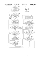
- FIG. 6 is a flow chart illustrating the operation of the repeater of the present invention.
- FIG. 7 is a diagram illustrating the transmission of information on two cable segments.
- FIG. 8 is a second embodiment of a system utilizing repeaters in accordance with the invention.
- repeaters 50, 52 are used to connect cable segment 54 to cable segment 56 thereby establishing a communication path for a plurality of stations 58 (numbered 1 to N).
- FIG. 5 illustrates one of repeaters 50, 52 in greater detail and comprises main controller 60 that controls the transmission of data between cable segments 54, 56.
- Encoder/decoders 66, 68 are connected directly to segments 54, 56, respectively and to a first in first out (FIFO) register 70.
- the system includes start of frame detectors 72, 74 and preamble and jam generators 76, 78.
- repeaters 71, 73, 75 and 77 are used to connect segments 70, 72, 74, and 76 in a ring configuration.
- the operation of a repeater connected between two cable segments in accordance with the present invention is illustrated by the flowchart of FIG. 6.
- the repeater is essentially always within one of three states: the repeat state; the standby state; or the fault state.
- the repeater is briefly in a reset state when first turned on or when deliberately reset, but quickly moves to standby.
- the repeater When first turned on, or when reset by an operator (box 100) the repeater moves to the standby state (box 102) and proceeds to monitor each of the two segments to which it is connected (referred to as "side A" and "side B") to detect the presence of "non-overlapping packets" of information (decision box 104).
- This is the repeater's method for detecting whether or not information is being independently repeated (e.g., by another repeater or repeaters) between side A and side B, and is accomplished due to the unique relationship between packets on two cable segments in a properly operating system.
- FIG. 7 illustrates this relationship, and depicts plots of the voltage on side A and side B when a packet is transmitted from side A to side B, versus time.
- the packets shown in FIG. 7 are illustrated by rectangular shaped voltage variations on the appropriate segment.
- the actual signal is basically a digital signal. However, for purposes of this discussion, the waveform is not important.
- the packets shown in the figure illustrate their time relationship.
- a packet 200 of length t 1 is transmitted on side A (e.g., by a station) and is received by a repeater and then transmitted on side B, with a delay t 2 caused by the time required for the repeater to receive, process and begin transmitting the packet. Since t 1 >t 2 for all possible transmissions (according to IEEE standards), the packets will always "overlap" each other. In other words, for every packet that is transmitted, the packet will simultaneously appear on both segments for a time equal to t 1 -t 2 . Therefore, if in the standby state a repeater "sees" overlapping packets of information, it will know that information is being properly repeated between the two segments and that, therefore, it should not enter the repeat state. Accordingly, if overlapping packets appear between side A and side B, the repeater will not see the required number (i.e., "N") of non-overlapping packets, and will, therefore, remain in the standby state.
- N required number
- the repeater In the repeat state, the repeater will repeat packets received at either segment to the other segment and will remain in this state unless collisions are encountered. If the repeater detects a predetermined number of collisions on either side A (decision box 108) or side B (decision box 110) the repeater will cease repeating received packets and will return to the standby state (boxes 112 and 126).
- the repeater will enter the standby state represented by box 112 and will cease all transmissions. Before testing for non-overlapping packets (as was done in decision box 104 above) the repeater waits until one packet is received on side A (the non-collision side) (decision box 114). The reason for this step will be explained below.
- step 120 the repeater leaves the standby state and enters the fault state (box 120).
- the repeater will attempt to send a packet to the fault side (side B in this example). If a packet is successfully sent, then the repeater returns to the repeat state (decision box 122) and will resume normal repeat operations. However, if a collision is again encountered the repeater will remain in the fault state and will continue to attempt to transmit a packet to the faulted side. After a predetermined number of attempts at transmitting a packet, the repeater will leave the fault state and return to standby (decision box 124).
- the repeater after reentering standby (box 112), waits until one packet is transmitted on side A (box 114). This step is necessary since it is possible that the original collisions that sent the repeater from the repeat state to the standby state (i.e., box 110) were caused by another (i.e., redundant) repeater. If this was the case, the two repeaters may both be in the fault state at the same time. Therefore, both repeaters will be trying to leave the fault state by transmitting a packet to side B, thereby causing more collisions, and yielding "no" results in box 122. Accordingly, the repeater will occasionally leave the fault state and let one packet arrive on side A to give another repeater a chance to return to the repeat state.
- the repeater Once the repeater has allowed a packet to be received on side A (thereby allowing a possible competing repeater to return to the repeat state), it will remain in the standby state (box 116) and check once again for non-overlapping packets. If the fault was originally caused by a redundant repeater, and that repeater has returned to the repeat state, the standby repeater will now see overlapping packets and remain in standby. If it sees the predetermined number of non-overlapping packets it will once again enter the fault state and attempt to return to the repeat state by trying once again to send a packet successfully to side B.
- a repeater operating in the repeat state (box 106) that encounters a predetermined number of collisions in its attempts to repeat packets to side B will stop repeating any information and enter the standby state (boxes 112, 116).
- the repeater checks to see if packets are already being properly repeated between the two segments (decision box 118). Only if it determines that packets are not being properly repeated (i.e., by seeing non-overlapping packets) does it try to send a packet to the faulted side (side B). If the repeater successfully sends a packet to the faulted side it returns to repeat (boxes 122, 106).
- the repeater After a predetermined number of attempts at sending a packet to side B, the repeater returns to standby in order to: (1) allow a competing repeater the opportunity to send a packet to side B without collisions (box 114); and (2) check and see if packets are being sent properly (box 118).
- Controller 60 comprises state machines that control the transition to the various states (i.e., repeat, fault, and standby) in accordance with the repeater operation described above.
- Encoder/decoders 66, 68 receive information from cable segments 54, 56 respectively and decode the received data to form digital packets of information. If the repeater is in the repeat state, the data is transmitted from, e.g., encoder/decoder 66 to FIFO 70, and then to encoder/decoder 68 and finally onto cable segment 56.
- Start of frame detector 72 informs controller 60 when a new packet is received on cable segment 54, enabling controller 60 to control the transmission of the packet onto cable segment 56.
- Preamble and jam generator 78 provides standard preamble data and jam signals for transmission onto cable segment 56. Packets received on cable segment 56 are similarly processed and transmitted using start of frame detector 74 and preamble and jam generator 76.
- controller 60 simply does not transmit packets received on either cable segment but watches for non-overlapping packets as discussed above. Similarly, when in fault state, transmission occurs only to the faulted cable segment.
- Both repeaters would return to standby from fault simultaneously (i.e., since "s” or "t” would be the same for both repeaters) and the repeaters would stay in this loop indefinitely. However, if all constants are different for redundantly connected repeaters, they cannot both travel through the loop together. Therefore, if two repeaters were both in the fault state, one would enter the standby state first (after reaching its "s” or "t” value) allowing the other repeater to successfully repeat a packet to the failed side thereby returning to the repeat state. The other repeater would then see overlapping packets and remain in standby.
- the constants Q, R, S and T should be different.
- the constants M, N and P may be equal to each other but may not be equal to Q, R, S or T.
- no single constant (M-T) on one repeater can equal the corresponding constant on the other repeater. If these conditions are met, the repeaters will never both remain in the standby or fault states. One repeater will always be able to return to the repeat state and reconnect the system. The other repeater will remain in standby until a failure occurs. It should be noted that it is not necessary to meet all of these conditions for proper operation of the repeaters. These conditions are optimal in order to resolve conflicts as quickly as possible.
- FIG. 8 illustrates a "ring network.”
- the network comprises four cable segments, 70, 72, 74 and 76.
- Four repeaters, 71, 73, 75 and 77, are used to connect the segments in a ring-shaped path.
- Each cable segment may include one or more stations (not shown).
- repeater 71 is in standby and the other repeaters are in repeat.
- a packet transmitted on segment 70 would be repeated to segment 76 by repeater 77.
- Repeater 75 would repeat the packet to segment 74 and repeater 73 would repeat the packet to segment 72.
- the packet has now been received by each segment without collision.
- repeaters of the present invention are connected in the arrangement of FIG. 8, three of the repeaters would always "settle" into the repeat state with the fourth remaining in standby. Which of the repeaters would be in standby would depend on the assigned values of the constants and on exactly when each of the repeaters is turned on and where the packets originate. As long as the rules regarding the values of the constants outlined above are followed, the network will always settle into a stable state with one repeater in standby.
Abstract
Description
Claims (30)
Priority Applications (1)
| Application Number | Priority Date | Filing Date | Title |
|---|---|---|---|
| US07/222,148 US4949340A (en) | 1988-07-21 | 1988-07-21 | Redundant repeater |
Applications Claiming Priority (1)
| Application Number | Priority Date | Filing Date | Title |
|---|---|---|---|
| US07/222,148 US4949340A (en) | 1988-07-21 | 1988-07-21 | Redundant repeater |
Publications (1)
| Publication Number | Publication Date |
|---|---|
| US4949340A true US4949340A (en) | 1990-08-14 |
Family
ID=22831060
Family Applications (1)
| Application Number | Title | Priority Date | Filing Date |
|---|---|---|---|
| US07/222,148 Expired - Fee Related US4949340A (en) | 1988-07-21 | 1988-07-21 | Redundant repeater |
Country Status (1)
| Country | Link |
|---|---|
| US (1) | US4949340A (en) |
Cited By (13)
| Publication number | Priority date | Publication date | Assignee | Title |
|---|---|---|---|---|
| US5257266A (en) * | 1991-02-27 | 1993-10-26 | General Dynamics Corporation, Space Systems Division | Computer and communications systems employing universal direct spherics processing architectures |
| WO1994000925A1 (en) * | 1992-06-26 | 1994-01-06 | Motorola Inc. | Fault tolerant radio communication system controller |
| GB2281178A (en) * | 1993-08-17 | 1995-02-22 | Nokia Telecommunications Oy | Repeater backup arrangement for securing operation of a telecommunications network in a cellular radio system |
| US5559883A (en) * | 1993-08-19 | 1996-09-24 | Chipcom Corporation | Method and apparatus for secure data packet bus communication |
| EP0762694A1 (en) * | 1995-09-01 | 1997-03-12 | Philips Patentverwaltung GmbH | Local Asynchronous Transfer Mode (ATM) network with at least two ring systems |
| US20030065974A1 (en) * | 2001-09-29 | 2003-04-03 | Lam An H. | Fault-tolerant switch architecture |
| US6564052B1 (en) * | 1999-03-19 | 2003-05-13 | Fujitsu Limited | Wireless local loop system and method for wireless link control |
| US6690916B1 (en) * | 2000-10-10 | 2004-02-10 | Motorola, Inc. | Radio network for radio communication in an enclosed environment and a repeater for such a radio network |
| US7415242B1 (en) * | 2003-11-10 | 2008-08-19 | Sprint Spectrum L.P. | Method and system for proximity detection for an in-building wireless repeater |
| US20110292863A1 (en) * | 2008-11-26 | 2011-12-01 | Oliver Braz | Single input single output repeater for relaying a multiple input multiple output signal |
| US9184962B2 (en) | 2009-12-09 | 2015-11-10 | Andrew Wireless Systems Gmbh | Distributed antenna system for MIMO signals |
| US9231670B2 (en) | 2010-10-01 | 2016-01-05 | Commscope Technologies Llc | Distributed antenna system for MIMO signals |
| US9413439B2 (en) | 2010-02-12 | 2016-08-09 | Commscope Technologies Llc | Distributed antenna system for MIMO communications |
Citations (6)
| Publication number | Priority date | Publication date | Assignee | Title |
|---|---|---|---|---|
| US2597043A (en) * | 1948-07-13 | 1952-05-20 | Int Standard Electric Corp | Automatic replacement of defective repeaters in high-frequency electric communication systems |
| US4039947A (en) * | 1976-06-29 | 1977-08-02 | Bell Telephone Laboratories, Incorporated | Protection switching system for microwave radio |
| US4406513A (en) * | 1981-03-11 | 1983-09-27 | Cermetek, Inc. | Optical repeater system having an automatic optical by-pass |
| US4581770A (en) * | 1983-12-19 | 1986-04-08 | Rca Corporation | Fail safe repeater for fiber optic bus distribution system |
| US4704713A (en) * | 1985-12-26 | 1987-11-03 | Bell Communications Research, Inc. | Optical ring network |
| US4727592A (en) * | 1984-07-25 | 1988-02-23 | Fujitsu Limited | Optical communication system |
-
1988
- 1988-07-21 US US07/222,148 patent/US4949340A/en not_active Expired - Fee Related
Patent Citations (6)
| Publication number | Priority date | Publication date | Assignee | Title |
|---|---|---|---|---|
| US2597043A (en) * | 1948-07-13 | 1952-05-20 | Int Standard Electric Corp | Automatic replacement of defective repeaters in high-frequency electric communication systems |
| US4039947A (en) * | 1976-06-29 | 1977-08-02 | Bell Telephone Laboratories, Incorporated | Protection switching system for microwave radio |
| US4406513A (en) * | 1981-03-11 | 1983-09-27 | Cermetek, Inc. | Optical repeater system having an automatic optical by-pass |
| US4581770A (en) * | 1983-12-19 | 1986-04-08 | Rca Corporation | Fail safe repeater for fiber optic bus distribution system |
| US4727592A (en) * | 1984-07-25 | 1988-02-23 | Fujitsu Limited | Optical communication system |
| US4704713A (en) * | 1985-12-26 | 1987-11-03 | Bell Communications Research, Inc. | Optical ring network |
Cited By (27)
| Publication number | Priority date | Publication date | Assignee | Title |
|---|---|---|---|---|
| US5257266A (en) * | 1991-02-27 | 1993-10-26 | General Dynamics Corporation, Space Systems Division | Computer and communications systems employing universal direct spherics processing architectures |
| WO1994000925A1 (en) * | 1992-06-26 | 1994-01-06 | Motorola Inc. | Fault tolerant radio communication system controller |
| US5530908A (en) * | 1992-06-26 | 1996-06-25 | Motorola, Inc. | Apparatus for providing fault tolerance in a radio communication system |
| GB2281178A (en) * | 1993-08-17 | 1995-02-22 | Nokia Telecommunications Oy | Repeater backup arrangement for securing operation of a telecommunications network in a cellular radio system |
| US5551056A (en) * | 1993-08-17 | 1996-08-27 | Nokia Telecommunications Oy | Method for securing the operation of a telecommunications network in a cellular radio system and a base station arrangement |
| GB2281178B (en) * | 1993-08-17 | 1997-08-13 | Nokia Telecommunications Oy | A method for securing the operation of a telecommunications network in a cellular radio system and a base station arrangement |
| US5559883A (en) * | 1993-08-19 | 1996-09-24 | Chipcom Corporation | Method and apparatus for secure data packet bus communication |
| EP0762694A1 (en) * | 1995-09-01 | 1997-03-12 | Philips Patentverwaltung GmbH | Local Asynchronous Transfer Mode (ATM) network with at least two ring systems |
| US6647429B1 (en) | 1995-09-01 | 2003-11-11 | Koninklijke Philips Electronics N.V. | Method and apparatus for interconnecting token ring lans operating in ATM |
| CN100361552C (en) * | 1999-03-19 | 2008-01-09 | 富士通株式会社 | Radio home loop system and radio chain circuit control method |
| US6564052B1 (en) * | 1999-03-19 | 2003-05-13 | Fujitsu Limited | Wireless local loop system and method for wireless link control |
| US6690916B1 (en) * | 2000-10-10 | 2004-02-10 | Motorola, Inc. | Radio network for radio communication in an enclosed environment and a repeater for such a radio network |
| US6925578B2 (en) * | 2001-09-29 | 2005-08-02 | Hewlett-Packard Development Company, L.P. | Fault-tolerant switch architecture |
| US20030065974A1 (en) * | 2001-09-29 | 2003-04-03 | Lam An H. | Fault-tolerant switch architecture |
| US10700754B2 (en) | 2001-11-30 | 2020-06-30 | Andrew Wireless Systems Gmbh | Distributed antenna system for MIMO signals |
| US7415242B1 (en) * | 2003-11-10 | 2008-08-19 | Sprint Spectrum L.P. | Method and system for proximity detection for an in-building wireless repeater |
| US20110292863A1 (en) * | 2008-11-26 | 2011-12-01 | Oliver Braz | Single input single output repeater for relaying a multiple input multiple output signal |
| US9787385B2 (en) | 2009-12-09 | 2017-10-10 | Andrew Wireless Systems Gmbh | Distributed antenna system for MIMO signals |
| US9246559B2 (en) | 2009-12-09 | 2016-01-26 | Andrew Wireless Systems Gmbh | Distributed antenna system for MIMO signals |
| US9184962B2 (en) | 2009-12-09 | 2015-11-10 | Andrew Wireless Systems Gmbh | Distributed antenna system for MIMO signals |
| US9413439B2 (en) | 2010-02-12 | 2016-08-09 | Commscope Technologies Llc | Distributed antenna system for MIMO communications |
| US9768840B2 (en) | 2010-02-12 | 2017-09-19 | Andrew Wireless Systems Gmbh | Distributed antenna system for MIMO communications |
| US10644761B2 (en) | 2010-02-12 | 2020-05-05 | Andrew Wireless Systems Gmbh | Distributed antenna system for MIMO communications |
| US9602176B2 (en) | 2010-10-01 | 2017-03-21 | Commscope Technologies Llc | Distributed antenna system for MIMO signals |
| US9231670B2 (en) | 2010-10-01 | 2016-01-05 | Commscope Technologies Llc | Distributed antenna system for MIMO signals |
| US9979443B2 (en) | 2010-10-01 | 2018-05-22 | Commscope Technologies Llc | Distributed antenna system for MIMO signals |
| US10491273B2 (en) | 2010-10-01 | 2019-11-26 | Commscope Technologies Llc | Distributed antenna system for MIMO signals |
Similar Documents
| Publication | Publication Date | Title |
|---|---|---|
| US5218600A (en) | Process for networking computers and/or computer networks and networking systems | |
| US4949340A (en) | Redundant repeater | |
| EP0755137B1 (en) | Hybrid network protocol with programmable assigned time slots and contention | |
| EP0102222B1 (en) | Loop transmission system and method of controlling its loop-back condition | |
| US4514843A (en) | Packet switched communication system comprising collision avoidance means | |
| US5115449A (en) | Data networks | |
| US5210632A (en) | Signal transmission system having a star coupled repeater | |
| US4747115A (en) | Bus-redundancy type apparatus for a transmitting system | |
| US5600657A (en) | Transmission path fault detecting method and system | |
| US4760488A (en) | Transmission control apparatus for duplex loop type transmission system | |
| JP3358801B2 (en) | Transmit burst reception monitor circuit | |
| JP2739532B2 (en) | Reconfiguration control method for token ring LAN system | |
| JP3015441B2 (en) | Private communication system | |
| JPS62150953A (en) | Method for detecting fault of loop transmission system | |
| JPS63296422A (en) | Detecting system for abnormal transmission state | |
| JPH0222947A (en) | Bypassing system for loop network | |
| JPS60106233A (en) | Transmission line switching device | |
| JPH01227544A (en) | Repeater | |
| JPH04183035A (en) | System for detecting transmission line fault | |
| JPH0445623A (en) | Control channel test system in multi-channel access radio communication system | |
| JPS60132442A (en) | Searching system for abnormal point of network | |
| JPS5923503B2 (en) | Loop transmission method | |
| JPS61296833A (en) | Time division bus communication system | |
| JPS60130941A (en) | Network of computer | |
| JPH0236635A (en) | Transmission control system for token bus network |
Legal Events
| Date | Code | Title | Description |
|---|---|---|---|
| AS | Assignment |
Owner name: XYPLEX, INC., MASSACHUSETTS Free format text: ASSIGNMENT OF ASSIGNORS INTEREST.;ASSIGNORS:SMITH, MARK L.;NICOSIA, JOSEPH J.;BOUDREAU, DANIEL A.;AND OTHERS;REEL/FRAME:005336/0802 Effective date: 19900529 |
|
| FEPP | Fee payment procedure |
Free format text: PAT HLDR NO LONGER CLAIMS SMALL ENT STAT AS SMALL BUSINESS (ORIGINAL EVENT CODE: LSM2); ENTITY STATUS OF PATENT OWNER: LARGE ENTITY Free format text: PAYOR NUMBER ASSIGNED (ORIGINAL EVENT CODE: ASPN); ENTITY STATUS OF PATENT OWNER: LARGE ENTITY |
|
| FPAY | Fee payment |
Year of fee payment: 4 |
|
| AS | Assignment |
Owner name: NATIONSBANK OF TEXAS, N.A., TEXAS Free format text: SECURITY INTEREST;ASSIGNORS:WHITTAKER CORPORATION;WHITTAKER COMMUNICATIONS, INC.;XYPLEX, INC.;REEL/FRAME:008119/0039 Effective date: 19960607 |
|
| REMI | Maintenance fee reminder mailed | ||
| FPAY | Fee payment |
Year of fee payment: 8 |
|
| SULP | Surcharge for late payment | ||
| AS | Assignment |
Owner name: WHITTAKER CORPORATION, CALIFORNIA Free format text: RELEASE OF SECURITY INTEREST;ASSIGNOR:BANK OF AMERICA, NATIONAL ASSOCIATION FORMERLY NATIONSBANK OF TEXAS, N.A.;REEL/FRAME:010188/0090 Effective date: 19990723 |
|
| REMI | Maintenance fee reminder mailed | ||
| LAPS | Lapse for failure to pay maintenance fees | ||
| STCH | Information on status: patent discontinuation |
Free format text: PATENT EXPIRED DUE TO NONPAYMENT OF MAINTENANCE FEES UNDER 37 CFR 1.362 |
|
| FP | Lapsed due to failure to pay maintenance fee |
Effective date: 20020814 |