US4949541A - Apparatus for the feed and the speed and torque control of a hydraulic motor with variable displacement at constant pressure - Google Patents
Apparatus for the feed and the speed and torque control of a hydraulic motor with variable displacement at constant pressure Download PDFInfo
- Publication number
- US4949541A US4949541A US07/160,688 US16068888A US4949541A US 4949541 A US4949541 A US 4949541A US 16068888 A US16068888 A US 16068888A US 4949541 A US4949541 A US 4949541A
- Authority
- US
- United States
- Prior art keywords
- motor
- hydraulic
- speed
- pressure
- feed
- Prior art date
- Legal status (The legal status is an assumption and is not a legal conclusion. Google has not performed a legal analysis and makes no representation as to the accuracy of the status listed.)
- Expired - Fee Related
Links
Images

Classifications
-
- B—PERFORMING OPERATIONS; TRANSPORTING
- B29—WORKING OF PLASTICS; WORKING OF SUBSTANCES IN A PLASTIC STATE IN GENERAL
- B29C—SHAPING OR JOINING OF PLASTICS; SHAPING OF MATERIAL IN A PLASTIC STATE, NOT OTHERWISE PROVIDED FOR; AFTER-TREATMENT OF THE SHAPED PRODUCTS, e.g. REPAIRING
- B29C45/00—Injection moulding, i.e. forcing the required volume of moulding material through a nozzle into a closed mould; Apparatus therefor
- B29C45/17—Component parts, details or accessories; Auxiliary operations
- B29C45/76—Measuring, controlling or regulating
- B29C45/82—Hydraulic or pneumatic circuits
-
- F—MECHANICAL ENGINEERING; LIGHTING; HEATING; WEAPONS; BLASTING
- F16—ENGINEERING ELEMENTS AND UNITS; GENERAL MEASURES FOR PRODUCING AND MAINTAINING EFFECTIVE FUNCTIONING OF MACHINES OR INSTALLATIONS; THERMAL INSULATION IN GENERAL
- F16H—GEARING
- F16H61/00—Control functions within control units of change-speed- or reversing-gearings for conveying rotary motion ; Control of exclusively fluid gearing, friction gearing, gearings with endless flexible members or other particular types of gearing
- F16H61/38—Control of exclusively fluid gearing
- F16H61/40—Control of exclusively fluid gearing hydrostatic
- F16H61/4078—Fluid exchange between hydrostatic circuits and external sources or consumers
- F16H61/4096—Fluid exchange between hydrostatic circuits and external sources or consumers with pressure accumulators
-
- F—MECHANICAL ENGINEERING; LIGHTING; HEATING; WEAPONS; BLASTING
- F16—ENGINEERING ELEMENTS AND UNITS; GENERAL MEASURES FOR PRODUCING AND MAINTAINING EFFECTIVE FUNCTIONING OF MACHINES OR INSTALLATIONS; THERMAL INSULATION IN GENERAL
- F16H—GEARING
- F16H61/00—Control functions within control units of change-speed- or reversing-gearings for conveying rotary motion ; Control of exclusively fluid gearing, friction gearing, gearings with endless flexible members or other particular types of gearing
- F16H61/38—Control of exclusively fluid gearing
- F16H61/40—Control of exclusively fluid gearing hydrostatic
- F16H61/4157—Control of braking, e.g. preventing pump over-speeding when motor acts as a pump
-
- F—MECHANICAL ENGINEERING; LIGHTING; HEATING; WEAPONS; BLASTING
- F16—ENGINEERING ELEMENTS AND UNITS; GENERAL MEASURES FOR PRODUCING AND MAINTAINING EFFECTIVE FUNCTIONING OF MACHINES OR INSTALLATIONS; THERMAL INSULATION IN GENERAL
- F16H—GEARING
- F16H61/00—Control functions within control units of change-speed- or reversing-gearings for conveying rotary motion ; Control of exclusively fluid gearing, friction gearing, gearings with endless flexible members or other particular types of gearing
- F16H61/38—Control of exclusively fluid gearing
- F16H61/40—Control of exclusively fluid gearing hydrostatic
- F16H61/42—Control of exclusively fluid gearing hydrostatic involving adjustment of a pump or motor with adjustable output or capacity
- F16H61/421—Motor capacity control by electro-hydraulic control means, e.g. using solenoid valves
-
- F—MECHANICAL ENGINEERING; LIGHTING; HEATING; WEAPONS; BLASTING
- F16—ENGINEERING ELEMENTS AND UNITS; GENERAL MEASURES FOR PRODUCING AND MAINTAINING EFFECTIVE FUNCTIONING OF MACHINES OR INSTALLATIONS; THERMAL INSULATION IN GENERAL
- F16H—GEARING
- F16H61/00—Control functions within control units of change-speed- or reversing-gearings for conveying rotary motion ; Control of exclusively fluid gearing, friction gearing, gearings with endless flexible members or other particular types of gearing
- F16H61/38—Control of exclusively fluid gearing
- F16H61/40—Control of exclusively fluid gearing hydrostatic
- F16H61/46—Automatic regulation in accordance with output requirements
- F16H61/472—Automatic regulation in accordance with output requirements for achieving a target output torque
-
- F—MECHANICAL ENGINEERING; LIGHTING; HEATING; WEAPONS; BLASTING
- F16—ENGINEERING ELEMENTS AND UNITS; GENERAL MEASURES FOR PRODUCING AND MAINTAINING EFFECTIVE FUNCTIONING OF MACHINES OR INSTALLATIONS; THERMAL INSULATION IN GENERAL
- F16H—GEARING
- F16H61/00—Control functions within control units of change-speed- or reversing-gearings for conveying rotary motion ; Control of exclusively fluid gearing, friction gearing, gearings with endless flexible members or other particular types of gearing
- F16H61/38—Control of exclusively fluid gearing
- F16H61/40—Control of exclusively fluid gearing hydrostatic
- F16H61/4148—Open loop circuits
Definitions
- the present invention relates to an apparatus for the feed and control of the speed of a hydraulic motor having variable swept volume, which enables variations in the resisting torque applied to the motor to be met, while the rotational speed is kept constant or is varied in accordance with the desired excursion.
- control or regulation must be carried out in a manner which reduces to a minimum the loss of energy, that is to say without the need to dump the feed when the latter is in excess, but appropriately controlling the behavior of the motor under all conditions.
- an apparatus for feed and control of the speed of a hydraulic motor having variable swept volume which comprises a hydraulic feed device for the motor adapted to supply the required flow rate of hydraulic fluid under all conditions at the working pressure, a constant pressure hydraulic control circuit associated with the hydraulic device or devices for varying the swept volume of the motor for modifying the swept volume itself in relation to the pressure of the hydraulic fluid supplied to the motor, and a flow regulating valve with proportional control, piloted by an electronic regulator generating a control signal for the valve and receiving the signal of a sensor of the rotational speed of the motor and a reference signal.
- the hydraulic feed device for the motor may be composed of a hydraulic pump with constant flow rate, associated with one or more hydropneumatic accumulators connected to the feed line to the motor, the pump being capable of supplying the mean value of flow rate required and the accumulators being capable of providing for temporary larger demands of hydraulic fluid by the motor, or, alternatively, of a pump having a variable swept volume, equipped with a regulator for pressure and delivery flow rate, adapted for keeping the delivery pressure constant and for supplying the flow rate required from time to time.
- the constant pressure regulator of the hydraulic device or devices for varying the swept volume of the motor is composed of a pressure reducing valve with fixed setting and of a piloted regulating valve with a line branched from the supply line to the motor, which valves are connected to the respective feed inlets of the device or devices for varying the swept volume of the motor.
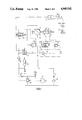
- FIG. 1 is a hydraulic diagram of the controller according to this invention, with a constant flow pump and hydropneumatic accumulator;
- FIG. 2 is a hydraulic diagram of the controller according to this invention, with a pump of variable delivery rate.
- FIG. 1 has a hydraulic motor 1 whose swept volume is variable by means of a hydraulic device 2, represented schematically.
- a displacement towards the right of the movable element 3 of the device 2 that is to say a feed at the inlet "x" produces a reduction in the swept volume.
- the motor is supplied from a constant delivery rate pump 4, via a flow regulating valve with proportional control 5.
- the position of the device 2 for varying the swept volume of the motor is controlled by a constant pressure regulator 6, comprising a regulating valve 7 and a pressure reducing valve 8, which react to variations in the supply pressure to the motor with a corresponding variation in the swept volume of the motor itself, varying in this manner the torque supplied by the motor and adjusting it to the demand of the external devices driven by it.
- the motor In feed pressure conditions lower than the value provided by the setting of the valve 7, the motor operates with the swept volume at a minimum; this comprises the maximum rotational speed of the motor and the minimum torque delivered.
- valve 7 piloted at its inlet 9, displaces progressively, bringing the motor 1 towards higher values of swept volume, thereby increasing the torque and reducing the speed, until equilibrium is reached with the feed pressure, as a function of the resistant torque applied to the motor.
- the rotational speed of the motor is monitored by a sensor 10 of the rotational speed of the motor shaft, the signal from which is of the electrical type and is supplied to an electronic regulator 11, where it is compared with a reference value 12, constituted of a suitable electrical signal.
- the electrical signal generated by the sensor 10 is a variable frequency signal and advantageously it is converted into a signal of variable current or variable voltage, by means of a frequency-current converter or frequency-voltage convertor 10a, enabling it to be compared with a signal 12 of the same type emitted by an appropriate function generator.
- the command produced by the controller 11 actuates the proportional-control flow regulating valve 5, by means of which the feed flow rate to the motor is modulated, until the desired value of speed is reached.
- one or more hydropneumatic accumulators 13 are provided, adapted for supplying for short periods the excess of fluid under pressure required by the valve 5, without the pump 4 having to have overdimensions for such conditions.
- the obturator 14, piloted by a controllable valve 15, enables starting and stopping of the motor to be controlled, and there are also provided filters 16, 17, 18, a dump valve 19 and non-return valves 20, 21, the functions of which are known and which are therefore not described in detail.
- a pump of variable delivery rate may be used, as illustrated in FIG. 2, in which like components have been given the same reference numerals as in FIG. 1.
- a hydraulic supply group 22 which comprises a variable-delivery pump 23, equipped with associated valves 24, 25 for controlling the delivery flow rate and pressure, and associated devices 26, 27 for regulating the swept volume, themselves of known type, controlled by the valves 24, 25.
- the pump 23 in the absence of hydropneumatic accumulators, the pump 23 must be designed to supply the maximum flow rate demanded by the motor; when this maximum flow rate is not required, the pump operates in conditions of reduced flow rate, thereby avoiding wastage of energy.
- the control apparatus therefore enables the conditions of rotational speed and torque necessary to be provided in every case, with the motor of variable swept volume, either by keeping said speed constant while varying the torque supplied, in response to the demands of the driven devices, or by following predetermined curves of speed variation in relation to the demand, such as, for example, for achieving a particular start-up or stopping ramp.
- This control may be carried out simply, by varying the reference signal 12 supplied to the regulator, which determines the position of the valve 5 on the basis of the rotational speed of the motor, because the flow rate determined by it and the torque required by the driven devices act in an autonomous manner, via the constant pressure regulator 6, upon the swept volume of the motor, adjusting it in all conditions to the required value, without the necessity for measuring the value of the effective swept volume in use at every instant in the motor itself.
Abstract
Description
Claims (3)
Applications Claiming Priority (1)
| Application Number | Priority Date | Filing Date | Title |
|---|---|---|---|
| EP88200347A EP0329860A1 (en) | 1988-02-25 | 1988-02-25 | Apparatus for the feed and the speed and torque control of a hydraulic motor with variable displacement at constant pressure |
Publications (1)
| Publication Number | Publication Date |
|---|---|
| US4949541A true US4949541A (en) | 1990-08-21 |
Family
ID=8199758
Family Applications (1)
| Application Number | Title | Priority Date | Filing Date |
|---|---|---|---|
| US07/160,688 Expired - Fee Related US4949541A (en) | 1988-02-25 | 1988-02-26 | Apparatus for the feed and the speed and torque control of a hydraulic motor with variable displacement at constant pressure |
Country Status (2)
| Country | Link |
|---|---|
| US (1) | US4949541A (en) |
| EP (1) | EP0329860A1 (en) |
Cited By (14)
| Publication number | Priority date | Publication date | Assignee | Title |
|---|---|---|---|---|
| US5042251A (en) * | 1987-09-03 | 1991-08-27 | Brueninghaushydraulik Gmbh | Secondary controlled hydrostatic driving gear having an open circuit |
| US5077975A (en) * | 1989-05-05 | 1992-01-07 | Mannesmann Rexroth Gmbh | Control for a load-dependently operating variable displacement pump |
| US5117634A (en) * | 1989-04-03 | 1992-06-02 | Paul Pleiger Maschinenfabrik Gmbh & Co. Kg | Apparatus for controlling the operation of hydraulic motors |
| US5226289A (en) * | 1990-08-13 | 1993-07-13 | Brueninghaus Hydraulik Gmbh | Control system for automatically regulating the displacement setting of a plurality of hydrostatic pumps |
| US5333997A (en) * | 1992-03-19 | 1994-08-02 | Hydromatik Gmbh | Device for the power control of at least two hydrostatic variable displacement pumps |
| US5438832A (en) * | 1992-08-31 | 1995-08-08 | Kayaba Industry Co., Ltd. | Variable displacement pump with adjustment responsive to drive motor speed |
| US20040177610A1 (en) * | 2003-03-11 | 2004-09-16 | Hendrickson Barry M. | Broad range speed control for hydraulic motors |
| US20060243518A1 (en) * | 2005-04-28 | 2006-11-02 | Jtekt Corporation | Hydraulic power steering unit |
| US20100307219A1 (en) * | 2009-06-08 | 2010-12-09 | Fackler Robert L | Method to calibrate a flow balance valve on a windrower draper header |
| US20110179781A1 (en) * | 2010-01-27 | 2011-07-28 | Charles Leon Fant | Hydraulic drive system for use in driven systems |
| US10495220B2 (en) | 2015-02-09 | 2019-12-03 | Uusi, Llc | Hydraulic control system for auxiliary power source |
| US10781770B2 (en) | 2017-12-19 | 2020-09-22 | Ibrahim Mounir Hanna | Cylinder system with relative motion occupying structure |
| US10788060B2 (en) | 2017-12-19 | 2020-09-29 | Ibrahim Mounir Hanna | Cylinder occupying structure |
| US11187321B2 (en) | 2015-02-09 | 2021-11-30 | Uusi, Llc | Control system for auxiliary power source |
Families Citing this family (4)
| Publication number | Priority date | Publication date | Assignee | Title |
|---|---|---|---|---|
| DE4000801C1 (en) * | 1990-01-12 | 1991-02-21 | Hydromatik Gmbh, 7915 Elchingen, De | |
| DE19601544C1 (en) * | 1996-01-17 | 1997-07-24 | Hydrokraft Gmbh | Flow controller |
| DE102012020632A1 (en) | 2012-10-19 | 2014-04-24 | Robert Bosch Gmbh | Method for driving hydraulic machine with variable displacement volume, involves reading reference value for displacement volume by using desired torque or desired volumetric flow rate at interface of hydraulic machine |
| CN104569817B (en) * | 2014-12-31 | 2017-08-01 | 北京理工大学 | A kind of hydraulic loaded motor performance test experimental system and its experimental method |
Citations (14)
| Publication number | Priority date | Publication date | Assignee | Title |
|---|---|---|---|---|
| US3296797A (en) * | 1964-07-15 | 1967-01-10 | Technometra Nardoni Podnik | Control device for hydrostatic pumps or motors |
| DE1811750A1 (en) * | 1968-11-29 | 1970-06-11 | Kloeckner Humboldt Deutz Ag | Hydrostatic power transmission device |
| GB1202673A (en) * | 1968-04-05 | 1970-08-19 | Alfred Fischbach | Hydraulic supply systems |
| US3866420A (en) * | 1972-07-22 | 1975-02-18 | Rexroth Gmbh G L | Hydraulic drive arrangement |
| US3965682A (en) * | 1973-07-20 | 1976-06-29 | Friedrich Kocks Gmbh | Hydraulic installation, more particularly for driving warping retaining winches on bulk cargo ships |
| US4011721A (en) * | 1976-04-14 | 1977-03-15 | Eaton Corporation | Fluid control system utilizing pressure drop valve |
| JPS57167501A (en) * | 1981-04-09 | 1982-10-15 | Daikin Ind Ltd | Control circuit of fluid |
| JPS608486A (en) * | 1983-06-27 | 1985-01-17 | Kawasaki Heavy Ind Ltd | Input horse power limiter for variable-volume pump |
| US4503674A (en) * | 1981-08-03 | 1985-03-12 | Linde Aktiengesellschaft | Hydrostatic drive systems |
| US4644748A (en) * | 1985-04-29 | 1987-02-24 | The Oilgear Company | Constant speed hydraulic drive |
| US4644749A (en) * | 1983-03-21 | 1987-02-24 | Sperry Corporation | Phase locked looped controller for motordrivers |
| US4710106A (en) * | 1984-11-26 | 1987-12-01 | Nippondenso Co., Ltd. | Volume controlling device for variable volume pump |
| US4712377A (en) * | 1984-09-17 | 1987-12-15 | Kabushiki Kaisha Komatsu Seisakusho | Control apparatus for hydraulic motor |
| US4736585A (en) * | 1985-03-15 | 1988-04-12 | Mannesmann Rexroth Gmbh | Hydrostatic machine |
Family Cites Families (4)
| Publication number | Priority date | Publication date | Assignee | Title |
|---|---|---|---|---|
| DE2739968A1 (en) * | 1977-09-06 | 1979-03-15 | Heinrich Prof Dr Ing Nikolaus | Hydrostatic transmission for motor vehicle - has hydraulic motor to power auxiliary reversible pump for control cylinder |
| US4399886A (en) * | 1980-12-09 | 1983-08-23 | Sundstrand Corporation | Controls for variable displacement motor and motors |
| DE3222008A1 (en) * | 1982-06-11 | 1983-12-15 | Sperry-Vickers Zweigniederlassung der Sperry GmbH, 6380 Bad Homburg | HYDROSTATIC OR PNEUMATIC DRIVE AND METHOD FOR ITS OPERATION |
| DE3537421A1 (en) * | 1985-10-21 | 1987-04-23 | Rexroth Mannesmann Gmbh | Plastics processing machine with hydraulic drives |
-
1988
- 1988-02-25 EP EP88200347A patent/EP0329860A1/en not_active Withdrawn
- 1988-02-26 US US07/160,688 patent/US4949541A/en not_active Expired - Fee Related
Patent Citations (14)
| Publication number | Priority date | Publication date | Assignee | Title |
|---|---|---|---|---|
| US3296797A (en) * | 1964-07-15 | 1967-01-10 | Technometra Nardoni Podnik | Control device for hydrostatic pumps or motors |
| GB1202673A (en) * | 1968-04-05 | 1970-08-19 | Alfred Fischbach | Hydraulic supply systems |
| DE1811750A1 (en) * | 1968-11-29 | 1970-06-11 | Kloeckner Humboldt Deutz Ag | Hydrostatic power transmission device |
| US3866420A (en) * | 1972-07-22 | 1975-02-18 | Rexroth Gmbh G L | Hydraulic drive arrangement |
| US3965682A (en) * | 1973-07-20 | 1976-06-29 | Friedrich Kocks Gmbh | Hydraulic installation, more particularly for driving warping retaining winches on bulk cargo ships |
| US4011721A (en) * | 1976-04-14 | 1977-03-15 | Eaton Corporation | Fluid control system utilizing pressure drop valve |
| JPS57167501A (en) * | 1981-04-09 | 1982-10-15 | Daikin Ind Ltd | Control circuit of fluid |
| US4503674A (en) * | 1981-08-03 | 1985-03-12 | Linde Aktiengesellschaft | Hydrostatic drive systems |
| US4644749A (en) * | 1983-03-21 | 1987-02-24 | Sperry Corporation | Phase locked looped controller for motordrivers |
| JPS608486A (en) * | 1983-06-27 | 1985-01-17 | Kawasaki Heavy Ind Ltd | Input horse power limiter for variable-volume pump |
| US4712377A (en) * | 1984-09-17 | 1987-12-15 | Kabushiki Kaisha Komatsu Seisakusho | Control apparatus for hydraulic motor |
| US4710106A (en) * | 1984-11-26 | 1987-12-01 | Nippondenso Co., Ltd. | Volume controlling device for variable volume pump |
| US4736585A (en) * | 1985-03-15 | 1988-04-12 | Mannesmann Rexroth Gmbh | Hydrostatic machine |
| US4644748A (en) * | 1985-04-29 | 1987-02-24 | The Oilgear Company | Constant speed hydraulic drive |
Cited By (16)
| Publication number | Priority date | Publication date | Assignee | Title |
|---|---|---|---|---|
| US5042251A (en) * | 1987-09-03 | 1991-08-27 | Brueninghaushydraulik Gmbh | Secondary controlled hydrostatic driving gear having an open circuit |
| US5117634A (en) * | 1989-04-03 | 1992-06-02 | Paul Pleiger Maschinenfabrik Gmbh & Co. Kg | Apparatus for controlling the operation of hydraulic motors |
| US5077975A (en) * | 1989-05-05 | 1992-01-07 | Mannesmann Rexroth Gmbh | Control for a load-dependently operating variable displacement pump |
| US5226289A (en) * | 1990-08-13 | 1993-07-13 | Brueninghaus Hydraulik Gmbh | Control system for automatically regulating the displacement setting of a plurality of hydrostatic pumps |
| US5333997A (en) * | 1992-03-19 | 1994-08-02 | Hydromatik Gmbh | Device for the power control of at least two hydrostatic variable displacement pumps |
| US5438832A (en) * | 1992-08-31 | 1995-08-08 | Kayaba Industry Co., Ltd. | Variable displacement pump with adjustment responsive to drive motor speed |
| US20040177610A1 (en) * | 2003-03-11 | 2004-09-16 | Hendrickson Barry M. | Broad range speed control for hydraulic motors |
| US8490742B2 (en) * | 2005-04-28 | 2013-07-23 | Jtekt Corporation | Hydraulic power steering unit |
| US20060243518A1 (en) * | 2005-04-28 | 2006-11-02 | Jtekt Corporation | Hydraulic power steering unit |
| US20100307219A1 (en) * | 2009-06-08 | 2010-12-09 | Fackler Robert L | Method to calibrate a flow balance valve on a windrower draper header |
| US8113033B2 (en) | 2009-06-08 | 2012-02-14 | Cnh America Llc | Method to calibrate a flow balance valve on a windrower draper header |
| US20110179781A1 (en) * | 2010-01-27 | 2011-07-28 | Charles Leon Fant | Hydraulic drive system for use in driven systems |
| US10495220B2 (en) | 2015-02-09 | 2019-12-03 | Uusi, Llc | Hydraulic control system for auxiliary power source |
| US11187321B2 (en) | 2015-02-09 | 2021-11-30 | Uusi, Llc | Control system for auxiliary power source |
| US10781770B2 (en) | 2017-12-19 | 2020-09-22 | Ibrahim Mounir Hanna | Cylinder system with relative motion occupying structure |
| US10788060B2 (en) | 2017-12-19 | 2020-09-29 | Ibrahim Mounir Hanna | Cylinder occupying structure |
Also Published As
| Publication number | Publication date |
|---|---|
| EP0329860A1 (en) | 1989-08-30 |
Similar Documents
| Publication | Publication Date | Title |
|---|---|---|
| US4949541A (en) | Apparatus for the feed and the speed and torque control of a hydraulic motor with variable displacement at constant pressure | |
| US4655688A (en) | Control for liquid ring vacuum pumps | |
| US5865602A (en) | Aircraft hydraulic pump control system | |
| US4180979A (en) | Anti-stall control for electrical hydrostatic transmission control system | |
| US5642716A (en) | Device for regulating the supply of pressurized fluid to a pressurized fluid accumulator, for example for motor vehicles | |
| US4428341A (en) | Electronic regulating device for rpm regulation in an internal combustion engine having self-ignition | |
| US20030138327A1 (en) | Speed control for a pumping system | |
| US4219000A (en) | Control device for selectable speeds in internal combustion engines | |
| JPH0311161B2 (en) | ||
| EP0404540B1 (en) | A system for controlling a pump apparatus | |
| US4708596A (en) | Device for regulating pressure and delivery of and adjustable pump | |
| JPS62240439A (en) | Driving device for hydraulic drive driven by diesel engine | |
| US5197859A (en) | Well pump system | |
| CA2133150C (en) | Hydraulic operational system for an injection molding machine | |
| US5341311A (en) | Method and apparatus for limiting the capacity of a hydrostatic machine | |
| US4134257A (en) | Gas turbine fuel delivery and control system | |
| US5117632A (en) | Method of operating a drive unit | |
| US4726187A (en) | Circuit arrangement for controlling the speed of rotation of a hydrostatic machine | |
| US5533867A (en) | Method and hydrostatic drive system for operating an adjustable hydrostatic pump | |
| US4688380A (en) | Control means for a drive system with impressed pressure | |
| US4475333A (en) | Devices for limiting the power output of a hydraulic assembly | |
| JPS59137218A (en) | Driving system | |
| US6344722B1 (en) | Control device for a membrane pump | |
| GB1462232A (en) | Apparatus including a regulation device for regulating the load driven by a prime mover | |
| SU846789A1 (en) | Pump unit operation mode automatic control system |
Legal Events
| Date | Code | Title | Description |
|---|---|---|---|
| AS | Assignment |
Owner name: RIVA CALZONI S.P.A., VIA STENDHAL 34, MILAN, ITALY Free format text: ASSIGNMENT OF ASSIGNORS INTEREST.;ASSIGNOR:DE VIETRO, IVANO;REEL/FRAME:004940/0450 Effective date: 19880218 Owner name: RIVA CALZONI S.P.A., A CORP. OF ITALY,ITALY Free format text: ASSIGNMENT OF ASSIGNORS INTEREST;ASSIGNOR:DE VIETRO, IVANO;REEL/FRAME:004940/0450 Effective date: 19880218 |
|
| REMI | Maintenance fee reminder mailed | ||
| LAPS | Lapse for failure to pay maintenance fees | ||
| FP | Lapsed due to failure to pay maintenance fee |
Effective date: 19940824 |
|
| STCH | Information on status: patent discontinuation |
Free format text: PATENT EXPIRED DUE TO NONPAYMENT OF MAINTENANCE FEES UNDER 37 CFR 1.362 |