US4954124A - Stand-up plastic bag and method of making same - Google Patents
Stand-up plastic bag and method of making same Download PDFInfo
- Publication number
- US4954124A US4954124A US07/303,310 US30331089A US4954124A US 4954124 A US4954124 A US 4954124A US 30331089 A US30331089 A US 30331089A US 4954124 A US4954124 A US 4954124A
- Authority
- US
- United States
- Prior art keywords
- walls
- bag
- heat
- side walls
- temperature range
- Prior art date
- Legal status (The legal status is an assumption and is not a legal conclusion. Google has not performed a legal analysis and makes no representation as to the accuracy of the status listed.)
- Expired - Fee Related
Links
Images


Classifications
-
- B—PERFORMING OPERATIONS; TRANSPORTING
- B65—CONVEYING; PACKING; STORING; HANDLING THIN OR FILAMENTARY MATERIAL
- B65D—CONTAINERS FOR STORAGE OR TRANSPORT OF ARTICLES OR MATERIALS, e.g. BAGS, BARRELS, BOTTLES, BOXES, CANS, CARTONS, CRATES, DRUMS, JARS, TANKS, HOPPERS, FORWARDING CONTAINERS; ACCESSORIES, CLOSURES, OR FITTINGS THEREFOR; PACKAGING ELEMENTS; PACKAGES
- B65D75/00—Packages comprising articles or materials partially or wholly enclosed in strips, sheets, blanks, tubes, or webs of flexible sheet material, e.g. in folded wrappers
- B65D75/008—Standing pouches, i.e. "Standbeutel"
-
- B—PERFORMING OPERATIONS; TRANSPORTING
- B29—WORKING OF PLASTICS; WORKING OF SUBSTANCES IN A PLASTIC STATE IN GENERAL
- B29C—SHAPING OR JOINING OF PLASTICS; SHAPING OF MATERIAL IN A PLASTIC STATE, NOT OTHERWISE PROVIDED FOR; AFTER-TREATMENT OF THE SHAPED PRODUCTS, e.g. REPAIRING
- B29C65/00—Joining or sealing of preformed parts, e.g. welding of plastics materials; Apparatus therefor
- B29C65/02—Joining or sealing of preformed parts, e.g. welding of plastics materials; Apparatus therefor by heating, with or without pressure
- B29C65/18—Joining or sealing of preformed parts, e.g. welding of plastics materials; Apparatus therefor by heating, with or without pressure using heated tools
-
- B—PERFORMING OPERATIONS; TRANSPORTING
- B29—WORKING OF PLASTICS; WORKING OF SUBSTANCES IN A PLASTIC STATE IN GENERAL
- B29C—SHAPING OR JOINING OF PLASTICS; SHAPING OF MATERIAL IN A PLASTIC STATE, NOT OTHERWISE PROVIDED FOR; AFTER-TREATMENT OF THE SHAPED PRODUCTS, e.g. REPAIRING
- B29C65/00—Joining or sealing of preformed parts, e.g. welding of plastics materials; Apparatus therefor
- B29C65/74—Joining or sealing of preformed parts, e.g. welding of plastics materials; Apparatus therefor by welding and severing, or by joining and severing, the severing being performed in the area to be joined, next to the area to be joined, in the joint area or next to the joint area
- B29C65/743—Joining or sealing of preformed parts, e.g. welding of plastics materials; Apparatus therefor by welding and severing, or by joining and severing, the severing being performed in the area to be joined, next to the area to be joined, in the joint area or next to the joint area using the same tool for both joining and severing, said tool being monobloc or formed by several parts mounted together and forming a monobloc
- B29C65/7437—Joining or sealing of preformed parts, e.g. welding of plastics materials; Apparatus therefor by welding and severing, or by joining and severing, the severing being performed in the area to be joined, next to the area to be joined, in the joint area or next to the joint area using the same tool for both joining and severing, said tool being monobloc or formed by several parts mounted together and forming a monobloc the tool being a perforating tool
-
- B—PERFORMING OPERATIONS; TRANSPORTING
- B29—WORKING OF PLASTICS; WORKING OF SUBSTANCES IN A PLASTIC STATE IN GENERAL
- B29C—SHAPING OR JOINING OF PLASTICS; SHAPING OF MATERIAL IN A PLASTIC STATE, NOT OTHERWISE PROVIDED FOR; AFTER-TREATMENT OF THE SHAPED PRODUCTS, e.g. REPAIRING
- B29C66/00—General aspects of processes or apparatus for joining preformed parts
- B29C66/01—General aspects dealing with the joint area or with the area to be joined
- B29C66/05—Particular design of joint configurations
- B29C66/10—Particular design of joint configurations particular design of the joint cross-sections
- B29C66/11—Joint cross-sections comprising a single joint-segment, i.e. one of the parts to be joined comprising a single joint-segment in the joint cross-section
- B29C66/112—Single lapped joints
- B29C66/1122—Single lap to lap joints, i.e. overlap joints
-
- B—PERFORMING OPERATIONS; TRANSPORTING
- B29—WORKING OF PLASTICS; WORKING OF SUBSTANCES IN A PLASTIC STATE IN GENERAL
- B29C—SHAPING OR JOINING OF PLASTICS; SHAPING OF MATERIAL IN A PLASTIC STATE, NOT OTHERWISE PROVIDED FOR; AFTER-TREATMENT OF THE SHAPED PRODUCTS, e.g. REPAIRING
- B29C66/00—General aspects of processes or apparatus for joining preformed parts
- B29C66/01—General aspects dealing with the joint area or with the area to be joined
- B29C66/05—Particular design of joint configurations
- B29C66/10—Particular design of joint configurations particular design of the joint cross-sections
- B29C66/13—Single flanged joints; Fin-type joints; Single hem joints; Edge joints; Interpenetrating fingered joints; Other specific particular designs of joint cross-sections not provided for in groups B29C66/11 - B29C66/12
- B29C66/135—Single hemmed joints, i.e. one of the parts to be joined being hemmed in the joint area
-
- B—PERFORMING OPERATIONS; TRANSPORTING
- B29—WORKING OF PLASTICS; WORKING OF SUBSTANCES IN A PLASTIC STATE IN GENERAL
- B29C—SHAPING OR JOINING OF PLASTICS; SHAPING OF MATERIAL IN A PLASTIC STATE, NOT OTHERWISE PROVIDED FOR; AFTER-TREATMENT OF THE SHAPED PRODUCTS, e.g. REPAIRING
- B29C66/00—General aspects of processes or apparatus for joining preformed parts
- B29C66/01—General aspects dealing with the joint area or with the area to be joined
- B29C66/05—Particular design of joint configurations
- B29C66/20—Particular design of joint configurations particular design of the joint lines, e.g. of the weld lines
- B29C66/24—Particular design of joint configurations particular design of the joint lines, e.g. of the weld lines said joint lines being closed or non-straight
- B29C66/244—Particular design of joint configurations particular design of the joint lines, e.g. of the weld lines said joint lines being closed or non-straight said joint lines being non-straight, e.g. forming non-closed contours
-
- B—PERFORMING OPERATIONS; TRANSPORTING
- B29—WORKING OF PLASTICS; WORKING OF SUBSTANCES IN A PLASTIC STATE IN GENERAL
- B29C—SHAPING OR JOINING OF PLASTICS; SHAPING OF MATERIAL IN A PLASTIC STATE, NOT OTHERWISE PROVIDED FOR; AFTER-TREATMENT OF THE SHAPED PRODUCTS, e.g. REPAIRING
- B29C66/00—General aspects of processes or apparatus for joining preformed parts
- B29C66/40—General aspects of joining substantially flat articles, e.g. plates, sheets or web-like materials; Making flat seams in tubular or hollow articles; Joining single elements to substantially flat surfaces
- B29C66/41—Joining substantially flat articles ; Making flat seams in tubular or hollow articles
- B29C66/43—Joining a relatively small portion of the surface of said articles
- B29C66/431—Joining the articles to themselves
- B29C66/4312—Joining the articles to themselves for making flat seams in tubular or hollow articles, e.g. transversal seams
- B29C66/43129—Joining the articles to themselves for making flat seams in tubular or hollow articles, e.g. transversal seams said flat seams being transversal but non-orthogonal with respect to the tubular or hollow articles, i.e. oblique
-
- B—PERFORMING OPERATIONS; TRANSPORTING
- B29—WORKING OF PLASTICS; WORKING OF SUBSTANCES IN A PLASTIC STATE IN GENERAL
- B29C—SHAPING OR JOINING OF PLASTICS; SHAPING OF MATERIAL IN A PLASTIC STATE, NOT OTHERWISE PROVIDED FOR; AFTER-TREATMENT OF THE SHAPED PRODUCTS, e.g. REPAIRING
- B29C66/00—General aspects of processes or apparatus for joining preformed parts
- B29C66/70—General aspects of processes or apparatus for joining preformed parts characterised by the composition, physical properties or the structure of the material of the parts to be joined; Joining with non-plastics material
- B29C66/72—General aspects of processes or apparatus for joining preformed parts characterised by the composition, physical properties or the structure of the material of the parts to be joined; Joining with non-plastics material characterised by the structure of the material of the parts to be joined
- B29C66/723—General aspects of processes or apparatus for joining preformed parts characterised by the composition, physical properties or the structure of the material of the parts to be joined; Joining with non-plastics material characterised by the structure of the material of the parts to be joined being multi-layered
- B29C66/7234—General aspects of processes or apparatus for joining preformed parts characterised by the composition, physical properties or the structure of the material of the parts to be joined; Joining with non-plastics material characterised by the structure of the material of the parts to be joined being multi-layered comprising a barrier layer
- B29C66/72343—General aspects of processes or apparatus for joining preformed parts characterised by the composition, physical properties or the structure of the material of the parts to be joined; Joining with non-plastics material characterised by the structure of the material of the parts to be joined being multi-layered comprising a barrier layer for liquids
-
- B—PERFORMING OPERATIONS; TRANSPORTING
- B29—WORKING OF PLASTICS; WORKING OF SUBSTANCES IN A PLASTIC STATE IN GENERAL
- B29C—SHAPING OR JOINING OF PLASTICS; SHAPING OF MATERIAL IN A PLASTIC STATE, NOT OTHERWISE PROVIDED FOR; AFTER-TREATMENT OF THE SHAPED PRODUCTS, e.g. REPAIRING
- B29C66/00—General aspects of processes or apparatus for joining preformed parts
- B29C66/70—General aspects of processes or apparatus for joining preformed parts characterised by the composition, physical properties or the structure of the material of the parts to be joined; Joining with non-plastics material
- B29C66/73—General aspects of processes or apparatus for joining preformed parts characterised by the composition, physical properties or the structure of the material of the parts to be joined; Joining with non-plastics material characterised by the intensive physical properties of the material of the parts to be joined, by the optical properties of the material of the parts to be joined, by the extensive physical properties of the parts to be joined, by the state of the material of the parts to be joined or by the material of the parts to be joined being a thermoplastic or a thermoset
- B29C66/739—General aspects of processes or apparatus for joining preformed parts characterised by the composition, physical properties or the structure of the material of the parts to be joined; Joining with non-plastics material characterised by the intensive physical properties of the material of the parts to be joined, by the optical properties of the material of the parts to be joined, by the extensive physical properties of the parts to be joined, by the state of the material of the parts to be joined or by the material of the parts to be joined being a thermoplastic or a thermoset characterised by the material of the parts to be joined being a thermoplastic or a thermoset
- B29C66/7392—General aspects of processes or apparatus for joining preformed parts characterised by the composition, physical properties or the structure of the material of the parts to be joined; Joining with non-plastics material characterised by the intensive physical properties of the material of the parts to be joined, by the optical properties of the material of the parts to be joined, by the extensive physical properties of the parts to be joined, by the state of the material of the parts to be joined or by the material of the parts to be joined being a thermoplastic or a thermoset characterised by the material of the parts to be joined being a thermoplastic or a thermoset characterised by the material of at least one of the parts being a thermoplastic
- B29C66/73921—General aspects of processes or apparatus for joining preformed parts characterised by the composition, physical properties or the structure of the material of the parts to be joined; Joining with non-plastics material characterised by the intensive physical properties of the material of the parts to be joined, by the optical properties of the material of the parts to be joined, by the extensive physical properties of the parts to be joined, by the state of the material of the parts to be joined or by the material of the parts to be joined being a thermoplastic or a thermoset characterised by the material of the parts to be joined being a thermoplastic or a thermoset characterised by the material of at least one of the parts being a thermoplastic characterised by the materials of both parts being thermoplastics
-
- B—PERFORMING OPERATIONS; TRANSPORTING
- B29—WORKING OF PLASTICS; WORKING OF SUBSTANCES IN A PLASTIC STATE IN GENERAL
- B29C—SHAPING OR JOINING OF PLASTICS; SHAPING OF MATERIAL IN A PLASTIC STATE, NOT OTHERWISE PROVIDED FOR; AFTER-TREATMENT OF THE SHAPED PRODUCTS, e.g. REPAIRING
- B29C66/00—General aspects of processes or apparatus for joining preformed parts
- B29C66/90—Measuring or controlling the joining process
- B29C66/91—Measuring or controlling the joining process by measuring or controlling the temperature, the heat or the thermal flux
- B29C66/914—Measuring or controlling the joining process by measuring or controlling the temperature, the heat or the thermal flux by controlling or regulating the temperature, the heat or the thermal flux
- B29C66/9141—Measuring or controlling the joining process by measuring or controlling the temperature, the heat or the thermal flux by controlling or regulating the temperature, the heat or the thermal flux by controlling or regulating the temperature
- B29C66/91411—Measuring or controlling the joining process by measuring or controlling the temperature, the heat or the thermal flux by controlling or regulating the temperature, the heat or the thermal flux by controlling or regulating the temperature of the parts to be joined, e.g. the joining process taking the temperature of the parts to be joined into account
-
- B—PERFORMING OPERATIONS; TRANSPORTING
- B29—WORKING OF PLASTICS; WORKING OF SUBSTANCES IN A PLASTIC STATE IN GENERAL
- B29C—SHAPING OR JOINING OF PLASTICS; SHAPING OF MATERIAL IN A PLASTIC STATE, NOT OTHERWISE PROVIDED FOR; AFTER-TREATMENT OF THE SHAPED PRODUCTS, e.g. REPAIRING
- B29C66/00—General aspects of processes or apparatus for joining preformed parts
- B29C66/90—Measuring or controlling the joining process
- B29C66/91—Measuring or controlling the joining process by measuring or controlling the temperature, the heat or the thermal flux
- B29C66/919—Measuring or controlling the joining process by measuring or controlling the temperature, the heat or the thermal flux characterised by specific temperature, heat or thermal flux values or ranges
- B29C66/9192—Measuring or controlling the joining process by measuring or controlling the temperature, the heat or the thermal flux characterised by specific temperature, heat or thermal flux values or ranges in explicit relation to another variable, e.g. temperature diagrams
- B29C66/91921—Measuring or controlling the joining process by measuring or controlling the temperature, the heat or the thermal flux characterised by specific temperature, heat or thermal flux values or ranges in explicit relation to another variable, e.g. temperature diagrams in explicit relation to another temperature, e.g. to the softening temperature or softening point, to the thermal degradation temperature or to the ambient temperature
- B29C66/91931—Measuring or controlling the joining process by measuring or controlling the temperature, the heat or the thermal flux characterised by specific temperature, heat or thermal flux values or ranges in explicit relation to another variable, e.g. temperature diagrams in explicit relation to another temperature, e.g. to the softening temperature or softening point, to the thermal degradation temperature or to the ambient temperature in explicit relation to the fusion temperature or melting point of the material of one of the parts to be joined
-
- B—PERFORMING OPERATIONS; TRANSPORTING
- B65—CONVEYING; PACKING; STORING; HANDLING THIN OR FILAMENTARY MATERIAL
- B65D—CONTAINERS FOR STORAGE OR TRANSPORT OF ARTICLES OR MATERIALS, e.g. BAGS, BARRELS, BOTTLES, BOXES, CANS, CARTONS, CRATES, DRUMS, JARS, TANKS, HOPPERS, FORWARDING CONTAINERS; ACCESSORIES, CLOSURES, OR FITTINGS THEREFOR; PACKAGING ELEMENTS; PACKAGES
- B65D33/00—Details of, or accessories for, sacks or bags
- B65D33/16—End- or aperture-closing arrangements or devices
- B65D33/25—Riveting; Dovetailing; Screwing; using press buttons or slide fasteners
- B65D33/2508—Riveting; Dovetailing; Screwing; using press buttons or slide fasteners using slide fasteners with interlocking members having a substantially uniform section throughout the length of the fastener; Sliders therefor
-
- B—PERFORMING OPERATIONS; TRANSPORTING
- B29—WORKING OF PLASTICS; WORKING OF SUBSTANCES IN A PLASTIC STATE IN GENERAL
- B29C—SHAPING OR JOINING OF PLASTICS; SHAPING OF MATERIAL IN A PLASTIC STATE, NOT OTHERWISE PROVIDED FOR; AFTER-TREATMENT OF THE SHAPED PRODUCTS, e.g. REPAIRING
- B29C65/00—Joining or sealing of preformed parts, e.g. welding of plastics materials; Apparatus therefor
- B29C65/02—Joining or sealing of preformed parts, e.g. welding of plastics materials; Apparatus therefor by heating, with or without pressure
- B29C65/18—Joining or sealing of preformed parts, e.g. welding of plastics materials; Apparatus therefor by heating, with or without pressure using heated tools
- B29C65/22—Heated wire resistive ribbon, resistive band or resistive strip
- B29C65/221—Heated wire resistive ribbon, resistive band or resistive strip characterised by the type of heated wire, resistive ribbon, band or strip
- B29C65/222—Heated wire resistive ribbon, resistive band or resistive strip characterised by the type of heated wire, resistive ribbon, band or strip comprising at least a single heated wire
-
- B—PERFORMING OPERATIONS; TRANSPORTING
- B29—WORKING OF PLASTICS; WORKING OF SUBSTANCES IN A PLASTIC STATE IN GENERAL
- B29C—SHAPING OR JOINING OF PLASTICS; SHAPING OF MATERIAL IN A PLASTIC STATE, NOT OTHERWISE PROVIDED FOR; AFTER-TREATMENT OF THE SHAPED PRODUCTS, e.g. REPAIRING
- B29C66/00—General aspects of processes or apparatus for joining preformed parts
- B29C66/70—General aspects of processes or apparatus for joining preformed parts characterised by the composition, physical properties or the structure of the material of the parts to be joined; Joining with non-plastics material
- B29C66/71—General aspects of processes or apparatus for joining preformed parts characterised by the composition, physical properties or the structure of the material of the parts to be joined; Joining with non-plastics material characterised by the composition of the plastics material of the parts to be joined
-
- B—PERFORMING OPERATIONS; TRANSPORTING
- B29—WORKING OF PLASTICS; WORKING OF SUBSTANCES IN A PLASTIC STATE IN GENERAL
- B29C—SHAPING OR JOINING OF PLASTICS; SHAPING OF MATERIAL IN A PLASTIC STATE, NOT OTHERWISE PROVIDED FOR; AFTER-TREATMENT OF THE SHAPED PRODUCTS, e.g. REPAIRING
- B29C66/00—General aspects of processes or apparatus for joining preformed parts
- B29C66/90—Measuring or controlling the joining process
- B29C66/91—Measuring or controlling the joining process by measuring or controlling the temperature, the heat or the thermal flux
- B29C66/914—Measuring or controlling the joining process by measuring or controlling the temperature, the heat or the thermal flux by controlling or regulating the temperature, the heat or the thermal flux
- B29C66/9161—Measuring or controlling the joining process by measuring or controlling the temperature, the heat or the thermal flux by controlling or regulating the temperature, the heat or the thermal flux by controlling or regulating the heat or the thermal flux, i.e. the heat flux
- B29C66/91641—Measuring or controlling the joining process by measuring or controlling the temperature, the heat or the thermal flux by controlling or regulating the temperature, the heat or the thermal flux by controlling or regulating the heat or the thermal flux, i.e. the heat flux the heat or the thermal flux being non-constant over time
- B29C66/91643—Measuring or controlling the joining process by measuring or controlling the temperature, the heat or the thermal flux by controlling or regulating the temperature, the heat or the thermal flux by controlling or regulating the heat or the thermal flux, i.e. the heat flux the heat or the thermal flux being non-constant over time following a heat-time profile
- B29C66/91645—Measuring or controlling the joining process by measuring or controlling the temperature, the heat or the thermal flux by controlling or regulating the temperature, the heat or the thermal flux by controlling or regulating the heat or the thermal flux, i.e. the heat flux the heat or the thermal flux being non-constant over time following a heat-time profile by steps
-
- B—PERFORMING OPERATIONS; TRANSPORTING
- B29—WORKING OF PLASTICS; WORKING OF SUBSTANCES IN A PLASTIC STATE IN GENERAL
- B29C—SHAPING OR JOINING OF PLASTICS; SHAPING OF MATERIAL IN A PLASTIC STATE, NOT OTHERWISE PROVIDED FOR; AFTER-TREATMENT OF THE SHAPED PRODUCTS, e.g. REPAIRING
- B29C66/00—General aspects of processes or apparatus for joining preformed parts
- B29C66/90—Measuring or controlling the joining process
- B29C66/91—Measuring or controlling the joining process by measuring or controlling the temperature, the heat or the thermal flux
- B29C66/919—Measuring or controlling the joining process by measuring or controlling the temperature, the heat or the thermal flux characterised by specific temperature, heat or thermal flux values or ranges
- B29C66/9192—Measuring or controlling the joining process by measuring or controlling the temperature, the heat or the thermal flux characterised by specific temperature, heat or thermal flux values or ranges in explicit relation to another variable, e.g. temperature diagrams
- B29C66/91921—Measuring or controlling the joining process by measuring or controlling the temperature, the heat or the thermal flux characterised by specific temperature, heat or thermal flux values or ranges in explicit relation to another variable, e.g. temperature diagrams in explicit relation to another temperature, e.g. to the softening temperature or softening point, to the thermal degradation temperature or to the ambient temperature
- B29C66/91931—Measuring or controlling the joining process by measuring or controlling the temperature, the heat or the thermal flux characterised by specific temperature, heat or thermal flux values or ranges in explicit relation to another variable, e.g. temperature diagrams in explicit relation to another temperature, e.g. to the softening temperature or softening point, to the thermal degradation temperature or to the ambient temperature in explicit relation to the fusion temperature or melting point of the material of one of the parts to be joined
- B29C66/91933—Measuring or controlling the joining process by measuring or controlling the temperature, the heat or the thermal flux characterised by specific temperature, heat or thermal flux values or ranges in explicit relation to another variable, e.g. temperature diagrams in explicit relation to another temperature, e.g. to the softening temperature or softening point, to the thermal degradation temperature or to the ambient temperature in explicit relation to the fusion temperature or melting point of the material of one of the parts to be joined higher than said fusion temperature
-
- B—PERFORMING OPERATIONS; TRANSPORTING
- B29—WORKING OF PLASTICS; WORKING OF SUBSTANCES IN A PLASTIC STATE IN GENERAL
- B29C—SHAPING OR JOINING OF PLASTICS; SHAPING OF MATERIAL IN A PLASTIC STATE, NOT OTHERWISE PROVIDED FOR; AFTER-TREATMENT OF THE SHAPED PRODUCTS, e.g. REPAIRING
- B29C66/00—General aspects of processes or apparatus for joining preformed parts
- B29C66/90—Measuring or controlling the joining process
- B29C66/91—Measuring or controlling the joining process by measuring or controlling the temperature, the heat or the thermal flux
- B29C66/919—Measuring or controlling the joining process by measuring or controlling the temperature, the heat or the thermal flux characterised by specific temperature, heat or thermal flux values or ranges
- B29C66/9192—Measuring or controlling the joining process by measuring or controlling the temperature, the heat or the thermal flux characterised by specific temperature, heat or thermal flux values or ranges in explicit relation to another variable, e.g. temperature diagrams
- B29C66/91921—Measuring or controlling the joining process by measuring or controlling the temperature, the heat or the thermal flux characterised by specific temperature, heat or thermal flux values or ranges in explicit relation to another variable, e.g. temperature diagrams in explicit relation to another temperature, e.g. to the softening temperature or softening point, to the thermal degradation temperature or to the ambient temperature
- B29C66/91931—Measuring or controlling the joining process by measuring or controlling the temperature, the heat or the thermal flux characterised by specific temperature, heat or thermal flux values or ranges in explicit relation to another variable, e.g. temperature diagrams in explicit relation to another temperature, e.g. to the softening temperature or softening point, to the thermal degradation temperature or to the ambient temperature in explicit relation to the fusion temperature or melting point of the material of one of the parts to be joined
- B29C66/91935—Measuring or controlling the joining process by measuring or controlling the temperature, the heat or the thermal flux characterised by specific temperature, heat or thermal flux values or ranges in explicit relation to another variable, e.g. temperature diagrams in explicit relation to another temperature, e.g. to the softening temperature or softening point, to the thermal degradation temperature or to the ambient temperature in explicit relation to the fusion temperature or melting point of the material of one of the parts to be joined lower than said fusion temperature
-
- B—PERFORMING OPERATIONS; TRANSPORTING
- B31—MAKING ARTICLES OF PAPER, CARDBOARD OR MATERIAL WORKED IN A MANNER ANALOGOUS TO PAPER; WORKING PAPER, CARDBOARD OR MATERIAL WORKED IN A MANNER ANALOGOUS TO PAPER
- B31B—MAKING CONTAINERS OF PAPER, CARDBOARD OR MATERIAL WORKED IN A MANNER ANALOGOUS TO PAPER
- B31B2155/00—Flexible containers made from webs
-
- B—PERFORMING OPERATIONS; TRANSPORTING
- B31—MAKING ARTICLES OF PAPER, CARDBOARD OR MATERIAL WORKED IN A MANNER ANALOGOUS TO PAPER; WORKING PAPER, CARDBOARD OR MATERIAL WORKED IN A MANNER ANALOGOUS TO PAPER
- B31B—MAKING CONTAINERS OF PAPER, CARDBOARD OR MATERIAL WORKED IN A MANNER ANALOGOUS TO PAPER
- B31B2160/00—Shape of flexible containers
- B31B2160/20—Shape of flexible containers with structural provision for thickness of contents
-
- B—PERFORMING OPERATIONS; TRANSPORTING
- B31—MAKING ARTICLES OF PAPER, CARDBOARD OR MATERIAL WORKED IN A MANNER ANALOGOUS TO PAPER; WORKING PAPER, CARDBOARD OR MATERIAL WORKED IN A MANNER ANALOGOUS TO PAPER
- B31B—MAKING CONTAINERS OF PAPER, CARDBOARD OR MATERIAL WORKED IN A MANNER ANALOGOUS TO PAPER
- B31B2170/00—Construction of flexible containers
- B31B2170/20—Construction of flexible containers having multi-layered walls, e.g. laminated or lined
Definitions
- the present invention generally relates to plastic bags and, more particularly, to a plastic bag capable of standing up by itself before, during and after being filled and to a method making the bag.
- plastic bags So-called stand-up, free-standing or self-standing plastic bags are well-known in the prior art. Representative of the prior art are the plastic bags disclosed in U.S. Pat. Nos. to Knuetter (2,265,075), Doyen et al (3,380,646), Kugler (3,437,258), Michel (3,715,074) and Bustin (4,353,497). Also, well-known in the prior art are plastic bags incorporating a zipper-type closure device along the top opening or mouth of the bags. Representative of the prior art are the plastic bags disclosed in a U.S. Pat. No. to Ausnit (4,601,694) and a U.K. Patent Application to Kirkpatrick (2,047,199). Further, U.S. Pat. Nos. to Kan (3,980,225 and 4,055,109) disclose a self-standing plastic bag which also incorporates a zipper-type closure device along its mouth.
- Some known stand-up bags attempt to provide the stand-up capability merely by use of a simple bottom gusset alone or supplemented with seals added in the gusset structure.
- a simple bottom gusset sealed at its sides does not provide a normal consumer plastic bag with a sufficient stand-up feature.
- Such plastic bag typically made from polyethylene film, for example of under 1.0 mil thickness, is too limp to stand up from the gusseted bottom.
- plastic films of greater thickness and higher modulus can be fabricated into a bag that will stand up from a simple bottom gusset.
- One plastic bag currently available uses a very deep bottom gusset design to provide certain advantages in food storage and microwave heating, but some difficulty has been experienced in filling and emptying this bag. The bag does not stand up easily when empty, and the zipper-type closure is difficult to maintain open when filling and emptying this bag.
- Other currently-available stand-up bags seal the bottom gusset into a stand-up base that is much more stable than the simple bottom gusset.
- the self-standing bag of the above-cited U.S. patents to Kan is an example of a bag having such stand-up base.
- the present invention provides a stand-up plastic bag and method of making same designed to satisfy the aforementioned needs.
- the stand-up plastic bag of the present invention comprises a pair of front and rear side walls which define an open mouth at upper edges of the side walls, and a pair of front and rear bottom gusset walls disposed between the side walls.
- the front and rear side walls and the front and rear bottom gusset walls are composed of a multi-layered film of first and second heat-sealable thermoplastic materials.
- the first material is on interior surfaces of the walls and heat-sealable at a temperature within a first temperature range.
- the second material is on exterior surfaces of walls and heat-sealable at a temperature within a second temperature range greater than the first temperature range.
- the bottom gusset walls have upper portions that are interconnected together to define a bottom wall extending between the front and rear side walls.
- the bottom gusset walls also have lower portions joined by heat seals to lower portions of the front and rear side walls at contiguous portions of the first material on the interior surfaces thereof to form a support band connected to and extending below the periphery of the bottom wall.
- the bottom gusset walls further have opposite longitudinal edges joined together by heat seals at contiguous portions of the second material on the exterior surfaces thereof which complete formation of the support band as a continuous self-standing structure and define with the bottom wall a stand-up base on the bag.
- front and rear side walls and the front and rear bottom gusset walls along opposite longitudinal edges of the walls are joined together by heat seals at contiguous portions of the first material on interior surfaces thereof.
- an openable and closable closure device is defined on the front and rear side walls below and adjacent to the bag mouth defined at the upper edges of the side walls.
- the method of the present invention for making the stand-up plastic bag comprises the steps of: supplying a multi-layered film of the first and second heat-sealable thermoplastic materials; folding the film to form the front and rear side walls and the front and rear bottom gusset walls disposed between the side walls with interior surfaces of the walls having the first material thereon and exterior surfaces of the walls having the second material thereon; forming heat seals which join lower portions of the front and rear bottom gusset walls with corresponding lower portions of the front and rear side walls at contiguous regions of the first material on the interior surfaces thereof and thereby form a support band being connected to and extending below the periphery of a bottom wall formed by connected upper portions of the front and rear bottom gusset walls which extend between the front and rear side walls; forming heat seals which join the front and rear side walls with the front and rear bottom gusset walls along opposite longitudinal edges thereof at contiguous portions of the first material on interior surface of the longitudinal edges of the walls; forming heat seals which join the front and rear bottom
- FIG. 1 is a perspective view of a first embodiment of a stand-up plastic bag constructed in accordance with the principles of the present invention.
- FIG. 2 is an enlarged cross-sectional view of the bag taken along line 2--2 of FIG. 1.
- FIG. 3 is another enlarged cross-sectional view of the bag taken along line 3--3 of FIG. 1.
- FIG. 4 is yet another enlarged cross-sectional view of the bag taken along line 4--4 of FIG. 1.
- FIG. 5 is still another enlarged cross-sectional view of the bag taken along line 5--5 of FIG. 1.
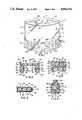
- FIG. 6 is a block diagram of the apparatus for carrying out the method of the present invention for making a stand-up plastic bag, and also a front elevational view of the bag of the first embodiment as produced by the method.
- FIG. 6A is a front elevational view of a section of the film web representing one bag blank moving through the appartus of FIG. 6, illustrating the condition of the bag blank after the film folding, gusset forming and closure locking operations have been completed by the apparatus.
- FIG. 6B is another front elevational view of the same bag blank moving through the apparatus of FIG. 6, illustrating the condition of the bag blank after the gusset sealing operation has been completed.
- FIG. 6C is yet another front elevational view of the same bag blank moving through the apparatus of FIG. 6, illustrating the condition of the bag blank after the side seam double-sealing operations have been completed.
- FIG. 7 is a side plan view of a second embodiment of a stand-up plastic bag constructed in accordance with the principles of the present invention.
- FIG. 8 is a perspective view of the bag of the second embodiment.
- FIGS. 1-5 of the drawings illustrate a stand-up plastic bag, generally designated 10 and comprising one embodiment of the present invention.
- the bag 10 includes a pair of front and rear side walls 12, 14 and a pair of front and rear bottom gusset walls 16, 18 (see FIGS. 2-5).
- the side walls 12, 14 define an open mouth 20 for the bag 10 between upper edges 12A, 14A of the walls 12, 14.
- the front and rear bottom gusset walls 16, 18 are disposed between the side walls 12, 14 and each have respective upper and lower portions 22, 24 and 26, 28.
- the upper portions 22, 26 of the gusset walls 16, 18 are integrally connected and foldable relative to one another about a center fold line 30.
- the upper portions 22, 26 of the gusset walls 16, 18 are integrally connected and foldable relative to the respective lower portions 24, 28 thereof about front and rear fold lines 32A, 32b. Also, the lower portions 24, 28 of the gusset walls 16, 18 at their lower edges 16A, 18A are integrally connected and folded relative to the lower edges 12B, 14B of the side walls 12, 14.
- FIG. 2 there is illustrated a cross-section taken through lower portions 34, 36 of the front and rear side walls 12, 14 corresponding to the lower portions 24, 28 of the front and rear bottom gusset walls 16, 18.
- the composition of the film of which each of the walls 12-18 is formed is depicted most clearly in FIG. 2 wherein it is illustrated that the film is multi-layered, being composed of two different heat-sealable thermoplastic materials 38 and 40 and an adhesive or glue material 42 there between bonding the two thermoplastic materials together. It is important that the thermoplastic materials selected be heat-sealable at different ranges of temperatures.
- the material 38 which ultimately will be on the interior surfaces of the walls 12-18 must be heat-sealable within a temperature range which is lower than the temperature range at which the material 40 on the exterior surfaces of the walls 12-18 will be heat sealable.
- Maintenance of this difference in heat sealing temperature ranges between the exterior and interior surfaces of the walls 12-18 is important in order to avoid heat sealing together the facing exterior surfaces 44, 46 of the front and rear bottom gusset walls 16, 18, shown in FIG. 2, at the same time that the interior surfaces 48, 50 of their lower portions 24, 28 which face interior surfaces 52, 54 of the lower portions 34, 36 of the front and rear side walls 12, 14 are heat sealed thereto to form a support band 56 of a stand-up base 58 for the bag 10, as will be described in detail below.
- the preferred composition of the film is a multi-layer coextrusion of Nylon (polyamide)/glue/PE (polyethylene) in thicknesses of about 0.1-1.0 mils, 0.1-0.5 mils and 0.5-5.0 mils respectively. Bag stability has been found to increase with film modulus (stiffness).
- the heat sealing temperature range of the polyethylene material 38 is from about 125° to 190° C.
- the preferred temperature for heat sealing the material 38 on the interior surfaces of the walls 12-18 is approximately 130° to 150° C.
- the heat sealing temperature range of the Nylon material 40 is from about 190° to 280° C.
- the preferred temperature range for heat sealing the material 40 on the exterior surfaces of the walls 12-18 is approximately 210° to 250° C.
- thermoplastics like polycarbonate, polyester, polyvinylidene chloride, poly-4-methyl-1-pentene, polyphenylene sulfide and other higher temperature sealing thermoplastics may be substituted for the Nylon and other polyolefins, polyvinylchloride, ethylene vinyl acetate, polystyrene, polyisoprene, and other lower temperature sealing thermoplastics may be substituted for the polyethylene.
- the preferred composition of the film is particularly well suited for a stand-up bag to hold hot liquids--i.e. it may be used for boiling water temperature liquids in either microwave or in boiling water heating.
- the Nylon layer has high modulus and high heat distortion features which add to hot liquid stand up stability and boiling water performance.
- the preferred composition of the film is also particularly well suited for freezer use.
- the relatively thick polyethylene layer provides toughness and flexibility even at freezer temperatures.
- the upper portions 22, 26 of the front and rear bottom gusset walls 16, 18 are interconnected together to define a bottom wall 60 which extends between the front and rear side walls 12, 14 and which, because of the other feature of the bag of the present invention, will present a relatively flat support base when the bag is in use.
- the lower portions 24, 28 of the front and rear bottom gusset walls 16, 18 are joined by heat seals 62, 64 to lower portions 34, 36 of the front and rear side walls 12, 14 at contiguous portions of the thermoplastic material 38 on their respective interior surfaces 48-54.
- the gusset and side wall lower portions 24, 28 and 34, 36 cooperate to form the upright support band 56 which is connected to and extends below the periphery of the bottom wall 60.
- the configuration of the bottom wall 60 preferably either is concave-shaped, as shown in the first embodiment of FIG. 1, or has a shape wherein the opposite end portions of the bottom wall are oppositely inclined at about forty-five degrees and then interconnected by a generally flat or planar intermediate portion, as shown in the second (and preferred) embodiment of FIGS. 7-8, discussed in more detail below.
- several limited regions 65 between the respective interior surfaces 48-54 of the gusset and side wall lower portions 24, 28, 34, 36, as outlined in FIGS. 1, 6B, 7 and 8 are left unsealed to minimize the amount of distortion of the material in the band 56 which ordinarily results from the heat sealing process. Regions 65 also provide a "cool corner" for the user to hold onto when emptying hot contents from the bag.
- the formation of the band 56 (see FIG. 1) of the stand-up base 58 is completed by joining together the opposite right longitudinal edges 66, 68 and left longitudinal edges of the front and rear bottom gusset walls 16, 18 of FIG. 1 by the formation of respective heat seals 70. Only the right longitudinal edges 66, 68 of the gusset walls 16, 18 and the right heat seal 70 are shown in detail in FIG. 5.
- the heat seals 70 are formed at contiguous portions of the thermoplastic material 40 on the facing exterior surfaces 44, 46 (See FIG. 2) thereof at the longitudinal edges 66, 68 adjacent the gussetted portion of the bag 10.
- the upright support band 56 now consitutes a continuous self-standing structure which along with the bottom wall 60 provides a sturdy and stable stand-up base 58 for the bag 10 which renders the bag capable of standing up by itself before, during and after being filled.
- the interaction of support band 56 with the film stiffness and other structural features permits the bag to stand up when empty or even when filled with boiling water.
- the opposite right longitudinal edges 72 and left longitudinal edges 74 of the front and rear side walls 12, 14 are joined with the aforementioned right longitudinal edges 66, 68 and left longitudinal edges of the gusset walls 16, 18 by heat seals 76 formed at contiguous portions of the thermoplastic material 38 on interior surfaces thereof, as shown both in FIGS. 3 and 4.
- These heat seals 76 provide a reliable, leak-proof seal along the opposite longitudinal edges adjacent the non-gussetted portion of the bag 10.
- an additional end seal 78 can be provided between the thermoplastic material 40 on the exterior surfaces of the longitudinal edges 72, 74 of the side walls 12, 14 if the bags 10 are severed from one another by using a hot wire or hot knife severing technique.
- this additional seal is not essential.
- a guillotine knife cut at the center of the bar seal is preferred for the sake of process simplicity.
- the bag 10 also may preferably include an openable and closable closure device 80 of any suitable conventional design although a zipper-type closure device is preferred.
- the device 80 is defined on the front and rear side walls 12, 14 just below and adjacent to the bag mouth 20 defined at the upper edges 12A, 14A, thereof.
- the components 80A, 80B of the closure device 80 can be integrally formed on the film 82 or laminated thereon.
- a bag with an approximate 6 cup capacity (6.2 cups) would have a preferred height of approximately 7.0 inches, a preferred width of aprroximately 9.5 inches, and a preferred gusset height of approximately 2.0 inches.
- a smaller bag such as one having a 3.4 cup capacity, it would preferrably have a height of 5.5 inches, a width of 8.0 inches, and a gusset height of 2.0 inches.
- FIGS. 6 and 6A-6C the steps involved in the method of the present invention for making the stand-up reclosable plastic bag 10 are shown in block form and the states of a bag at the various stages in its formation are illustrated.
- the process may be a continuous, a semi-continous or a multi-step batch process.
- the components used in the method are individually well-known in the art and to illustrate them in detail herein would not make it easier to understand the method of the present invention.
- the components used in the method herein are generally the same as components schematically illustrated in the afore-cited U.S. patents to Doyen et al and Kan. The differences reside not in the components per se but the steps they are employed to carry out in the method of the present invention.
- Film web roll 84 represents the supplying of a web of the multi-layered film 82 from a roll thereof.
- a web of multi-layered film 82 may be supplied directly, as fabricated, from an extrusion and/or laminating line.
- the film 82 has the two different thermoplastic materials 38, 40 (FIG. 2), for instance polyethylene and Nylon, which are heat-sealable upon applying of heat at temperatures within different ranges, as described previously.
- Film folding, gusset forming and closure locking station 86 represents performance of the steps of folding the film 82 to form the front and rear side walls 12, 14 and to form the front and rear bottom gusset walls 16, 18 (FIGS. 1 and 2) being disposed and folded inwardly between the side walls so that the Nylon and polyethylene materials are respective on the interior and exterior surfaces of the side and gusset walls, as was described previously. Also, station 86 represents the locking or closing of the components 80A, 80B of the closure device 80. The state or condition of a partially completed bag after leaving block 86 would resemble that depicted in FIG. 6A. All heat sealing steps can be interchanged, reversed in order or combined into a single sealing step containing differential temperature zones.
- block 88 represents the applying of heat, by use of shoe or bar-like members, to the lower portions 24, 28 of the gusset walls and lower portions 34, 36 of the side walls 12, 14 (FIG. 2).
- the application of heat within the lower one of the two aforementioned temperature ranges causes joining of the lower portions at their interior surfaces, but not at their exterior surfaces, by forming the above-described heat seals 62, 64 in FIG. 2 and as represented by the dotted regions in FIG. 6B. That figure shows the condition of the partially completed bag after leaving block 88. Partial formation of the support band 56 has now taken place.
- Block 90 represents forming heat seals 76 (FIG. 4 and 5) as depicted by the dotted regions in FIG. 6C, to join the front and rear side walls 12, 14 with the front and rear bottom gusset walls 16, 18 along the opposite longitudinal edges thereof at contiguous portions of the polyethylene material 38 on their interior surfaces.
- Heat seals 76 are formed by applying heat at the lower temperature range as before using conventional sealing bars.
- Block 92 represents forming heat seals 70 (FIG. 5) to join the front and rear bottom gusset walls together along their opposite longitudinal edges at contiguous portions of the Nylon material 40 on the exterior surfaces thereof and thereby complete formation of the upright support band 56, as described above.
- heat seals 70 heat is now applied to the gusset wall edges at a temperature within the higher temperature range using conventional sealing bars.
- Block 92 can also represent a combined or separate step of separating the film 82 through into completed plastic bags by severing the film through at each of the heat seals at each of the longitudinal edges of the walls. If the sealing and severing are combined, then a conventional hot wire or hot knife is used. However, if they are performed successively, then a tab sealing bar is used to seal the gusset edges followed by an unheated conventional severing knife.
- FIGS. 7-8 there is shown a second and preferred embodiment of bag 10.
- the preferred stand-up, reclosable bag shown in FIGS. 7-8 is made by the same procedure shown in FIG. 6 and utilizes the same materials and structural elements described with reference to FIGS. 1-5 and, therefore like reference numerals have been used.
- the bag of FIGS. 7-8 has a bottom wall with end portions oppositely inclined at about forty-five degrees. This is best seen in FIG. 8 where center fold line 30 is horizontal in the middle portion thereof, but has an approximate 45° incline at the ends 30A and 30B, thereof.
- That approximate 45 degree incline is essentially the same as straight 45 degree heat seal of support band 56 at the opposite ends 56A and 56B thereof, as best seen in FIG. 7.
- the use of approximate 45° angles at ends 30A and 30B of center fold line 30 and at ends 56A and 56B of support band 56 results in flat bottom with an essentially rectangular base.
- That design has been found to be the most stable. In particular it optimizes hot liquid stability with the bag either open or closed. This is because the bag design of FIGS. 7-8 has a lower center of gravity which is especially important with hot liquids. A hot liquid softens the bag film and the softened bag tends to "sag" more than an unheated bag. The lower center of gravity better accommodates the "sag” and prevents the bag from tipping over under those conditions.
- a bag with an approximate 6 cup capacity would have a preferred height of approximately 6.0 inches, a preferred width of approximately 10.0 inches and a preferred gusset height of approximately 2.0 inches.
- a smaller gusset height of approximately 1.5 inches may be used; although, a 2.0 inch gusset length is still preferred for process simplicity.
- a bag with a 2.9 cup capacity having 5 inch height, an 8 inch width, and a gussett height of 2.0 inches was found to be particularly stable.
Abstract
A stand-up plastic bag has a pair of front and rear side walls defining an open bag mouth at upper edges thereof, and a pair of front and rear bottom gusset walls being disposed between the side walls. The walls are composed of a multi-layered film of different, heat-sealable, coextruded thermoplastics, such as polyethylene and Nylon. Polyethylene is on the interior surfaces and Nylon is on the exterior surfaces of the walls. The gusset walls have upper portions interconnected together to form a bottom wall extending between the front and rear side walls. The gusset walls also have lower portions joined by heat seals to lower portion of the front and rear side walls at contiguous portions of polyethylene material on their interior surfaces to form a support band which connects to and extends below the bottom wall. The front and rear gusset walls also have opposite longitudinal edges joined together by heat seals at contiguous portions of Nylon material on the exterior surfaces thereof which complete formation of the support band as a continuous self-standing structure that defines with the bottom wall a stand-up base on the bag.
Description
This is a continuation of application Ser. No. 171,053 filed Mar. 21, 1988 now U.S. Pat. No. 4,837,849.
The present invention generally relates to plastic bags and, more particularly, to a plastic bag capable of standing up by itself before, during and after being filled and to a method making the bag.
So-called stand-up, free-standing or self-standing plastic bags are well-known in the prior art. Representative of the prior art are the plastic bags disclosed in U.S. Pat. Nos. to Knuetter (2,265,075), Doyen et al (3,380,646), Kugler (3,437,258), Michel (3,715,074) and Bustin (4,353,497). Also, well-known in the prior art are plastic bags incorporating a zipper-type closure device along the top opening or mouth of the bags. Representative of the prior art are the plastic bags disclosed in a U.S. Pat. No. to Ausnit (4,601,694) and a U.K. Patent Application to Kirkpatrick (2,047,199). Further, U.S. Pat. Nos. to Kan (3,980,225 and 4,055,109) disclose a self-standing plastic bag which also incorporates a zipper-type closure device along its mouth.
Market research has shown that consumers greatly desire a stand-up, reclosable plastic bag because of the convenience of filling and storing highly liquid foods and of microwave heating of foods directly in the bag. Some known stand-up bags attempt to provide the stand-up capability merely by use of a simple bottom gusset alone or supplemented with seals added in the gusset structure. A simple bottom gusset sealed at its sides does not provide a normal consumer plastic bag with a sufficient stand-up feature. Such plastic bag typically made from polyethylene film, for example of under 1.0 mil thickness, is too limp to stand up from the gusseted bottom.
Other plastic films of greater thickness and higher modulus can be fabricated into a bag that will stand up from a simple bottom gusset. One plastic bag currently available uses a very deep bottom gusset design to provide certain advantages in food storage and microwave heating, but some difficulty has been experienced in filling and emptying this bag. The bag does not stand up easily when empty, and the zipper-type closure is difficult to maintain open when filling and emptying this bag. Other currently-available stand-up bags seal the bottom gusset into a stand-up base that is much more stable than the simple bottom gusset. The self-standing bag of the above-cited U.S. patents to Kan is an example of a bag having such stand-up base.
It is perceived that additional improvements need to be made before consumers will be provided with a stand-up reclosable plastic bag that fully meets their needs. These improvements must relate to the provision of a bag with a stronger, sturdier and more stable stand-up base, one which will faithfully support the bag when empty as well as during and after filling, and a bag with a more reliable, leak-proof side seam. Aslo, the improvements must allow a simpler and less costly method of making the bag.
The present invention provides a stand-up plastic bag and method of making same designed to satisfy the aforementioned needs.
The stand-up plastic bag of the present invention comprises a pair of front and rear side walls which define an open mouth at upper edges of the side walls, and a pair of front and rear bottom gusset walls disposed between the side walls. The front and rear side walls and the front and rear bottom gusset walls are composed of a multi-layered film of first and second heat-sealable thermoplastic materials. The first material is on interior surfaces of the walls and heat-sealable at a temperature within a first temperature range. The second material is on exterior surfaces of walls and heat-sealable at a temperature within a second temperature range greater than the first temperature range.
The bottom gusset walls have upper portions that are interconnected together to define a bottom wall extending between the front and rear side walls. The bottom gusset walls also have lower portions joined by heat seals to lower portions of the front and rear side walls at contiguous portions of the first material on the interior surfaces thereof to form a support band connected to and extending below the periphery of the bottom wall. The bottom gusset walls further have opposite longitudinal edges joined together by heat seals at contiguous portions of the second material on the exterior surfaces thereof which complete formation of the support band as a continuous self-standing structure and define with the bottom wall a stand-up base on the bag.
Further, the front and rear side walls and the front and rear bottom gusset walls along opposite longitudinal edges of the walls are joined together by heat seals at contiguous portions of the first material on interior surfaces thereof. Also, an openable and closable closure device is defined on the front and rear side walls below and adjacent to the bag mouth defined at the upper edges of the side walls.
The method of the present invention for making the stand-up plastic bag comprises the steps of: supplying a multi-layered film of the first and second heat-sealable thermoplastic materials; folding the film to form the front and rear side walls and the front and rear bottom gusset walls disposed between the side walls with interior surfaces of the walls having the first material thereon and exterior surfaces of the walls having the second material thereon; forming heat seals which join lower portions of the front and rear bottom gusset walls with corresponding lower portions of the front and rear side walls at contiguous regions of the first material on the interior surfaces thereof and thereby form a support band being connected to and extending below the periphery of a bottom wall formed by connected upper portions of the front and rear bottom gusset walls which extend between the front and rear side walls; forming heat seals which join the front and rear side walls with the front and rear bottom gusset walls along opposite longitudinal edges thereof at contiguous portions of the first material on interior surface of the longitudinal edges of the walls; forming heat seals which join the front and rear bottom gusset walls together along their opposite longitudinal edges at contiguous portions of the second material on the exterior surfaces thereof and thereby complete formation of the support band as a continuous self-standing structure to define with the bottom wall a stand-up base on a bag; and separating the film into completed plastic bags by severing the film through at each of the heat seals at each of the longitudinal edges of the walls.
Accordingly, it is an object of the present invention to provide a stand-up plastic bag that has a stronger, sturdier and more stable stand-up base capable of supporting the bag whether empty or full; to provide a stand-up plastic bag that has more reliable, leak-proof side seams; and to provide a stand-up plastic bag that is simplier and less costly to make because of its employment of heat seals between materials on the interior surfaces and a heat seal between materials on the exterior surfaces of the longitudinal ends of the gusset walls which eliminate the necessity of punching holes or cutouts through the gusset walls, as done in prior art bags, in order to seal the opposite side walls of the bag together in the region of the gusset wall longitudinal ends; and to provide a method of making such a stand-up plastic bag. Other objects and advantages of the invention will be apparent from the following description, the accompanying drawings and the appended claims.
FIG. 1 is a perspective view of a first embodiment of a stand-up plastic bag constructed in accordance with the principles of the present invention.
FIG. 2 is an enlarged cross-sectional view of the bag taken along line 2--2 of FIG. 1.
FIG. 3 is another enlarged cross-sectional view of the bag taken along line 3--3 of FIG. 1.
FIG. 4 is yet another enlarged cross-sectional view of the bag taken along line 4--4 of FIG. 1.
FIG. 5 is still another enlarged cross-sectional view of the bag taken along line 5--5 of FIG. 1.
FIG. 6 is a block diagram of the apparatus for carrying out the method of the present invention for making a stand-up plastic bag, and also a front elevational view of the bag of the first embodiment as produced by the method.
FIG. 6A is a front elevational view of a section of the film web representing one bag blank moving through the appartus of FIG. 6, illustrating the condition of the bag blank after the film folding, gusset forming and closure locking operations have been completed by the apparatus.
FIG. 6B is another front elevational view of the same bag blank moving through the apparatus of FIG. 6, illustrating the condition of the bag blank after the gusset sealing operation has been completed.
FIG. 6C is yet another front elevational view of the same bag blank moving through the apparatus of FIG. 6, illustrating the condition of the bag blank after the side seam double-sealing operations have been completed.
FIG. 7 is a side plan view of a second embodiment of a stand-up plastic bag constructed in accordance with the principles of the present invention.
FIG. 8 is a perspective view of the bag of the second embodiment.
Reference is made to FIGS. 1-5 of the drawings which illustrate a stand-up plastic bag, generally designated 10 and comprising one embodiment of the present invention. In its basic components, the bag 10 includes a pair of front and rear side walls 12, 14 and a pair of front and rear bottom gusset walls 16, 18 (see FIGS. 2-5). The side walls 12, 14 define an open mouth 20 for the bag 10 between upper edges 12A, 14A of the walls 12, 14. The front and rear bottom gusset walls 16, 18 are disposed between the side walls 12, 14 and each have respective upper and lower portions 22, 24 and 26, 28. The upper portions 22, 26 of the gusset walls 16, 18 are integrally connected and foldable relative to one another about a center fold line 30. The upper portions 22, 26 of the gusset walls 16, 18 are integrally connected and foldable relative to the respective lower portions 24, 28 thereof about front and rear fold lines 32A, 32b. Also, the lower portions 24, 28 of the gusset walls 16, 18 at their lower edges 16A, 18A are integrally connected and folded relative to the lower edges 12B, 14B of the side walls 12, 14.
Referring specifically to FIG. 2, there is illustrated a cross-section taken through lower portions 34, 36 of the front and rear side walls 12, 14 corresponding to the lower portions 24, 28 of the front and rear bottom gusset walls 16, 18. The composition of the film of which each of the walls 12-18 is formed is depicted most clearly in FIG. 2 wherein it is illustrated that the film is multi-layered, being composed of two different heat- sealable thermoplastic materials 38 and 40 and an adhesive or glue material 42 there between bonding the two thermoplastic materials together. It is important that the thermoplastic materials selected be heat-sealable at different ranges of temperatures. Particularly, the material 38 which ultimately will be on the interior surfaces of the walls 12-18 must be heat-sealable within a temperature range which is lower than the temperature range at which the material 40 on the exterior surfaces of the walls 12-18 will be heat sealable. Maintenance of this difference in heat sealing temperature ranges between the exterior and interior surfaces of the walls 12-18 is important in order to avoid heat sealing together the facing exterior surfaces 44, 46 of the front and rear bottom gusset walls 16, 18, shown in FIG. 2, at the same time that the interior surfaces 48, 50 of their lower portions 24, 28 which face interior surfaces 52, 54 of the lower portions 34, 36 of the front and rear side walls 12, 14 are heat sealed thereto to form a support band 56 of a stand-up base 58 for the bag 10, as will be described in detail below.
By way of example, the preferred composition of the film is a multi-layer coextrusion of Nylon (polyamide)/glue/PE (polyethylene) in thicknesses of about 0.1-1.0 mils, 0.1-0.5 mils and 0.5-5.0 mils respectively. Bag stability has been found to increase with film modulus (stiffness). The heat sealing temperature range of the polyethylene material 38 is from about 125° to 190° C. The preferred temperature for heat sealing the material 38 on the interior surfaces of the walls 12-18 is approximately 130° to 150° C. The heat sealing temperature range of the Nylon material 40 is from about 190° to 280° C. The preferred temperature range for heat sealing the material 40 on the exterior surfaces of the walls 12-18 is approximately 210° to 250° C. Other materials, thicknesses and heat sealing temperature ranges are possible. For example, thermoplastics like polycarbonate, polyester, polyvinylidene chloride, poly-4-methyl-1-pentene, polyphenylene sulfide and other higher temperature sealing thermoplastics may be substituted for the Nylon and other polyolefins, polyvinylchloride, ethylene vinyl acetate, polystyrene, polyisoprene, and other lower temperature sealing thermoplastics may be substituted for the polyethylene.
The preferred composition of the film is particularly well suited for a stand-up bag to hold hot liquids--i.e. it may be used for boiling water temperature liquids in either microwave or in boiling water heating. The Nylon layer has high modulus and high heat distortion features which add to hot liquid stand up stability and boiling water performance.
The preferred composition of the film is also particularly well suited for freezer use. The relatively thick polyethylene layer provides toughness and flexibility even at freezer temperatures.
Referring still to FIG. 2 as well as FIG. 1, it will be seen that the upper portions 22, 26 of the front and rear bottom gusset walls 16, 18 are interconnected together to define a bottom wall 60 which extends between the front and rear side walls 12, 14 and which, because of the other feature of the bag of the present invention, will present a relatively flat support base when the bag is in use. Thus, the lower portions 24, 28 of the front and rear bottom gusset walls 16, 18 are joined by heat seals 62, 64 to lower portions 34, 36 of the front and rear side walls 12, 14 at contiguous portions of the thermoplastic material 38 on their respective interior surfaces 48-54. By such heat seals 62, 64, the gusset and side wall lower portions 24, 28 and 34, 36 cooperate to form the upright support band 56 which is connected to and extends below the periphery of the bottom wall 60. The configuration of the bottom wall 60 preferably either is concave-shaped, as shown in the first embodiment of FIG. 1, or has a shape wherein the opposite end portions of the bottom wall are oppositely inclined at about forty-five degrees and then interconnected by a generally flat or planar intermediate portion, as shown in the second (and preferred) embodiment of FIGS. 7-8, discussed in more detail below. Also, preferably, several limited regions 65 between the respective interior surfaces 48-54 of the gusset and side wall lower portions 24, 28, 34, 36, as outlined in FIGS. 1, 6B, 7 and 8 are left unsealed to minimize the amount of distortion of the material in the band 56 which ordinarily results from the heat sealing process. Regions 65 also provide a "cool corner" for the user to hold onto when emptying hot contents from the bag.
As shown in FIGS. 4 and 5, the formation of the band 56 (see FIG. 1) of the stand-up base 58 is completed by joining together the opposite right longitudinal edges 66, 68 and left longitudinal edges of the front and rear bottom gusset walls 16, 18 of FIG. 1 by the formation of respective heat seals 70. Only the right longitudinal edges 66, 68 of the gusset walls 16, 18 and the right heat seal 70 are shown in detail in FIG. 5. The heat seals 70 are formed at contiguous portions of the thermoplastic material 40 on the facing exterior surfaces 44, 46 (See FIG. 2) thereof at the longitudinal edges 66, 68 adjacent the gussetted portion of the bag 10. The upright support band 56 now consitutes a continuous self-standing structure which along with the bottom wall 60 provides a sturdy and stable stand-up base 58 for the bag 10 which renders the bag capable of standing up by itself before, during and after being filled. The interaction of support band 56 with the film stiffness and other structural features permits the bag to stand up when empty or even when filled with boiling water.
Additionally, the opposite right longitudinal edges 72 and left longitudinal edges 74 of the front and rear side walls 12, 14 are joined with the aforementioned right longitudinal edges 66, 68 and left longitudinal edges of the gusset walls 16, 18 by heat seals 76 formed at contiguous portions of the thermoplastic material 38 on interior surfaces thereof, as shown both in FIGS. 3 and 4. These heat seals 76 provide a reliable, leak-proof seal along the opposite longitudinal edges adjacent the non-gussetted portion of the bag 10. As seen in FIG. 3, an additional end seal 78 can be provided between the thermoplastic material 40 on the exterior surfaces of the longitudinal edges 72, 74 of the side walls 12, 14 if the bags 10 are severed from one another by using a hot wire or hot knife severing technique. However, this additional seal is not essential. A guillotine knife cut at the center of the bar seal is preferred for the sake of process simplicity.
As seen in FIG. 1, the bag 10 also may preferably include an openable and closable closure device 80 of any suitable conventional design although a zipper-type closure device is preferred. The device 80 is defined on the front and rear side walls 12, 14 just below and adjacent to the bag mouth 20 defined at the upper edges 12A, 14A, thereof. The components 80A, 80B of the closure device 80, as seen schematically in FIG. 6, can be integrally formed on the film 82 or laminated thereon.
In the bag of the first embodiment shown in FIGS. 1-5, a bag with an approximate 6 cup capacity (6.2 cups) would have a preferred height of approximately 7.0 inches, a preferred width of aprroximately 9.5 inches, and a preferred gusset height of approximately 2.0 inches. For a smaller bag, such as one having a 3.4 cup capacity, it would preferrably have a height of 5.5 inches, a width of 8.0 inches, and a gusset height of 2.0 inches.
Turning now to FIGS. 6 and 6A-6C, the steps involved in the method of the present invention for making the stand-up reclosable plastic bag 10 are shown in block form and the states of a bag at the various stages in its formation are illustrated. The process may be a continuous, a semi-continous or a multi-step batch process. The components used in the method are individually well-known in the art and to illustrate them in detail herein would not make it easier to understand the method of the present invention. The components used in the method herein are generally the same as components schematically illustrated in the afore-cited U.S. patents to Doyen et al and Kan. The differences reside not in the components per se but the steps they are employed to carry out in the method of the present invention.
Film folding, gusset forming and closure locking station 86 represents performance of the steps of folding the film 82 to form the front and rear side walls 12, 14 and to form the front and rear bottom gusset walls 16, 18 (FIGS. 1 and 2) being disposed and folded inwardly between the side walls so that the Nylon and polyethylene materials are respective on the interior and exterior surfaces of the side and gusset walls, as was described previously. Also, station 86 represents the locking or closing of the components 80A, 80B of the closure device 80. The state or condition of a partially completed bag after leaving block 86 would resemble that depicted in FIG. 6A. All heat sealing steps can be interchanged, reversed in order or combined into a single sealing step containing differential temperature zones.
Next, block 88 represents the applying of heat, by use of shoe or bar-like members, to the lower portions 24, 28 of the gusset walls and lower portions 34, 36 of the side walls 12, 14 (FIG. 2). The application of heat within the lower one of the two aforementioned temperature ranges causes joining of the lower portions at their interior surfaces, but not at their exterior surfaces, by forming the above-described heat seals 62, 64 in FIG. 2 and as represented by the dotted regions in FIG. 6B. That figure shows the condition of the partially completed bag after leaving block 88. Partial formation of the support band 56 has now taken place.
The next successive blocks 90 and 92 can be arranged as shown or reversed. Block 90 represents forming heat seals 76 (FIG. 4 and 5) as depicted by the dotted regions in FIG. 6C, to join the front and rear side walls 12, 14 with the front and rear bottom gusset walls 16, 18 along the opposite longitudinal edges thereof at contiguous portions of the polyethylene material 38 on their interior surfaces. Heat seals 76 are formed by applying heat at the lower temperature range as before using conventional sealing bars.
Referring now to FIGS. 7-8, there is shown a second and preferred embodiment of bag 10. The preferred stand-up, reclosable bag shown in FIGS. 7-8 is made by the same procedure shown in FIG. 6 and utilizes the same materials and structural elements described with reference to FIGS. 1-5 and, therefore like reference numerals have been used.
However, unlike the bag illustrated in the first embodiment of FIGS. 1-5 wherein a concave-shaped bottom wall 60 is used, the bag of FIGS. 7-8 has a bottom wall with end portions oppositely inclined at about forty-five degrees. This is best seen in FIG. 8 where center fold line 30 is horizontal in the middle portion thereof, but has an approximate 45° incline at the ends 30A and 30B, thereof.
That approximate 45 degree incline is essentially the same as straight 45 degree heat seal of support band 56 at the opposite ends 56A and 56B thereof, as best seen in FIG. 7. The use of approximate 45° angles at ends 30A and 30B of center fold line 30 and at ends 56A and 56B of support band 56 results in flat bottom with an essentially rectangular base. That design has been found to be the most stable. In particular it optimizes hot liquid stability with the bag either open or closed. This is because the bag design of FIGS. 7-8 has a lower center of gravity which is especially important with hot liquids. A hot liquid softens the bag film and the softened bag tends to "sag" more than an unheated bag. The lower center of gravity better accommodates the "sag" and prevents the bag from tipping over under those conditions.
In the preferred bag design, of the second embodiment shown in FIGS. 7-8 a bag with an approximate 6 cup capacity (6.1 cups) would have a preferred height of approximately 6.0 inches, a preferred width of approximately 10.0 inches and a preferred gusset height of approximately 2.0 inches. For a smaller bag, such as having an approximate 2 cup capacity, a smaller gusset height of approximately 1.5 inches may be used; although, a 2.0 inch gusset length is still preferred for process simplicity. For example, a bag with a 2.9 cup capacity having 5 inch height, an 8 inch width, and a gussett height of 2.0 inches was found to be particularly stable.
Having thus described the stand-up plastic bag and method of making same of the present invention in detail and by reference to a preferred embodiment thereof, it will be apparent that certain modifications and variations are possible without departing from the scope of the invention defined in the appended claims.
Claims (8)
1. A method of making a stand-up plastic bag, comprising the steps of:
(a) supplying a multi-layered film of first and second thermoplastic materials, said first material being heat-sealable at a temperature within a first temperature range and said second material being heat-sealable at a temperature within a second temperature range which is a range of temperatures higher than the temperatures in said first temperature range;
(b) folding said film to form a pair of front and rear side walls and a pair of front and rear bottom gusset walls disposed between said side walls with said first and second materials being on respective interior and exterior surfaces of said side and gusset walls;
(c) heat sealing at a temperature within said first temperature range to form a first set of heat seals which join lower portions of said front and rear bottom gusset walls with corresponding lower portions of said front and rear side walls at contiguous regions of said first material on said interior surfaces thereof and to form a bottom wall of connected upper portions of said front and rear bottom gusset walls which extend between said front and rear side walls, said first set of heat seals forming a support band which is connected to and extends below the periphery of said bottom wall;
(d) heat sealing at a temperature within said first temperature range to form a second set of heat seals which join said front and rear side walls with said front and rear bottom gusset walls along opposite longitudinal edges thereof at contiguous portions of said first material on interior surfaces of said longitudinal edges of said walls;
(e) heat sealing at a temperature within said second temperature range to form a third set of heat seals which join said front and rear bottom gusset walls together along their opposite longitudinal edges at contiguous portions of said second material on said exterior surfaces thereof and thereby complete formation of said support band as a continuous self-standing structure to define with said bottom wall a stand-up base on a bag; and
(f) separating said film into completed plastic bags by severing said film through at each of said heat seals at each of said longitudinal edges of said walls.
2. The method of claim 1 in which said first temperature range is from about 125° to 190° C.
3. The method of claim 2 in which said temperature within said first temperature range is preferably approximately 130° to 150° C.
4. The method of claim 1 in which said second temperature range is from about 190° to 280° C.
5. The method of claim 4 in which said temperature within said second temperature range is preferably approximately 210° to 250° C.
6. The method of claim 1 in which said film is a web of coextruded layers of said first and second thermoplastic materials.
7. The method of claim 1 in which said film contains components of a closure device thereon.
8. The method of claim 1 in which said support band has a straight forty-five degree heat seal at the opposite ends thereof.
Priority Applications (3)
| Application Number | Priority Date | Filing Date | Title |
|---|---|---|---|
| US07/303,310 US4954124A (en) | 1988-03-21 | 1989-01-30 | Stand-up plastic bag and method of making same |
| US07/533,620 US4997416A (en) | 1988-03-21 | 1990-06-05 | Method of making a stand-up plastic bag |
| US07/533,621 US5080643A (en) | 1988-03-21 | 1990-06-05 | Method of making a stand-up plastic bag |
Applications Claiming Priority (2)
| Application Number | Priority Date | Filing Date | Title |
|---|---|---|---|
| US07/171,053 US4837849A (en) | 1988-03-21 | 1988-03-21 | Stand-up plastic bag and method of making same |
| US07/303,310 US4954124A (en) | 1988-03-21 | 1989-01-30 | Stand-up plastic bag and method of making same |
Related Parent Applications (2)
| Application Number | Title | Priority Date | Filing Date |
|---|---|---|---|
| US07/171,053 Continuation US4837849A (en) | 1988-03-21 | 1988-03-21 | Stand-up plastic bag and method of making same |
| US07/171,063 Division US4882201A (en) | 1988-03-21 | 1988-03-21 | Non-toxic aryl onium salts, UV curable coating compositions and food packaging use |
Related Child Applications (2)
| Application Number | Title | Priority Date | Filing Date |
|---|---|---|---|
| US07/533,621 Continuation-In-Part US5080643A (en) | 1988-03-21 | 1990-06-05 | Method of making a stand-up plastic bag |
| US07/533,620 Continuation-In-Part US4997416A (en) | 1988-03-21 | 1990-06-05 | Method of making a stand-up plastic bag |
Publications (1)
| Publication Number | Publication Date |
|---|---|
| US4954124A true US4954124A (en) | 1990-09-04 |
Family
ID=26866692
Family Applications (1)
| Application Number | Title | Priority Date | Filing Date |
|---|---|---|---|
| US07/303,310 Expired - Fee Related US4954124A (en) | 1988-03-21 | 1989-01-30 | Stand-up plastic bag and method of making same |
Country Status (1)
| Country | Link |
|---|---|
| US (1) | US4954124A (en) |
Cited By (35)
| Publication number | Priority date | Publication date | Assignee | Title |
|---|---|---|---|---|
| US5080643A (en) * | 1988-03-21 | 1992-01-14 | Dow Brands Inc. | Method of making a stand-up plastic bag |
| US5174658A (en) * | 1991-07-12 | 1992-12-29 | The Procter & Gamble Company | Self-expanding and reclosable flexible pouch |
| US5184896A (en) * | 1991-10-11 | 1993-02-09 | The Procter & Gamble Company | Self-expanding flexible pouch including improved extensible stay to maximize opening |
| US5593529A (en) * | 1990-01-18 | 1997-01-14 | Pall Corporation | Cylindrical filters and their manufacture |
| AU681888B2 (en) * | 1993-08-06 | 1997-09-11 | Gromark Packaging Pty Ltd | Coextruded plastics packaging for bales |
| US5830118A (en) * | 1995-09-15 | 1998-11-03 | Klockner Bartelt, Inc. | Packaging machine for forming free-standing pouches |
| US6303363B1 (en) | 1997-05-02 | 2001-10-16 | International Bioproducts, Inc. | Method for culturing microorganisms in prefilled flexible containers |
| US20030031387A1 (en) * | 2001-08-08 | 2003-02-13 | Gipson Kyle G. | Packaging material and containers formed therefrom |
| US20040025476A1 (en) * | 2002-04-10 | 2004-02-12 | Oliverio Frank G. | Stand-up pouch forming, filling and sealing |
| US20040092375A1 (en) * | 2001-06-22 | 2004-05-13 | Pansier Donald J. | Method and apparatus for producing valve bags |
| US20040115400A1 (en) * | 2002-09-26 | 2004-06-17 | Julien Lefebvre | Elastomeric film with anti-skid additive |
| US20050137073A1 (en) * | 2003-12-19 | 2005-06-23 | Weaver Rodney M. | Side gusset bag with reclose feature |
| US20050175262A1 (en) * | 2002-09-25 | 2005-08-11 | Akira Nishibe | Pouch with a straw hole and method of manufacturing the same |
| US20050238765A1 (en) * | 2004-04-23 | 2005-10-27 | Weaver Rodney M | Flexible carbonated beverage pouch |
| US20050244084A1 (en) * | 2004-05-03 | 2005-11-03 | Tilman Paul A | Reclosable stand-up package and method of manufacturing same |
| US20060185797A1 (en) * | 2005-02-23 | 2006-08-24 | Glopak Inc. | Heat sealing and slitting blade with variable radius cutting tip |
| US7290660B2 (en) | 2004-07-23 | 2007-11-06 | Tilman Paul A | Storage system having a disposable vacuum bag |
| US7291370B2 (en) | 2001-08-08 | 2007-11-06 | Milliken & Company | Packaging material and containers formed therefrom |
| US7437805B2 (en) | 2006-06-23 | 2008-10-21 | Edward Alan Berich | Reclosable storage bag closure with internal valving |
| US7857514B2 (en) | 2006-12-12 | 2010-12-28 | Reynolds Foil Inc. | Resealable closures, polymeric packages and systems and methods relating thereto |
| US20110143901A1 (en) * | 2008-04-07 | 2011-06-16 | Joerg Christian Thies | Device and method for producing bags |
| US8066137B2 (en) | 2007-08-08 | 2011-11-29 | Clear Lam Packaging, Inc. | Flexible, stackable container including a lid and package body folded from a single sheet of film |
| US8231024B2 (en) | 2007-08-08 | 2012-07-31 | Clear Lam Packaging, Inc. | Flexible, stackable container and method and system for manufacturing same |
| US20120289391A1 (en) * | 2011-05-12 | 2012-11-15 | SN Maschinenbau, GmbH | Apparatus for simultaneously separating a plurality of pouches, transferring the pouches and method of same |
| US8602242B2 (en) | 2008-11-06 | 2013-12-10 | Clear Lam Packaging, Inc. | Flexible, stackable container used for storing a quantity of product and method for manufacturing same |
| US20130333795A1 (en) * | 2012-06-06 | 2013-12-19 | Fresenius Medical Care Deutschland Gmbh | Concentrate container having supporting elements |
| US20160229146A1 (en) * | 2013-09-18 | 2016-08-11 | Mamata Machinery Pvt. Ltd. | Machine and method for manufacturing plastic pouches |
| US20160297568A1 (en) * | 2013-10-16 | 2016-10-13 | Innoflex Incorporated | Bottom and side gusseted package and method |
| US9475248B1 (en) * | 2015-10-16 | 2016-10-25 | James Russell | Method of manufacturing a flat bottom pouch |
| USD777043S1 (en) | 2015-10-27 | 2017-01-24 | Innovation Abounds LLC. | Flexible pouch |
| US9745104B2 (en) | 2012-10-26 | 2017-08-29 | Clear Lam Packaging, Inc. | Flexible stackable package |
| US10207850B2 (en) | 2012-10-26 | 2019-02-19 | Primapak, Llc. | Flexible package and method of making same |
| US10414530B2 (en) | 2011-02-18 | 2019-09-17 | SN Maschinenbau GmbH | Method for the two stage filling of flexible pouches |
| US10843837B2 (en) | 2015-09-18 | 2020-11-24 | Primapak, Llc | Apparatus and method for making a flexible package |
| US10994882B2 (en) | 2014-05-19 | 2021-05-04 | Primapak, Llc | Apparatus and method for making a flexible package |
Citations (24)
| Publication number | Priority date | Publication date | Assignee | Title |
|---|---|---|---|---|
| US2265075A (en) * | 1939-12-06 | 1941-12-02 | Thomas M Royal & Company | Method of making bags |
| US2370680A (en) * | 1941-12-04 | 1945-03-06 | Shellmar Products Co | Container and method of making same |
| US3380646A (en) * | 1962-11-14 | 1968-04-30 | Leon Doyen | Container of plastic material and method of producing same |
| US3437258A (en) * | 1967-07-20 | 1969-04-08 | Emanuel Kugler | Self-supporting liquid bag |
| US3456855A (en) * | 1967-03-29 | 1969-07-22 | Boyertown Packaging Service Co | Scoring and separating a continuous length of material |
| US3483061A (en) * | 1965-05-17 | 1969-12-09 | Kureha Chemical Ind Co Ltd | Method and apparatus for producing bags from tubular film |
| US3508473A (en) * | 1967-11-02 | 1970-04-28 | Union Carbide Corp | Flexible bag for packaging food items |
| US3599538A (en) * | 1969-05-07 | 1971-08-17 | Continental Can Co | Three dimensional bag forming method and apparatus |
| US3618478A (en) * | 1969-07-31 | 1971-11-09 | Continental Can Co | Three dimensional bag with reinforced bottom and method of forming same |
| US3715074A (en) * | 1970-02-25 | 1973-02-06 | Kalle Ag | Standable bag made from flexible film material |
| US3935993A (en) * | 1973-01-26 | 1976-02-03 | Leon Doyen | Free-standing container |
| GB1445215A (en) * | 1973-07-09 | 1976-08-04 | Bosch Gmbh Robert | Bottom folded bags |
| US3980225A (en) * | 1974-12-25 | 1976-09-14 | Dai Nippon Insatsu Kabushiki Kaisha | Self-standing bag |
| US4055109A (en) * | 1975-08-04 | 1977-10-25 | Dai Nippon Insatsu Kabushiki Kaisha | Method and apparatus for producing self-standing bags |
| US4144438A (en) * | 1977-09-28 | 1979-03-13 | The Procter & Gamble Company | Microwave energy moderating bag |
| US4210686A (en) * | 1978-06-19 | 1980-07-01 | Baxter Travenol Laboratories Inc. | Multi-layered plastic sheeting having high clarity, strength, and resistance to water vapor transmission |
| GB2047199A (en) * | 1979-03-30 | 1980-11-26 | Union Carbide Corp | Reinforced gusseted bag |
| US4353497A (en) * | 1979-10-15 | 1982-10-12 | Mobil Oil Corporation | Free-standing thermoplastic bag construction |
| US4390573A (en) * | 1980-03-03 | 1983-06-28 | Mobil Oil Corporation | Laminar thermoplastic film constructions |
| US4505699A (en) * | 1982-03-03 | 1985-03-19 | Totani Giken Kogyo Kabushiki Kaisha | Apparatus for making envelopes from a continuous film sheet |
| US4539793A (en) * | 1983-04-25 | 1985-09-10 | S. C. Johnson & Son, Inc. | Method of forming a burstable pouch |
| US4601699A (en) * | 1984-12-03 | 1986-07-22 | International Minerals & Chemical Corp. | Implant device |
| US4658433A (en) * | 1985-09-11 | 1987-04-14 | First Brands Corporation | Rib and groove closure bag with bead sealed sides |
| US4828892A (en) * | 1984-09-28 | 1989-05-09 | Baxter International Inc. | Polyolefin film for steam sterilizable flexible containers |
-
1989
- 1989-01-30 US US07/303,310 patent/US4954124A/en not_active Expired - Fee Related
Patent Citations (24)
| Publication number | Priority date | Publication date | Assignee | Title |
|---|---|---|---|---|
| US2265075A (en) * | 1939-12-06 | 1941-12-02 | Thomas M Royal & Company | Method of making bags |
| US2370680A (en) * | 1941-12-04 | 1945-03-06 | Shellmar Products Co | Container and method of making same |
| US3380646A (en) * | 1962-11-14 | 1968-04-30 | Leon Doyen | Container of plastic material and method of producing same |
| US3483061A (en) * | 1965-05-17 | 1969-12-09 | Kureha Chemical Ind Co Ltd | Method and apparatus for producing bags from tubular film |
| US3456855A (en) * | 1967-03-29 | 1969-07-22 | Boyertown Packaging Service Co | Scoring and separating a continuous length of material |
| US3437258A (en) * | 1967-07-20 | 1969-04-08 | Emanuel Kugler | Self-supporting liquid bag |
| US3508473A (en) * | 1967-11-02 | 1970-04-28 | Union Carbide Corp | Flexible bag for packaging food items |
| US3599538A (en) * | 1969-05-07 | 1971-08-17 | Continental Can Co | Three dimensional bag forming method and apparatus |
| US3618478A (en) * | 1969-07-31 | 1971-11-09 | Continental Can Co | Three dimensional bag with reinforced bottom and method of forming same |
| US3715074A (en) * | 1970-02-25 | 1973-02-06 | Kalle Ag | Standable bag made from flexible film material |
| US3935993A (en) * | 1973-01-26 | 1976-02-03 | Leon Doyen | Free-standing container |
| GB1445215A (en) * | 1973-07-09 | 1976-08-04 | Bosch Gmbh Robert | Bottom folded bags |
| US3980225A (en) * | 1974-12-25 | 1976-09-14 | Dai Nippon Insatsu Kabushiki Kaisha | Self-standing bag |
| US4055109A (en) * | 1975-08-04 | 1977-10-25 | Dai Nippon Insatsu Kabushiki Kaisha | Method and apparatus for producing self-standing bags |
| US4144438A (en) * | 1977-09-28 | 1979-03-13 | The Procter & Gamble Company | Microwave energy moderating bag |
| US4210686A (en) * | 1978-06-19 | 1980-07-01 | Baxter Travenol Laboratories Inc. | Multi-layered plastic sheeting having high clarity, strength, and resistance to water vapor transmission |
| GB2047199A (en) * | 1979-03-30 | 1980-11-26 | Union Carbide Corp | Reinforced gusseted bag |
| US4353497A (en) * | 1979-10-15 | 1982-10-12 | Mobil Oil Corporation | Free-standing thermoplastic bag construction |
| US4390573A (en) * | 1980-03-03 | 1983-06-28 | Mobil Oil Corporation | Laminar thermoplastic film constructions |
| US4505699A (en) * | 1982-03-03 | 1985-03-19 | Totani Giken Kogyo Kabushiki Kaisha | Apparatus for making envelopes from a continuous film sheet |
| US4539793A (en) * | 1983-04-25 | 1985-09-10 | S. C. Johnson & Son, Inc. | Method of forming a burstable pouch |
| US4828892A (en) * | 1984-09-28 | 1989-05-09 | Baxter International Inc. | Polyolefin film for steam sterilizable flexible containers |
| US4601699A (en) * | 1984-12-03 | 1986-07-22 | International Minerals & Chemical Corp. | Implant device |
| US4658433A (en) * | 1985-09-11 | 1987-04-14 | First Brands Corporation | Rib and groove closure bag with bead sealed sides |
Cited By (61)
| Publication number | Priority date | Publication date | Assignee | Title |
|---|---|---|---|---|
| US5080643A (en) * | 1988-03-21 | 1992-01-14 | Dow Brands Inc. | Method of making a stand-up plastic bag |
| US5863432A (en) * | 1990-01-18 | 1999-01-26 | Pall Corporation | Cylindrical filters |
| US5593529A (en) * | 1990-01-18 | 1997-01-14 | Pall Corporation | Cylindrical filters and their manufacture |
| US5174658A (en) * | 1991-07-12 | 1992-12-29 | The Procter & Gamble Company | Self-expanding and reclosable flexible pouch |
| US5184896A (en) * | 1991-10-11 | 1993-02-09 | The Procter & Gamble Company | Self-expanding flexible pouch including improved extensible stay to maximize opening |
| AU681888B2 (en) * | 1993-08-06 | 1997-09-11 | Gromark Packaging Pty Ltd | Coextruded plastics packaging for bales |
| US5830118A (en) * | 1995-09-15 | 1998-11-03 | Klockner Bartelt, Inc. | Packaging machine for forming free-standing pouches |
| US6303363B1 (en) | 1997-05-02 | 2001-10-16 | International Bioproducts, Inc. | Method for culturing microorganisms in prefilled flexible containers |
| US6379949B1 (en) | 1997-05-02 | 2002-04-30 | International Bioproducts, Inc. | Prefilled flexible containers for culturing microorganisms |
| US6890290B2 (en) * | 2001-06-22 | 2005-05-10 | Amplas, Inc. | Method and apparatus for producing valve bags |
| US20040092375A1 (en) * | 2001-06-22 | 2004-05-13 | Pansier Donald J. | Method and apparatus for producing valve bags |
| US20030031387A1 (en) * | 2001-08-08 | 2003-02-13 | Gipson Kyle G. | Packaging material and containers formed therefrom |
| US7291370B2 (en) | 2001-08-08 | 2007-11-06 | Milliken & Company | Packaging material and containers formed therefrom |
| US20040025476A1 (en) * | 2002-04-10 | 2004-02-12 | Oliverio Frank G. | Stand-up pouch forming, filling and sealing |
| US20050175262A1 (en) * | 2002-09-25 | 2005-08-11 | Akira Nishibe | Pouch with a straw hole and method of manufacturing the same |
| US7604585B2 (en) | 2002-09-25 | 2009-10-20 | Pouch Pac Innovations, Llc. | Pouch with a straw hole and method of manufacturing the same |
| US20080287275A1 (en) * | 2002-09-25 | 2008-11-20 | Pouch Pac Innovations, Llc | Pouch With A Straw Hole And Method Of Manufacturing The Same |
| US7410452B2 (en) * | 2002-09-25 | 2008-08-12 | Pouch Pac International, Llc | Pouch with a straw hole and method of manufacturing the same |
| US20040115400A1 (en) * | 2002-09-26 | 2004-06-17 | Julien Lefebvre | Elastomeric film with anti-skid additive |
| US20080197531A1 (en) * | 2002-09-26 | 2008-08-21 | Julien Lefebvre | Elastomeric Film With Anti-Skid Additive |
| US7314662B2 (en) * | 2002-09-26 | 2008-01-01 | Marko I.R.D.C., Inc. | Elastomeric film with anti-skid additive |
| US20050137073A1 (en) * | 2003-12-19 | 2005-06-23 | Weaver Rodney M. | Side gusset bag with reclose feature |
| US7223017B2 (en) | 2003-12-19 | 2007-05-29 | Sonoco Development, Inc. | Side gusset bag with reclose feature |
| US20050238765A1 (en) * | 2004-04-23 | 2005-10-27 | Weaver Rodney M | Flexible carbonated beverage pouch |
| US20070127851A1 (en) * | 2004-05-03 | 2007-06-07 | Reynolds Consumer Products, Inc. | Reclosable stand-up package and method of manufacturing same |
| US20050244084A1 (en) * | 2004-05-03 | 2005-11-03 | Tilman Paul A | Reclosable stand-up package and method of manufacturing same |
| US7290660B2 (en) | 2004-07-23 | 2007-11-06 | Tilman Paul A | Storage system having a disposable vacuum bag |
| US20060185797A1 (en) * | 2005-02-23 | 2006-08-24 | Glopak Inc. | Heat sealing and slitting blade with variable radius cutting tip |
| US7437805B2 (en) | 2006-06-23 | 2008-10-21 | Edward Alan Berich | Reclosable storage bag closure with internal valving |
| US8176602B1 (en) * | 2006-06-23 | 2012-05-15 | Edward Alan Berich | Reclosable storage bag closure with internal valving |
| US7857514B2 (en) | 2006-12-12 | 2010-12-28 | Reynolds Foil Inc. | Resealable closures, polymeric packages and systems and methods relating thereto |
| US8066137B2 (en) | 2007-08-08 | 2011-11-29 | Clear Lam Packaging, Inc. | Flexible, stackable container including a lid and package body folded from a single sheet of film |
| US8231024B2 (en) | 2007-08-08 | 2012-07-31 | Clear Lam Packaging, Inc. | Flexible, stackable container and method and system for manufacturing same |
| US11124323B2 (en) | 2007-08-08 | 2021-09-21 | Primapak, Llc | Flexible, stackable container and method and system for manufacturing the same |
| US8602244B2 (en) | 2007-08-08 | 2013-12-10 | Clear Lam Packaging, Inc. | Flexible, stackable sealed package having corner seals and formed from a sheet of film |
| US9162786B2 (en) | 2007-08-08 | 2015-10-20 | Clear Lam Packaging, Inc. | Flexible, stackable container and method and system for manufacturing the same |
| US10232969B2 (en) | 2007-08-08 | 2019-03-19 | Primapak, Llc. | Flexible, stackable container and method and system for manufacturing the same |
| US10023337B2 (en) | 2007-08-08 | 2018-07-17 | Primapak, Llc | Flexible, stackable container and method and system for manufacturing the same |
| US20110143901A1 (en) * | 2008-04-07 | 2011-06-16 | Joerg Christian Thies | Device and method for producing bags |
| US10391664B2 (en) * | 2008-04-07 | 2019-08-27 | Windmoeller & Hoelscher Kg | Device and method for producing bags |
| US8602242B2 (en) | 2008-11-06 | 2013-12-10 | Clear Lam Packaging, Inc. | Flexible, stackable container used for storing a quantity of product and method for manufacturing same |
| US10414530B2 (en) | 2011-02-18 | 2019-09-17 | SN Maschinenbau GmbH | Method for the two stage filling of flexible pouches |
| US9944037B2 (en) * | 2011-05-12 | 2018-04-17 | Pouch Pac Innovations, Llc | Apparatus for simultaneously separating a plurality of pouches, transferring the pouches and method of same |
| US20120289391A1 (en) * | 2011-05-12 | 2012-11-15 | SN Maschinenbau, GmbH | Apparatus for simultaneously separating a plurality of pouches, transferring the pouches and method of same |
| US20130333795A1 (en) * | 2012-06-06 | 2013-12-19 | Fresenius Medical Care Deutschland Gmbh | Concentrate container having supporting elements |
| US9782528B2 (en) * | 2012-06-06 | 2017-10-10 | Fresenius Medical Care Deutschland Gmbh | Concentrate container having supporting elements |
| US9850036B2 (en) | 2012-10-26 | 2017-12-26 | Clear Lam Packaging, Inc. | Flexible package and method of making the same |
| US11447299B2 (en) | 2012-10-26 | 2022-09-20 | Primapak, Llc | Flexible material for flexible package |
| US11267632B2 (en) | 2012-10-26 | 2022-03-08 | Primapak, Llc | Flexible package and method of making the same |
| US10207850B2 (en) | 2012-10-26 | 2019-02-19 | Primapak, Llc. | Flexible package and method of making same |
| US10532855B2 (en) | 2012-10-26 | 2020-01-14 | Primapak, Llc | Flexible material for flexible package |
| US9745104B2 (en) | 2012-10-26 | 2017-08-29 | Clear Lam Packaging, Inc. | Flexible stackable package |
| US10399746B2 (en) | 2012-10-26 | 2019-09-03 | Primapak, Llc | Flexible material for flexible package |
| US20160229146A1 (en) * | 2013-09-18 | 2016-08-11 | Mamata Machinery Pvt. Ltd. | Machine and method for manufacturing plastic pouches |
| US10479042B2 (en) * | 2013-09-18 | 2019-11-19 | Mamata Machinery Pvt. Ltd. | Machine and method for manufacturing plastic pouches |
| US10301074B2 (en) * | 2013-10-16 | 2019-05-28 | Innoflex Incorporated | Bottom and side gusseted package and method |
| US20160297568A1 (en) * | 2013-10-16 | 2016-10-13 | Innoflex Incorporated | Bottom and side gusseted package and method |
| US10994882B2 (en) | 2014-05-19 | 2021-05-04 | Primapak, Llc | Apparatus and method for making a flexible package |
| US10843837B2 (en) | 2015-09-18 | 2020-11-24 | Primapak, Llc | Apparatus and method for making a flexible package |
| US9475248B1 (en) * | 2015-10-16 | 2016-10-25 | James Russell | Method of manufacturing a flat bottom pouch |
| USD777043S1 (en) | 2015-10-27 | 2017-01-24 | Innovation Abounds LLC. | Flexible pouch |
Similar Documents
| Publication | Publication Date | Title |
|---|---|---|
| US4837849A (en) | Stand-up plastic bag and method of making same | |
| US4954124A (en) | Stand-up plastic bag and method of making same | |
| US5080643A (en) | Method of making a stand-up plastic bag | |
| US4997416A (en) | Method of making a stand-up plastic bag | |
| US7556429B2 (en) | Reclosable multi-compartment bag with an integrated pouch | |
| US3739977A (en) | Plastic market bag | |
| US9745102B2 (en) | Bag with handle | |
| US4756628A (en) | Reclosable flexible container having a downwardly depending cuff | |
| US4524459A (en) | Square ended bag | |
| US4925438A (en) | Bags made of a thermoplastic synthetic resin sheeting and process for the production of said bags | |
| US3829007A (en) | Plastics-film bags | |
| US3670954A (en) | Bag | |
| US6957915B2 (en) | Standup bag and method of manufacturing same | |
| US4637063A (en) | Reclosable bag with sealed laminated liner and method | |
| US4877336A (en) | Bottom loaded duplex bag having a handle and method of making same | |
| US4358466A (en) | Freezer to microwave oven bag | |
| US4453370A (en) | Square ended bag | |
| US3833166A (en) | Valve bag | |
| US20060120635A1 (en) | Square bottomed plastic bag and method of making same | |
| US5273362A (en) | Stand up plastic bag and method of manufacture | |
| CZ291164B6 (en) | Thermoplastic bag | |
| WO2005063588A1 (en) | Side gusset bag with reclose feature | |
| US5468206A (en) | Container | |
| JP3901418B2 (en) | Package with pressure relief and manufacturing method thereof | |
| JP2006511400A (en) | Flat bottom reclosable package with gusset |
Legal Events
| Date | Code | Title | Description |
|---|---|---|---|
| AS | Assignment |
Owner name: DOWBRANDS L.P., INDIANA Free format text: ASSIGNMENT OF ASSIGNORS INTEREST.;ASSIGNOR:DOWBRANDS INC., A CORP. OF DE;REEL/FRAME:006021/0052 Effective date: 19911218 |
|
| FEPP | Fee payment procedure |
Free format text: PAYOR NUMBER ASSIGNED (ORIGINAL EVENT CODE: ASPN); ENTITY STATUS OF PATENT OWNER: LARGE ENTITY |
|
| FPAY | Fee payment |
Year of fee payment: 4 |
|
| REMI | Maintenance fee reminder mailed | ||
| LAPS | Lapse for failure to pay maintenance fees | ||
| FP | Lapsed due to failure to pay maintenance fee |
Effective date: 19980904 |
|
| STCH | Information on status: patent discontinuation |
Free format text: PATENT EXPIRED DUE TO NONPAYMENT OF MAINTENANCE FEES UNDER 37 CFR 1.362 |