US4956787A - Elimination work simulator apparatus - Google Patents

Elimination work simulator apparatus Download PDF

Info

Publication number
US4956787A
US4956787A US07/243,640 US24364088A US4956787A US 4956787 A US4956787 A US 4956787A US 24364088 A US24364088 A US 24364088A US 4956787 A US4956787 A US 4956787A
Authority
US
United States
Prior art keywords
work
data
elimination
space data
space
Prior art date
Legal status (The legal status is an assumption and is not a legal conclusion. Google has not performed a legal analysis and makes no representation as to the accuracy of the status listed.)
Expired - Fee Related
Application number
US07/243,640
Inventor
Kumiko Ito
Yasumasa Kawashima
Shiro Nonaka
Tomotoshi Ishida
Current Assignee (The listed assignees may be inaccurate. Google has not performed a legal analysis and makes no representation or warranty as to the accuracy of the list.)
Hitachi Ltd
Original Assignee
Hitachi Ltd
Priority date (The priority date is an assumption and is not a legal conclusion. Google has not performed a legal analysis and makes no representation as to the accuracy of the date listed.)
Filing date
Publication date
Application filed by Hitachi Ltd filed Critical Hitachi Ltd
Assigned to HITACHI, LTD., 6, KANDA SURUGADAI 4-CHOME, CHIYODA-KU, TOKYO, JAPAN, A CORP. OF JAPAN reassignment HITACHI, LTD., 6, KANDA SURUGADAI 4-CHOME, CHIYODA-KU, TOKYO, JAPAN, A CORP. OF JAPAN ASSIGNMENT OF ASSIGNORS INTEREST. Assignors: ISHIDA, TOMOTOSHI, ITO, KUMIKO, KAWASHIMA, YASUMASA, NONAKA, SHIRO
Application granted granted Critical
Publication of US4956787A publication Critical patent/US4956787A/en
Anticipated expiration legal-status Critical
Expired - Fee Related legal-status Critical Current

Links

Images

Classifications

    • GPHYSICS
    • G05CONTROLLING; REGULATING
    • G05BCONTROL OR REGULATING SYSTEMS IN GENERAL; FUNCTIONAL ELEMENTS OF SUCH SYSTEMS; MONITORING OR TESTING ARRANGEMENTS FOR SUCH SYSTEMS OR ELEMENTS
    • G05B19/00Programme-control systems
    • G05B19/02Programme-control systems electric
    • G05B19/18Numerical control [NC], i.e. automatically operating machines, in particular machine tools, e.g. in a manufacturing environment, so as to execute positioning, movement or co-ordinated operations by means of programme data in numerical form
    • G05B19/406Numerical control [NC], i.e. automatically operating machines, in particular machine tools, e.g. in a manufacturing environment, so as to execute positioning, movement or co-ordinated operations by means of programme data in numerical form characterised by monitoring or safety
    • G05B19/4069Simulating machining process on screen
    • GPHYSICS
    • G05CONTROLLING; REGULATING
    • G05BCONTROL OR REGULATING SYSTEMS IN GENERAL; FUNCTIONAL ELEMENTS OF SUCH SYSTEMS; MONITORING OR TESTING ARRANGEMENTS FOR SUCH SYSTEMS OR ELEMENTS
    • G05B2219/00Program-control systems
    • G05B2219/30Nc systems
    • G05B2219/36Nc in input of data, input key till input tape
    • G05B2219/36073Display original and modified part in different colour, highlight, shading, filling
    • YGENERAL TAGGING OF NEW TECHNOLOGICAL DEVELOPMENTS; GENERAL TAGGING OF CROSS-SECTIONAL TECHNOLOGIES SPANNING OVER SEVERAL SECTIONS OF THE IPC; TECHNICAL SUBJECTS COVERED BY FORMER USPC CROSS-REFERENCE ART COLLECTIONS [XRACs] AND DIGESTS
    • Y10TECHNICAL SUBJECTS COVERED BY FORMER USPC
    • Y10STECHNICAL SUBJECTS COVERED BY FORMER USPC CROSS-REFERENCE ART COLLECTIONS [XRACs] AND DIGESTS
    • Y10S345/00Computer graphics processing and selective visual display systems
    • Y10S345/949Animation processing method
    • Y10S345/952Simulation

Definitions

  • a conventional elimination work simulator apparatus has been described in pages 120 to 147 of the Computer Graphics And Image Processing 19, (1982). In this article, there is described an example in which a space data format called an octtree is applied to a numeric control (NC) work simulator. Although a method of computing a contour or shape as a result of a work has been described, a preservation or storage of the simulation result, particularly, the handling of information about intermediate results of the simulation has not been described.
  • NC numeric control
  • FIGS. 3 to 5 are schematic diagrams for explaining data of work processes in a case of a numeric control cutting work simulator
  • FIG. 8 is a diagram showing a configuration example of means for storing elimination work space data in a case where an external file is employed
  • FIG. 10 is a schematic diagram useful to explain the operation of a graphic display processor
  • FIG. 11 is a block diagram showing the configuration of an alternative embodiment according to the present invention in a case where the contour model is represented by use of an octtree;
  • FIG. 12 is a schematic block diagram showing the configuration of an alternative embodiment according to the present invention in a case where the contour model is constituted by use of the boundary representation (B-rep);
  • FIG. 15 is a flowchart for explaining the operation of the embodiment of FIG. 12 in a case where the graphic display is provided with a Z buffer;
  • FIG. 16 is block diagram showing the configuration of an alternative embodiment according to the present invention in which intermediate results can be preserved
  • FIG. 17 is a schematic diagram showing a configuration example of means for storing work object space data in the embodiment of FIG. 16;
  • FIGS. 18 and 19 are diagrams useful to explain data in machining work processes in the embodiment of FIG. 16.
  • FIG. 20 is a flowchart for explaining the operation of a conventional apparatus.
  • FIG. 1 is a block diagram showing a configuration example of an elimination work simulator as an embodiment according to the present invention,
  • the constitution of FIG. 1 includes initial value data 100 of a work object space, data 101 representing a work operation, a work space data generator 11; a set operation processor 12, elimination work space data store means 131 as the second store means, work object space data store means 132 as the first store means, a graphic display processor 14; and a system controller 15 to control these components above.
  • the set operation processor 12 comprises a product operation processor 121 and a difference operation processor 122.
  • the space data to be handled here is of n dimensions (n ⁇ 2).
  • step D20 of FIG. 2 a value W 0 of the initial data 100 associated with the work object space of FIG. 1 is inputted to the work object space data store means 132.
  • step D21 control is transferred to processing related to each work operation unit j.
  • step D22 operation data of the work operation unit j is inputted to generate work space data T j .
  • step D26 the content of the work object space data W j-1 of the preceding work operation unit in the work object space data store means 132 is updated to be the content of W j thus produced. Thereafter, the value of j is updated in the step D21 and then control is passed to processing related to the next work operation unit.
  • the work object space is a contour of a raw material or workpiece
  • the work operation unit corresponds to a numeric control instruction block
  • a machining device is a machine tool
  • the work space is associated with a tool envelope body comprising a space through which the tool passes during the 1-block operation.
  • FIG. 3 shows a data example associated with a set operation processing in the apparatus of the embodiment. For simplification of explanation, it is assumed here that the contour as the object of the work is of two dimensions and the number of the working or machining operations is four.
  • W 0 is the processing data 100 of the work object space of FIG. 1 and represents the initial data of the contour of the raw material.
  • control is passed to a work operation of block 1.
  • the tool locus data T 1 generated by the work space data generator 11 and W 0 are respectively subjected to the product operation W 0 ⁇ T 1 and the difference operation W 0 -T 1 in the product operation processor 121 and the difference operation processor 122 of FIG. 1.
  • the result of the product operation is then supplied to the elimination work space data store means 131; whereas the result of the difference operation is outputted as the latest work object space data to the work object space data store means 132.
  • the processing associated with the second and subsequent blocks is accomplished by repeatedly effecting the operation above.
  • the elimination work space data of FIG. 4 is stored in the elimination work space data store means 131; whereas the final work result of FIG. 5 is accumulated in the work object space data store means 132.
  • the elimination work simulator is applied to an electric discharge machining.
  • the work unit is to be effected in a predetermined fixed period of time determined and the work space corresponds to a space occupied by the tool electrode and the gap between the tool electrode and the raw material as shown in FIG. 6.
  • FIG. 7 there are shown an operation example of the simulation of the electric discharge machining effected from time i to time i+1. Assuming in (a) of FIG.
  • FIG. 9 shows an alternative embodiment of the elimination work space data store means 131 implemented in a memory integrated in a computer.
  • a table area 61 for controlling the elimination work space data such that pointers to a data area 62 representing the respective contour data are disposed in the table area 61.
  • FIG. 10 an operation example of the graphic display processor 14 is shown in FIG. 10 in which the worked state of the first block is displayed again by use of the elimination work space data of FIG. 4 and the work object space data of FIG. 5.
  • This display can be achieved by computing the sum of sets between the final work result W 4 and the elimination work space data C 2 , C 3 , and C 4 associated with the first and subsequent blocks.
  • FIG. 11 is a block diagram showing a configuration example including the set operation processor 12 in which the contours associated with the work object space data and the work space data are represented by use of an octtree model, the two data store means 131 and 132, and the graphic display processor 14.
  • the set operation processor 12 includes an octtree product operation processor 30 and an octtree difference operation processor 31, the two data store means 131 and 132 of FIG. 11 are respectively an octtree elimination work space data store means 32 and an octtree work object space data store means 33, and the graphic display processor 14 comprises an octtree union operation processor 34 and an octtree display processor 35.
  • the octtree model has been described, for example, in pages 129 to 147 of the Computer Graphics And Image Processing 19, (1982).
  • the display operation is accomplished by the octtree display processor 35, thereby displaying the first work object space data.
  • step E45 the final work result W m accumulated in the octtree work object space data store means 33 is displayed by use of the octtree display processor 35.
  • step E46 the value of j is updated in the step E46, and then in step E47, the unions of W m and C m above and the elimination work space data C m-1 of the work operation unit (m-1) are respectively computed so as to display the result in the step E48, thereby displaying the work object space data W m of the (m-2)-th work operation.
  • step E47 the unions of W m and C m above and the elimination work space data C m-1 of the work operation unit (m-1) are respectively computed so as to display the result in the step E48, thereby displaying the work object space data W m of the (m-2)-th work operation.
  • the back-ward-directional display can be implemented by repeatedly achieving the operations above.
  • FIG. 12 shows a configuration example of the contour data according to the boundary representation in which the set operation processor includes a B-rep product operation processor 36 and a B-rep difference operation processor 37, the data store means comprises a B-rep elimination work space data store means 38 and a B-rep work object space data store means 39, and the graphic display processor 14 includes a display patch generator 40 to generate a group of display patches from B-rep data, a patch selector 41 to select a group of patches therefrom for the display, and a patch display processor 42.
  • the set operation processor includes a B-rep product operation processor 36 and a B-rep difference operation processor 37
  • the data store means comprises a B-rep elimination work space data store means 38 and a B-rep work object space data store means 39
  • the graphic display processor 14 includes a display patch generator 40 to generate a group of display patches from B-rep data, a patch selector 41 to select a group of patches therefrom for the display, and a patch display processor 42.
  • the conversion is effected by the display patch group generator 40 of FIG. 12.
  • the selected patches are subjected to a concealed surface processing so as to be displayed in the patch display processor 42.
  • step F54 the value of j is updated so as to repeatedly achieve the operations above, thereby effecting the forward-directional display.
  • FIG. 14(b) shows an operation example of the backward-directional display.
  • the processing from the step F50 to the step F53 to obtain a group of display patches through a conversion and to select a display patch group therefrom for the display thereof is the same as that of FIG. 14(a).
  • the update method of the value of j in the step F55 of FIG. 14(b) is reversed as compared with that employed in the step F54 of FIG. 14(a).
  • the method of computing the sets is here also the same as that used in FIG. 14(a).
  • FIG. 15 is a flowchart showing a backward directional display in a case where the graphic display processor includes a Z buffer so as to effect a concealed surface erase processing mechanism.
  • the graphic display processor includes a Z buffer so as to effect a concealed surface erase processing mechanism.
  • FIG. 16 is a block diagram showing an alternative embodiment according to the present invention in a case where not only the final work result W m but also the work object space data as intermediate results of the work or machine operation are preserved.
  • work object space data store means 133 designed with considerations of an accumulation of several work object space data items W i as intermediate work results.
  • FIG. 17 shows an embodiment of a store method of storing the work object space data items W i in which several work object space data W i in the work object space data store means 133 are controlled by means of a directory file 62.
  • FIG. 16 shows an embodiment of a store method of storing the work object space data items W i in which several work object space data W i in the work object space data store means 133 are controlled by means of a directory file 62.
  • FIG. 18 shows data finally accumulated in the work object space data store means 133 when the processing similar to that described in conjunction with FIG. 3 is achieved by use of the simulator of FIG. 15 so as to preserve the work object space data of the second block.
  • the display operation can be accordingly effected at a higher speed.
  • W j of all work operation units are to be preserved, the capacity of the storage necessary for the operation is reduced, and hence there is implemented a system advantageous in two points, namely, the speed and the data amount, which leads to an effect that the animation display in the forward and backward directions can be accomplished at a very high speed.
  • the work information accumulated in the apparatus includes the work object space data in the final operation units of the machining device and the elimination work space data of all work operation units and the space data items are mutually prime; in consequence, when compared with a method in which the work object space data of all work operation units are to be accumulated, there is attained an effect that the amount of the accumulated data is minimized.

Abstract

An elimination work simulator has not only a difference operation processor to attain a difference between work object space data and work space data but also a product operation processor to execute a product operation therebetween. Elimination work space data outputted from the product operation processor is sequentially stored; and at least the latent data of the work object space data outputted from the difference operation processor is stored so as to minimize the amount of data to be preserved. When displaying the work object space data, an animation displaying thereof can be conducted in the same or opposite direction of the order of the work operations by appropriately using elimination work space data and work object space data.

Description

BACKGROUND OF THE INVENTION
The present invention relates to an elimination work simulator, and in particular, to an elimination work simulator capable of storing data of a shape or contour as a final result of the work and data of a shape as an intermediate result of the work.
A conventional elimination work simulator apparatus has been described in pages 120 to 147 of the Computer Graphics And Image Processing 19, (1982). In this article, there is described an example in which a space data format called an octtree is applied to a numeric control (NC) work simulator. Although a method of computing a contour or shape as a result of a work has been described, a preservation or storage of the simulation result, particularly, the handling of information about intermediate results of the simulation has not been described.
In addition, a conventional elimination work simulator apparatus has been described also in pages 15 to 20 of the ACM Siggraph '86, Volume 20, Number 4. In this article, an operation of sets and a display operation are achieved by use of a data store method called DEXEL; however, since the result of the operation of sets is updated for each work operation in this processing, the intermediate results of the simulation are not preserved.
Referring now to the flowchart of FIG. 20, a flow of processing effected in a conventional elimination work simulator apparatus will be described. In the description, it is assumed that, when a work is effected in m work operation units of a working or machining device, work object space data associated with the work object or workpiece to be worked in a j-th work operation unit is represented as Wj-1 and work space data is expressed as Tj.
First, in step H20, an initial value W0 of the work object space data is supplied to work object space data store means. Next, in step H22, operation data is inputted to each work operation unit so as to generate working space data Tj. Furthermore, step H25 effects an operation to attain a difference between the work object space data Wj-1 associated with the preceding work and the work space data Tj generated in the step H22 and then step 26 updates the result of the step H25 to attain new work object space data; thereafter, the result of the update is displayed in step H28.
In general, when performing a visual check on the appearance or state of a work object of an elimination work conducted by an elimination work simulator, if the display indicates a failure of work object space data up to a certain work operation unit, it is desirable to determine, in a short period of time, in which one of the work operation units a work failure has been caused and to display the work state for each work operation unit. In order to satisfy such a requirement, it is naturally necessary that the changing state of the work object in the elimination work simulator can be continuously displayed in the forward direction of the work operation as well as in the backward direction thereof; furthermore, that the work state of an arbitrary work operation unit can be directly displayed. However, in the conventional elimination work simulator described above, only the forward-directional processing is effected and hence in order to redisplay a state of a work object in a work operation unit i which precedes the present work operation unit j, the entire processing ranging from the first work operation unit to the (i-1)-th work operation unit is required to be executed again. In consequence, the prior art apparatus is attended with a problem that it takes a long period of time to redisplay the state of the work object in the work operation unit i. As a simple method to solve this problem, there is considered a method in which the work object space data Wj attained in each work operation unit is preserved so as to display the whole or a part of the data when necessary. In this case, there arises a problem that the capacity of the storage required for this operation is considerably increased.
SUMMARY OF THE INVENTION
It is therefore an object of the present invention to provide an elimination work simulator apparatus capable of preserving, in a small amount of data, work object space data and elimination work space data in an arbitrary work operation unit, thereby solving the problem above.
Another object of the present invention is to provide an elimination work simulator apparatus with a small amount of data preservation capable of effecting at a high speed a display of work object space data in an arbitrary work operation unit and an animation display of the state of a work object under a work in the forward and backward directions.
According to the present invention, the objects above are achieved in a set operation processor of an elimination work simulator comprising, in addition to a difference operation processor similar to one utilized in the prior art, a product operation processor and an elimination work space data storage preserving a result of a product operation.
According to the present invention, the elimination work simulator apparatus includes not only a processor to compute a difference between work object space data and working space data but also a processor to compute a product therebetween; furthermore, the latest work object space data as a result of the difference operation and the elimination work space data as a result of the product operation are stored in the respective storages. That is, in place of an operation to preserve a great amount of work object space data associated with all work operation units, there is preserved a small amount of data including the latest work object space data and the elimination work space data of each work operation unit which are mutually prime space data; in consequence, the amount of the preserved data is minimized.
In addition, according to the present invention, since two kinds of data described above are preserved as work information, work object space data of an arbitrary work operation unit can be displayed at a high speed by use of the data thus preserved; moreover, an animation display can be achieved at a high speed in the forward and backward directions by repeatedly effecting the display of the arbitrary work operation unit.
BRIEF DESCRIPTION OF THE DRAWINGS
The present invention will be apparent from the following detailed description taken in conjunction with the accompanying drawings in which:
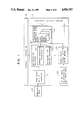
FIG. 1 is a block diagram schematically showing the configuration of an embodiment according to the present invention;
FIG. 2 is a flowchart useful to explain the operation of the embodiment of FIG. 1;
FIGS. 3 to 5 are schematic diagrams for explaining data of work processes in a case of a numeric control cutting work simulator;
FIGS. 6, 7(a) and 7(b) are schematic diagrams for explaining data of work processes in a case of an electric discharge machining simulator;
FIG. 8 is a diagram showing a configuration example of means for storing elimination work space data in a case where an external file is employed;
FIG. 9 is a diagram showing a configuration example of means for storing elimination work space data in a case where an internal memory is employed;
FIG. 10 is a schematic diagram useful to explain the operation of a graphic display processor;
FIG. 11 is a block diagram showing the configuration of an alternative embodiment according to the present invention in a case where the contour model is represented by use of an octtree;
FIG. 12 is a schematic block diagram showing the configuration of an alternative embodiment according to the present invention in a case where the contour model is constituted by use of the boundary representation (B-rep);
FIGS. 13(a), 13(b) and 14(a), 14(b) are flowcharts useful to explain operations of the embodiments of FIGS. 11 and 12, respectively;
FIG. 15 is a flowchart for explaining the operation of the embodiment of FIG. 12 in a case where the graphic display is provided with a Z buffer;
FIG. 16 is block diagram showing the configuration of an alternative embodiment according to the present invention in which intermediate results can be preserved;
FIG. 17 is a schematic diagram showing a configuration example of means for storing work object space data in the embodiment of FIG. 16;
FIGS. 18 and 19 are diagrams useful to explain data in machining work processes in the embodiment of FIG. 16; and
FIG. 20 is a flowchart for explaining the operation of a conventional apparatus.
DESCRIPTION OF THE PREFERRED EMBODIMENTS
Referring now to the drawings, description will be given of an embodiment according to the present invention.
FIG. 1 is a block diagram showing a configuration example of an elimination work simulator as an embodiment according to the present invention, The constitution of FIG. 1 includes initial value data 100 of a work object space, data 101 representing a work operation, a work space data generator 11; a set operation processor 12, elimination work space data store means 131 as the second store means, work object space data store means 132 as the first store means, a graphic display processor 14; and a system controller 15 to control these components above. In addition, the set operation processor 12 comprises a product operation processor 121 and a difference operation processor 122.
Furthermore, the space data to be handled here is of n dimensions (n≧2).
FIG. 2 is a flowchart for explaining the operation of the embodiment of FIG. 1. Referring next to FIG. 2, description will be given of a flow of the processing in the elimination work simulator of the embodiment of FIG. 1. Assume here that when a work is effected through m work operation units of a working or machining device, work object space data associated with a work object in the j-th work operation unit is Wj-1, work space data corresponding to a space through which the machining device passes is represented as Tj, and elimination work space data associated with the elimination of the work object space by the machining device is Cj, where j indicates an order number of the work operation unit assigned to the machining operation j.
(1) First, in step D20 of FIG. 2, a value W0 of the initial data 100 associated with the work object space of FIG. 1 is inputted to the work object space data store means 132.
(2) Next, in step D21, control is transferred to processing related to each work operation unit j. First, in step D22, operation data of the work operation unit j is inputted to generate work space data Tj.
(3) Thereafter, in step D23, a product is computed between the work object space data Wj-1 and the work space data Tj produced in the step D22, and then the product result is outputted to the elimination work space data store means 131 for an addition of the data. In addition, in parallel with the processing of the step D23, a difference is computed between the work object space data Wj-1 and the work space data Tj generated in the step D22 so as to assume the result to be the work object space data Wj of the present work operation unit.
(4) Furthermore, in step D26, the content of the work object space data Wj-1 of the preceding work operation unit in the work object space data store means 132 is updated to be the content of Wj thus produced. Thereafter, the value of j is updated in the step D21 and then control is passed to processing related to the next work operation unit. When the processing above is completed for all work operation units, the work object space data store means 132 is as a result loaded with the final work result Wm, whereas the elimination work space data Cj (j=1, m) of all work operation units are accumulated in the elimination work space data store means 131.
(5) In step D27, the worked or machined state of the work object is displayed by use of the data stored in the two store means. Moreover, if a step D28 to display Wj is added so as to follow the step D26, the display processing is also achieved together with the set operation.
Next, description will be given of a case where a numeric control machining work is simulated by use of the elimination work simulator of FIG. 1. In this situation, the work object space is a contour of a raw material or workpiece, the work operation unit corresponds to a numeric control instruction block, a machining device is a machine tool, and the work space is associated with a tool envelope body comprising a space through which the tool passes during the 1-block operation. FIG. 3 shows a data example associated with a set operation processing in the apparatus of the embodiment. For simplification of explanation, it is assumed here that the contour as the object of the work is of two dimensions and the number of the working or machining operations is four.
Referring next to FIG. 3, description will be given of the processing in the apparatus of the embodiment. In (a) to (e) of FIG. 3, W0 is the processing data 100 of the work object space of FIG. 1 and represents the initial data of the contour of the raw material. Next, control is passed to a work operation of block 1. First, the tool locus data T1 generated by the work space data generator 11 and W0 are respectively subjected to the product operation W0 ∩T1 and the difference operation W0 -T1 in the product operation processor 121 and the difference operation processor 122 of FIG. 1. The result of the product operation is then supplied to the elimination work space data store means 131; whereas the result of the difference operation is outputted as the latest work object space data to the work object space data store means 132. The processing associated with the second and subsequent blocks is accomplished by repeatedly effecting the operation above. As a result, the elimination work space data of FIG. 4 is stored in the elimination work space data store means 131; whereas the final work result of FIG. 5 is accumulated in the work object space data store means 132.
Next, description will be given of a case where the elimination work simulator is applied to an electric discharge machining. In this case, the work unit is to be effected in a predetermined fixed period of time determined and the work space corresponds to a space occupied by the tool electrode and the gap between the tool electrode and the raw material as shown in FIG. 6. In (a) and (b) of FIG. 7, there are shown an operation example of the simulation of the electric discharge machining effected from time i to time i+1. Assuming in (a) of FIG. 7 that the work object space as a result of the cutting operation of the work space Ti at time i is Wi and that the work space Ti+1 effects a machining operation on Wi at time i+1, the product between Wi and Ti+1 is denoted as the elimination work space data Ci+1 and the new work object space is represented as Wi+1.
Next, description will be given of two embodiments associated with the elimination work space data store means 131 of FIG. 1. FIG. 8 shows an embodiment of the elimination work space data store means including a directory file 59 and m elimination work space data files 60. In this embodiment, the respective elimination work space data Cj (j=1, m) are controlled by use of the directory file 59. Since an external storage is adopted in this embodiment, there is attained an effect that the system can cope with an increased amount of data, for example, in a case where a great amount of contour data is produced.
In addition, FIG. 9 shows an alternative embodiment of the elimination work space data store means 131 implemented in a memory integrated in a computer. In this embodiment, there is disposed a table area 61 for controlling the elimination work space data such that pointers to a data area 62 representing the respective contour data are disposed in the table area 61. Although the amount of data to be processed is limited in this embodiment, there is attained an effect that the data can be accessed at a high speed when the data amount is small.
Next, an operation example of the graphic display processor 14 is shown in FIG. 10 in which the worked state of the first block is displayed again by use of the elimination work space data of FIG. 4 and the work object space data of FIG. 5. This display can be achieved by computing the sum of sets between the final work result W4 and the elimination work space data C2, C3, and C4 associated with the first and subsequent blocks.
Next, description will be given of the set operation processor according to the present invention and an alternative embodiment of the graphic display processor.
FIG. 11 is a block diagram showing a configuration example including the set operation processor 12 in which the contours associated with the work object space data and the work space data are represented by use of an octtree model, the two data store means 131 and 132, and the graphic display processor 14. In this embodiment, the set operation processor 12 includes an octtree product operation processor 30 and an octtree difference operation processor 31, the two data store means 131 and 132 of FIG. 11 are respectively an octtree elimination work space data store means 32 and an octtree work object space data store means 33, and the graphic display processor 14 comprises an octtree union operation processor 34 and an octtree display processor 35. Incidentally, the octtree model has been described, for example, in pages 129 to 147 of the Computer Graphics And Image Processing 19, (1982).
Referring now to the flowchart of FIG. 13(a), description will be given of a flow of the processing in a case where the display is effected in the forward direction by use of the graphic display processor.
(1) First, j=1 is set in step E40, and then in step E41, the sum of sets or union is computed between the final work result Wm and the elimination work space data Ci (i=1, m) associated with the work operation units 1 to m by use of the octtree union operation processor 34 of FIG. 11, and then the result of the union is displayed in step E42. The display operation is accomplished by the octtree display processor 35, thereby displaying the first work object space data.
(2) Next, the value of j is updated to be j=2 in the step E40 so as to compute the sum of sets between the final work result Wm and the elimination work space data Ci (i=2, m) associated with the work operation units 2 to m, and then the result is displayed, thereby displaying the work result of the first work operation. Subsequently, the operations above are repeatedly achieved to implement the forward-directional display.
Next, referring to the flowchart of FIG. 13(b), description will be given of a flow of processing of the backward-directional display.
(1) First, in step E45, the final work result Wm accumulated in the octtree work object space data store means 33 is displayed by use of the octtree display processor 35.
(2) Next, in step E47, the union is computed between the elimination work space data Cm of the work operation unit m stored in the octtree elimination work space data store means 32 and the final work result Wm, and then the result of the union is displayed by use of the octtree display processor 35, thereby displaying the work object space data Wm-1 of the (m-1)-th operation.
(3) Subsequently, the value of j is updated in the step E46, and then in step E47, the unions of Wm and Cm above and the elimination work space data Cm-1 of the work operation unit (m-1) are respectively computed so as to display the result in the step E48, thereby displaying the work object space data Wm of the (m-2)-th work operation. Subsequently, the back-ward-directional display can be implemented by repeatedly achieving the operations above.
In this embodiment, there is required the processing to compute the sum of sets between the octtree work object space data Wm and the octtree elimination work space data Cj (j=1, m); however, since Wm and Cj (j=1, m) are spaces which are mutually prime, the processing to attain the union can be accomplished at a very high speed. In consequence, the animation display in the forward and backward directions can be effected at a high speed.
Next, description will be given of an alternative embodiment according to the present invention in a case where the contour data is represented by use of the boundary representation (B-rep). The boundary representation, B-rep has been described, for example, in pages 88 to 90 of the Methodology of Automatic Design written by Norio Okino (Yokendo, 1982).
FIG. 12 shows a configuration example of the contour data according to the boundary representation in which the set operation processor includes a B-rep product operation processor 36 and a B-rep difference operation processor 37, the data store means comprises a B-rep elimination work space data store means 38 and a B-rep work object space data store means 39, and the graphic display processor 14 includes a display patch generator 40 to generate a group of display patches from B-rep data, a patch selector 41 to select a group of patches therefrom for the display, and a patch display processor 42.
Referring now to the flowchart of FIG. 14(a), description will be given of an operation example in a case where the forward-direction display is accomplished in an elimination work simulator having the apparatus of FIG. 12.
(1) In steps F50 and F51, the final work result Wm and the elimination work space data Cj (j=1, m) in the boundary representation are converted into groups of display patches. The conversion is effected by the display patch group generator 40 of FIG. 12.
(2) Next, j=1 is set in step F54. In the subsequent step F52, the sum of sets is computed between Wm and Ci (i=j, m) in the form of converted patch groups such that a group of patches constituting the surfaces of the space represented by the sum of sets is selected by the display patch group selector 41 of FIG. 12. The selected patches are subjected to a concealed surface processing so as to be displayed in the patch display processor 42. However, since Wm and Ci (i=j, m) are spaces which are mutually prime, the operation to compute the sum of sets is not actually necessary, namely, surface patch data of the respective spaces need only be appropriately selected.
(3) In the step F54, the value of j is updated so as to repeatedly achieve the operations above, thereby effecting the forward-directional display.
FIG. 14(b) shows an operation example of the backward-directional display. In this flowchart, the processing from the step F50 to the step F53 to obtain a group of display patches through a conversion and to select a display patch group therefrom for the display thereof is the same as that of FIG. 14(a). For the backward-directional display, the update method of the value of j in the step F55 of FIG. 14(b) is reversed as compared with that employed in the step F54 of FIG. 14(a). The method of computing the sets is here also the same as that used in FIG. 14(a).
According to the embodiment, since the worked or machined state is traced only through an appropriate selection of surface patches associated with Wm and Ci (i=j, m) which are mutually prime, the animation display in the forward and backward directions can be accomplished at a high speed.
FIG. 15 is a flowchart showing a backward directional display in a case where the graphic display processor includes a Z buffer so as to effect a concealed surface erase processing mechanism. According to the embodiment, owing to the characteristic of the Z buffer concealed surface processing method like that described in pages 186 to 188 of the Basic Graphic written by Kawai (Shokodo, 1985), an image as a result of the union operation can be automatically attained only by sequentially superimposing Ci (i=m,j) onto Wm in the drawing operation, the animation display of the worked state in the backward direction can be achieved at a very high speed.
FIG. 16 is a block diagram showing an alternative embodiment according to the present invention in a case where not only the final work result Wm but also the work object space data as intermediate results of the work or machine operation are preserved. In the embodiment of FIG. 16, as compared with the work object space data store means 132 of FIG. 1, there is included work object space data store means 133 designed with considerations of an accumulation of several work object space data items Wi as intermediate work results. FIG. 17 shows an embodiment of a store method of storing the work object space data items Wi in which several work object space data Wi in the work object space data store means 133 are controlled by means of a directory file 62. In addition, FIG. 18 shows data finally accumulated in the work object space data store means 133 when the processing similar to that described in conjunction with FIG. 3 is achieved by use of the simulator of FIG. 15 so as to preserve the work object space data of the second block. Furthermore, FIG. 19 is a display example of the work object space at an intermediate point of the machine work, the display implemented by use of the accumulated data. It can be seen from FIG. 19 that the display of W1 can be accomplished by use of C2 selected from the elimination work space data Cj (j=1, 4) of FIG. 4 and the work object space data W2 of FIG. 18.
In this embodiment, as compared with a case where the work object space data at intermediate points of the work is not preserved, the number of elimination work space data items as an object of the display is decreased; consequently, the display operation can be accordingly effected at a higher speed. In addition, when compared with a case where Wj of all work operation units are to be preserved, the capacity of the storage necessary for the operation is reduced, and hence there is implemented a system advantageous in two points, namely, the speed and the data amount, which leads to an effect that the animation display in the forward and backward directions can be accomplished at a very high speed.
According to the present invention, as described above, the work information accumulated in the apparatus includes the work object space data in the final operation units of the machining device and the elimination work space data of all work operation units and the space data items are mutually prime; in consequence, when compared with a method in which the work object space data of all work operation units are to be accumulated, there is attained an effect that the amount of the accumulated data is minimized.

Claims (20)

We claim:
1. An elimination work simulator in which a work is achieved through m operation units comprising:
a first set operation processor for respectively generating a difference space between an n-dimensional work object space date Wj-1 corresponding to a work object in a jth work operation unit from among j operation units, where j=1, 2, . . . , m, and an n-dimensional work space data Tj corresponding to a space through which a machining device passes in the jth work operation unit in order to provide a difference space respectively corresponding to each of the operation units, wherein n is an integer greater than or equal to 2;
first store means for storing the difference spaces as new work object space data Wj;
a second set operation processor for respectively generating a product space between the work object space data Wj-1 and the work space data Tj in order to provide a product space respectively corresponding to each of the operation units; and
second store means for sequentially storing the product spaces as elimination work space data Cj.
2. An elimination work simulator according to claim 1, wherein the new work object space data Wj is used to update the work object space data Wj-1.
3. An elimination work simulator according to claim 1, wherein the work object space data Wj is stored in association with a plurality of work operation units.
4. An elimination work simulator in which a work is achieved through m operation units comprising:
a first set operation processor for respectively generating a difference space between an n-dimensional work object space data Wj-1 corresponding to a work object in a jth work operation unit from among j operation units, where j=1,2 . . . m, and an n-dimensional work space data Tj corresponding to a space through which a machining device passes in the jth work operation unit in order to provide a difference space respectively corresponding to each of the operation units wherein n is an integer greater than or equal to 2;
first store means for storing the difference spaces as new work object space data Wj;
a second set operation processor for respectively generating a product space between the work object space data Wj-1 and the work space data Tj in order to provide a product space respectively corresponding to each of the operation units;
second store means for sequentially storing the product spaces as elimination work space data Cj; and
a graphic display processor for displaying work object space data Wk-1 in an arbitrary work operation unit k, where k≦j, by use of the new work object space data Wj stored in said first store means and at least a portion of a group of elimination work space data Ci, where i≦j, previously stored in said second store means.
5. An elimination work simulator according to claim 4, wherein said set operation processors, said store means, and said graphic display processor are respectively octtree apparatuses.
6. An elimination work simulator according to claim 4, wherein the work space data Tj is represented through use of a boundary representation model.
7. An elimination work simulator according to claim 4, wherein an animation display of the work object space data Wj is effected in an order corresponding to a performance order of performed work operations.
8. An elimination work simulator according to claim 4, wherein an animation display of the work object space data Wj is effected in an order corresponding to a reverse performance order of performed work operations.
9. An elimination work simulator according to claim 1, wherein said second store means accumulates said sequentially stored product spaces.
10. An elimination work simulator according to claim 4, wherein said second store means accumulates said sequentially stored product spaces.
11. An elimination process simulator for simulating a process involving m operations comprising:
a first set operation processor for respectively generating a remainder portion data representing a remainder portion corresponding to an n-dimensional work object to be processed in a jth operation from among j operations, where j= 1, 2, . . . , m, less an n-dimensional work object portion corresponding to a space through which a machining device passes in the jth operation in order to provide a remainder portion data respectively corresponding to each of the operations, wherein n is an integer greater than or equal to 2;
first store means for storing the remainder portion data corresponding to each of the operation units as updated remainder portion data;
a second set operation processor for respectively generating an overlap portion data representing an overlap portion corresponding to an intersection between the n-dimensional work object to processed in the jth operation and the space through which the machining device passes in the jth operation in order to provide an overlap portion data respectively corresponding to each of the operations; and
second store means for sequentially storing the overlap portion data as elimination work space data Cj.
12. An elimination process simulator according to claim 11, wherein the updated remainder portion data is used to update the remainder portion data.
13. An elimination process simulator according to claim 11, wherein the remainder portion data is stored in association with a plurality of work operations.
14. An elimination processor simulator for simulating a process involving m operations comprising:
a first set operation processor for respectively generating a remainder portion data representing a remainder portion corresponding to an n-dimensional work object to be processed in a jth operation from among j operations, where j= 1, 2, . . . , m, less an n-dimensional work object portion corresponding to a space through which a machining device passes in the jth operation in order to provide a remainder portion data respectively corresponding to each of the operation, wherein n is an integer greater than or equal to 2;
first store means for storing the reminder portion data corresponding to each of the operation units as updated remainder portion data;
a second set operation processor for respectively generating an overlap portion data representing an overlap portion corresponding to an intersection between the n-dimensional work object to be processed in the jth operation and the space through which the machining device passes in the jth operation in order to provide an overlap portion data respectively corresponding to each of the operations;
second store means for sequentially storing the overlap portion data as elimination work space data Cj; and
a graphic display processor for displaying an n-dimensional work object to be processed in a kth operation, where k is an integer less than or equal to j, by using the updated remainder portion data stored in said first store means and at least a portion of elimination work space data Ci, where i is an integer less than or equal to j, previously stored in said second store means.
15. An elimination process simulator according to claim 14, wherein said set operation processors, said store means, and said graphic display processor are respectively octtree apparatuses.
16. An elimination process simulator according to claim 14, wherein the data corresponding to the space through which the machining device passes in the jth operation is represented by using a boundary representation solid model.
17. An elimination process simulator according to claim 14, wherein an animation display of the updated remainder portion data is effected in an order corresponding to a performance order of the work operations.
18. An elimination process simulator according to claim 14, wherein an animation display of the updated remainder portion data is effected in an order corresponding to a reverse performance order of the work operations.
19. An elimination process simulator according to claim 11, wherein said second store means accumulates said sequentially stored overlap portion data.
20. An elimination process simulator according to claim 14, wherein said second store means accumulates said sequentially stored overlap portion data.
US07/243,640 1987-09-21 1988-09-13 Elimination work simulator apparatus Expired - Fee Related US4956787A (en)

Applications Claiming Priority (2)

Application Number Priority Date Filing Date Title
JP62234988A JPH0752366B2 (en) 1987-09-21 1987-09-21 Pest control simulator
JP62-234988 1987-09-21

Publications (1)

Publication Number Publication Date
US4956787A true US4956787A (en) 1990-09-11

Family

ID=16979390

Family Applications (1)

Application Number Title Priority Date Filing Date
US07/243,640 Expired - Fee Related US4956787A (en) 1987-09-21 1988-09-13 Elimination work simulator apparatus

Country Status (4)

Country Link
US (1) US4956787A (en)
EP (1) EP0308727B1 (en)
JP (1) JPH0752366B2 (en)
DE (1) DE3882315T2 (en)

Cited By (15)

* Cited by examiner, † Cited by third party
Publication number Priority date Publication date Assignee Title
US5121333A (en) * 1989-06-09 1992-06-09 Regents Of The University Of Minnesota Method and apparatus for manipulating computer-based representations of objects of complex and unique geometry
US5128870A (en) * 1989-06-09 1992-07-07 Regents Of The University Of Minnesota Automated high-precision fabrication of objects of complex and unique geometry
US5184306A (en) * 1989-06-09 1993-02-02 Regents Of The University Of Minnesota Automated high-precision fabrication of objects of complex and unique geometry
US5257203A (en) * 1989-06-09 1993-10-26 Regents Of The University Of Minnesota Method and apparatus for manipulating computer-based representations of objects of complex and unique geometry
US5274574A (en) * 1990-02-19 1993-12-28 Mitsubishi Denk K.K. Dynamic simulation system
US5293106A (en) * 1989-12-11 1994-03-08 Murata Kikai Kabushiki Kaisha Program reviewing device in numerical control processing apparatus
US5325308A (en) * 1991-07-25 1994-06-28 Okuma Corporation Simulation method of machining steps
US5440697A (en) * 1991-10-23 1995-08-08 International Business Machines Corporation Method and apparatus for simulating I/O devices
US5475799A (en) * 1988-04-07 1995-12-12 Matsushita Electric Industrial Co., Ltd. Method of modeling shapes using a combination of different shapes to represent the resultant shape
US5526479A (en) * 1990-06-25 1996-06-11 Barstow; David Method and apparatus for broadcasting live events to another location and producing a computer simulation of the events at that location
US5561747A (en) * 1992-02-03 1996-10-01 Computervision Corporation Boundary evaluation in non-manifold environment
US5581489A (en) * 1994-01-05 1996-12-03 Texas Instruments Incorporated Model generator for constructing and method of generating a model of an object for finite element analysis
US5703782A (en) * 1987-07-28 1997-12-30 Dundorf; David M. Method and system for producing 3-D carred signs using automatic tool path generation and computer-simulation techniques
US7373587B1 (en) 1990-06-25 2008-05-13 Barstow David R Representing sub-events with physical exertion actions
US10521724B2 (en) 2016-04-28 2019-12-31 Fanuc Corporation Numerical controller with swarf removal calculations

Families Citing this family (2)

* Cited by examiner, † Cited by third party
Publication number Priority date Publication date Assignee Title
ATE124795T1 (en) * 1990-09-18 1995-07-15 Grundig Ag METHOD FOR SIMULATING THE MACHINING OF WORKPIECES.
JP2697303B2 (en) * 1990-11-28 1998-01-14 松下電器産業株式会社 3D machine

Citations (8)

* Cited by examiner, † Cited by third party
Publication number Priority date Publication date Assignee Title
GB2140937A (en) * 1983-05-10 1984-12-05 Philips Nv Simulation of machine tools
EP0129091A2 (en) * 1983-05-23 1984-12-27 Mitsubishi Denki Kabushiki Kaisha Numerical control system, graphics display unit and machine tool
EP0153556A2 (en) * 1984-01-13 1985-09-04 Dr. Johannes Heidenhain GmbH Method for graphical presentation of drawings
EP0166783A1 (en) * 1983-12-14 1986-01-08 Fanuc Ltd. Machining step determination method for automatic programming
US4736306A (en) * 1985-04-29 1988-04-05 The United States Of America As Represented By The United States Department Of Energy System for conversion between the boundary representation model and a constructive solid geometry model of an object
US4791579A (en) * 1983-10-26 1988-12-13 Dr. Johannes Heidenhain Gmbh Process and apparatus for graphically representing a variable structure in perspective
US4792889A (en) * 1986-05-17 1988-12-20 Dr. Johannes Heidenhain Gmbh Device and method for determining workpiece contours
US4833617A (en) * 1987-08-14 1989-05-23 General Electric Company Solid modeling based adaptive feedrate control for NC machining

Patent Citations (9)

* Cited by examiner, † Cited by third party
Publication number Priority date Publication date Assignee Title
GB2140937A (en) * 1983-05-10 1984-12-05 Philips Nv Simulation of machine tools
EP0129091A2 (en) * 1983-05-23 1984-12-27 Mitsubishi Denki Kabushiki Kaisha Numerical control system, graphics display unit and machine tool
US4791579A (en) * 1983-10-26 1988-12-13 Dr. Johannes Heidenhain Gmbh Process and apparatus for graphically representing a variable structure in perspective
EP0166783A1 (en) * 1983-12-14 1986-01-08 Fanuc Ltd. Machining step determination method for automatic programming
EP0153556A2 (en) * 1984-01-13 1985-09-04 Dr. Johannes Heidenhain GmbH Method for graphical presentation of drawings
US4757461A (en) * 1984-01-13 1988-07-12 Dr. Johannes Heidenhain Gmbh Process for graphically representing a structure
US4736306A (en) * 1985-04-29 1988-04-05 The United States Of America As Represented By The United States Department Of Energy System for conversion between the boundary representation model and a constructive solid geometry model of an object
US4792889A (en) * 1986-05-17 1988-12-20 Dr. Johannes Heidenhain Gmbh Device and method for determining workpiece contours
US4833617A (en) * 1987-08-14 1989-05-23 General Electric Company Solid modeling based adaptive feedrate control for NC machining

Non-Patent Citations (8)

* Cited by examiner, † Cited by third party
Title
Kawai Basic Graphics Shokodo pp. 186 188; 1985. *
Kawai-"Basic Graphics"-Shokodo-pp. 186-188; 1985.
Meacher Geometric Modeling Using Octree Encoding Computer Graphics and Image Processing 19, pp. 129 147; Academic Press; 1982. *
Meacher-"Geometric Modeling Using Octree Encoding"-Computer Graphics and Image Processing 19, pp. 129-147; Academic Press; 1982.
Okino Methodology of Automatic Design Yokendo; pp. 88 90, 133, 134; 1982. *
Okino-"Methodology of Automatic Design"-Yokendo; pp. 88-90, 133, 134; 1982.
Van Hook Real Time Shaded NC Milling Display ACM Siggraph, vol. 20, No. 4, pp. 15 20; 1986. *
Van Hook-"Real-Time Shaded NC Milling Display"-ACM Siggraph, vol. 20, No. 4, pp. 15-20; 1986.

Cited By (19)

* Cited by examiner, † Cited by third party
Publication number Priority date Publication date Assignee Title
US6459952B1 (en) 1987-07-28 2002-10-01 David M. Dundorf Method of and system for producing 3-D carved signs using automatic tool path generation and computer-simulation techniques
US5703782A (en) * 1987-07-28 1997-12-30 Dundorf; David M. Method and system for producing 3-D carred signs using automatic tool path generation and computer-simulation techniques
US5475799A (en) * 1988-04-07 1995-12-12 Matsushita Electric Industrial Co., Ltd. Method of modeling shapes using a combination of different shapes to represent the resultant shape
US5128870A (en) * 1989-06-09 1992-07-07 Regents Of The University Of Minnesota Automated high-precision fabrication of objects of complex and unique geometry
US5184306A (en) * 1989-06-09 1993-02-02 Regents Of The University Of Minnesota Automated high-precision fabrication of objects of complex and unique geometry
US5257203A (en) * 1989-06-09 1993-10-26 Regents Of The University Of Minnesota Method and apparatus for manipulating computer-based representations of objects of complex and unique geometry
US5121333A (en) * 1989-06-09 1992-06-09 Regents Of The University Of Minnesota Method and apparatus for manipulating computer-based representations of objects of complex and unique geometry
US5293106A (en) * 1989-12-11 1994-03-08 Murata Kikai Kabushiki Kaisha Program reviewing device in numerical control processing apparatus
US5274574A (en) * 1990-02-19 1993-12-28 Mitsubishi Denk K.K. Dynamic simulation system
US5526479A (en) * 1990-06-25 1996-06-11 Barstow; David Method and apparatus for broadcasting live events to another location and producing a computer simulation of the events at that location
US5671347A (en) * 1990-06-25 1997-09-23 Barstow; David R. Method and apparatus for broadcasting live events to another location and producing a computer simulation of the events at that location
US6204862B1 (en) * 1990-06-25 2001-03-20 David R. Barstow Method and apparatus for broadcasting live events to another location and producing a computer simulation of the events at that location
US7373587B1 (en) 1990-06-25 2008-05-13 Barstow David R Representing sub-events with physical exertion actions
US20080209307A1 (en) * 1990-06-25 2008-08-28 Barstow David R Representing sub-event with physical exertion actions
US5325308A (en) * 1991-07-25 1994-06-28 Okuma Corporation Simulation method of machining steps
US5440697A (en) * 1991-10-23 1995-08-08 International Business Machines Corporation Method and apparatus for simulating I/O devices
US5561747A (en) * 1992-02-03 1996-10-01 Computervision Corporation Boundary evaluation in non-manifold environment
US5581489A (en) * 1994-01-05 1996-12-03 Texas Instruments Incorporated Model generator for constructing and method of generating a model of an object for finite element analysis
US10521724B2 (en) 2016-04-28 2019-12-31 Fanuc Corporation Numerical controller with swarf removal calculations

Also Published As

Publication number Publication date
EP0308727A2 (en) 1989-03-29
DE3882315T2 (en) 1994-01-27
JPH0752366B2 (en) 1995-06-05
DE3882315D1 (en) 1993-08-19
JPS6479805A (en) 1989-03-24
EP0308727A3 (en) 1989-05-10
EP0308727B1 (en) 1993-07-14

Similar Documents

Publication Publication Date Title
US4956787A (en) Elimination work simulator apparatus
US5734806A (en) Method and apparatus for determining graphical object visibility
EP0319787B1 (en) Parallel rendering of smoothly shaded color triangles with anti-aliased edges for a three dimensional color display
KR890002005B1 (en) Process for graphically representing a variable structure in perspective
JPH04506717A (en) Pipelined Single Port Z - An Efficient Way to Update Buffers
US5101363A (en) Method and apparatus for simulating the processing of a workpiece
JP2618951B2 (en) 3D graphics processor
JPH0687267B2 (en) Wire frame graphic display generation method and device and hidden line removal system
JPH07175507A (en) Method and method for numerically controlled machining simulation based upon nonmanifold body data structure
US4961072A (en) Graphics display method for numerical control apparatus
US5537520A (en) Method and system for displaying a three dimensional object
JPH03240806A (en) Dynamic simulation system
EP0803797A1 (en) System for use in a computerized imaging system to efficiently transfer graphic information to a graphics subsystem employing masked span
KR100382108B1 (en) 3D graphic accelerator and method for processing graphic acceleration using the same
JP2926644B2 (en) Processing simulation method
Wallis et al. Creating large solid models for NC toolpath verification
KR0165464B1 (en) Apparatus and method of span rendering for graphics
JP2786340B2 (en) Machining time calculation method in numerical control information creation device
JP3267536B2 (en) 3D image processing device
JPS62188647A (en) Drawing method for tool locus of combined curved surface
JPH0431400B2 (en)
JPH04119484A (en) Method and device for displaying drawing for three-dimensional shape
JPH07114369A (en) Character and graphite data processor
JPH0589250A (en) System for painting out two-dimensional figure
JPH0754551B2 (en) Polygon filling device

Legal Events

Date Code Title Description
AS Assignment

Owner name: HITACHI, LTD., 6, KANDA SURUGADAI 4-CHOME, CHIYODA

Free format text: ASSIGNMENT OF ASSIGNORS INTEREST.;ASSIGNORS:ITO, KUMIKO;KAWASHIMA, YASUMASA;NONAKA, SHIRO;AND OTHERS;REEL/FRAME:004935/0105

Effective date: 19880830

FEPP Fee payment procedure

Free format text: PAYOR NUMBER ASSIGNED (ORIGINAL EVENT CODE: ASPN); ENTITY STATUS OF PATENT OWNER: LARGE ENTITY

FPAY Fee payment

Year of fee payment: 4

FPAY Fee payment

Year of fee payment: 8

REMI Maintenance fee reminder mailed
LAPS Lapse for failure to pay maintenance fees
STCH Information on status: patent discontinuation

Free format text: PATENT EXPIRED DUE TO NONPAYMENT OF MAINTENANCE FEES UNDER 37 CFR 1.362

FP Lapsed due to failure to pay maintenance fee

Effective date: 20020911