US4966392A - Wheelchair and occupant restraints - Google Patents
Wheelchair and occupant restraints Download PDFInfo
- Publication number
- US4966392A US4966392A US07/349,103 US34910389A US4966392A US 4966392 A US4966392 A US 4966392A US 34910389 A US34910389 A US 34910389A US 4966392 A US4966392 A US 4966392A
- Authority
- US
- United States
- Prior art keywords
- harness
- anchor
- strap
- buckle
- chair
- Prior art date
- Legal status (The legal status is an assumption and is not a legal conclusion. Google has not performed a legal analysis and makes no representation as to the accuracy of the status listed.)
- Expired - Fee Related
Links
Images


Classifications
-
- A—HUMAN NECESSITIES
- A61—MEDICAL OR VETERINARY SCIENCE; HYGIENE
- A61G—TRANSPORT, PERSONAL CONVEYANCES, OR ACCOMMODATION SPECIALLY ADAPTED FOR PATIENTS OR DISABLED PERSONS; OPERATING TABLES OR CHAIRS; CHAIRS FOR DENTISTRY; FUNERAL DEVICES
- A61G3/00—Ambulance aspects of vehicles; Vehicles with special provisions for transporting patients or disabled persons, or their personal conveyances, e.g. for facilitating access of, or for loading, wheelchairs
- A61G3/08—Accommodating or securing wheelchairs or stretchers
- A61G3/0808—Accommodating or securing wheelchairs
-
- Y—GENERAL TAGGING OF NEW TECHNOLOGICAL DEVELOPMENTS; GENERAL TAGGING OF CROSS-SECTIONAL TECHNOLOGIES SPANNING OVER SEVERAL SECTIONS OF THE IPC; TECHNICAL SUBJECTS COVERED BY FORMER USPC CROSS-REFERENCE ART COLLECTIONS [XRACs] AND DIGESTS
- Y10—TECHNICAL SUBJECTS COVERED BY FORMER USPC
- Y10S—TECHNICAL SUBJECTS COVERED BY FORMER USPC CROSS-REFERENCE ART COLLECTIONS [XRACs] AND DIGESTS
- Y10S297/00—Chairs and seats
- Y10S297/04—Wheelchair
Definitions
- This invention relates to the restraint of a wheelchair or like seat (hereinafter called a "chair") and its occupant in the event that the chair with its occupant are to be transported by means of a vehicle (including aircraft) or some either conveyance susceptible of very high, if transitory, accelerations (including decelerations) as in the case of an accident involving the vehicle.
- a vehicle including aircraft
- a typical system includes two front and two rear anchor points on the platform, to which points the chair is fastened, such as by straps e.g. webbing belts, with the seating reference plane at right angles to the platform and parallel to its direction of motion.
- straps e.g. webbing belts
- the anchor points are symmetrically disposed with respect to the seating reference plane and are transversely spaced by a distance substantially equal to the width of the chair.
- the front and rear anchor points may be longitudinally spaced by an adjustable distance, which may depend on the length and type of chair, and/or the lengths of the front and/or rear straps may be adjustable.
- An object of the invention is to provide a very safe and relatively simple system for restraining a wheelchair and its occupant on what may for convenience by described as a movable platform, which may be, for example, the floor of a vehicle.
- Another object is to provide a system which complies with a typically stringent governmental standard e.g. Australian Standard 2942-1987 "Wheelchair Occupant Restraint Assemblies for Motor Vehicles”.
- the present invention provides a safety harness for a wheelchair/occupant system being or to be transported on a movable platform liable to sudden stoppage or other potentially dangerous rearward impulse, the platform having associated therewith rear anchor means to which the harness is adapted to secure the system, said harness including a lap belt for the occupant and on each side of the chair a buckle providing a connexion movable relative to the system, said buckle being connected or connectible to the nearer end of the lap belt, an anchor strap tending to pull the buckle downwardly and rearwardly, and a holding strap associated with the anchor strap but connected or connectible to a forward part of the buckle via a chair part so that the buckle is pulled forwardly in response to decelerating forces applied direct to the chair via the holding strap.
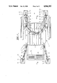
- FIG. 1 is a top plan view of a wheelchair (occupant not shown) secured or harnessed to the floor of a vehicle in accordance with a practical embodiment of the invention
- FIG. 2 is perspective showing the left front strap connection of the harness shown in FIG. 1;
- FIG. 3 is a perspective view of a floor baseplate forming part of front and rear anchors for the harness shown in FIGS. 1 and 2;
- FIG. 4 shows an eyebolt forming part of front and rear anchors for the harness shown in FIGS. 1 and 2, for reception in the baseplate shown in FIG. 3, and
- FIG. 5 is a perspective showing the right rear strap connection of the harness shown in FIG. 1.
- a wheelchair 6 having a seat 7, armrests 8 and footrests 9 for an occupant (not shown).
- the chair and occupant comprise a system of two masses to be inter-harnessed, and also harnessed to platform 9 which may be the floor of a vehicle forwardly movable in the direction indicated by arrow 9A.
- the baseplate unit includes a top plate 15 underneath which is a receptacle 16 for the eyebolt via keyhole aperture 17. Eyebolt 14 is attached to the end of anchor strap 18.
- the baseplate units are bolted or otherwise firmly fastened to floor 9, the lastmentioned being suitably recessed as necessary in order to accommodate the unit, with plate 15 flush with the floor.
- aperture 17 may be automatically closed by a spring-loaded depressor plate (not shown) within receptacle 16.
- the harness includes a lap belt 19 for the occupant and on each side of the chair a buckle 20, 21 in the form of D-shaped clips, providing strap connections which are stable but "floating" i.e. movable relative to chair and/or occupant.
- each buckle is connected to the relevant (i.e. nearer) end of lap belt 19, and to the relevant anchor straps or strap assembly 18 both directly by connection strap 22 and also by holding strap 23 which is passed around chair post 24.
- buckles 20, 21 are generally subject to three forces viz. the connection straps tending to pull the buckles downwardly and rearwardly, the holding straps forwardly and the lap belt upwardly and forwardly. It also appears that the retarding forces which are applied direct to the chair (by holding straps 23 passing around posts 24) also tend to pull the buckles forwardly.
- the anchor strap assemblies may including quick-release clips such as 25 of a kind known per se.
- the strap or belt connections are, wherever possible, effected by looping the strap around the relevant part and using e.g. a quick-release buckle or like attachment to secure the end of the strap back to the strap itself.
- the harness straps or webbing are doubled where a strap is required to pass over a straight metal edge or such other formation as might sever the strap under large forces.
- the rear and/or front straps may incorporate length-adjusting means 26 of a ratchet or other known type. It may suffice for one pair to be so adjustable.
Abstract
Description
Claims (6)
Priority Applications (1)
| Application Number | Priority Date | Filing Date | Title |
|---|---|---|---|
| US07/349,103 US4966392A (en) | 1989-05-09 | 1989-05-09 | Wheelchair and occupant restraints |
Applications Claiming Priority (1)
| Application Number | Priority Date | Filing Date | Title |
|---|---|---|---|
| US07/349,103 US4966392A (en) | 1989-05-09 | 1989-05-09 | Wheelchair and occupant restraints |
Publications (1)
| Publication Number | Publication Date |
|---|---|
| US4966392A true US4966392A (en) | 1990-10-30 |
Family
ID=23370921
Family Applications (1)
| Application Number | Title | Priority Date | Filing Date |
|---|---|---|---|
| US07/349,103 Expired - Fee Related US4966392A (en) | 1989-05-09 | 1989-05-09 | Wheelchair and occupant restraints |
Country Status (1)
| Country | Link |
|---|---|
| US (1) | US4966392A (en) |
Cited By (28)
| Publication number | Priority date | Publication date | Assignee | Title |
|---|---|---|---|---|
| US5044847A (en) * | 1990-02-15 | 1991-09-03 | Queen's Univeristy At Kingston | Positive locking tie-down system |
| US5137413A (en) * | 1990-10-05 | 1992-08-11 | Paul Ressler | Expanded interior space and improved access mini-van |
| US5338048A (en) * | 1993-05-10 | 1994-08-16 | Henry Medina | Collapsible wheelchair |
| US5344265A (en) * | 1992-08-11 | 1994-09-06 | State Of Oregon, Acting By And Through The State Board Of Higher Education On Behalf Of Osu | Securement system for a rollable mobility aid |
| US5391030A (en) * | 1992-10-14 | 1995-02-21 | Lee; Ray | Wheelchair restraint affixment straps |
| US5431524A (en) * | 1994-05-27 | 1995-07-11 | Antal; Donald V. | Vehicle transport trailer |
| US5522404A (en) * | 1992-12-22 | 1996-06-04 | Williams; Rick | Adjustable safety and assistance harnessing devices |
| GB2300158A (en) * | 1995-04-17 | 1996-10-30 | Girardin Jean Marc | Load tiedown system for securing a wheelchair |
| WO1998044887A1 (en) * | 1997-04-09 | 1998-10-15 | Ancra Jungfalk Gmbh | Device for provisionally connecting a fastening strap to an anchor point |
| US6073951A (en) * | 1997-10-06 | 2000-06-13 | Invacare Corporation | Articulating seat/chassis interface for a wheelchair |
| US6154690A (en) * | 1999-10-08 | 2000-11-28 | Coleman; Raquel | Multi-feature automated wheelchair |
| US20050019125A1 (en) * | 2003-05-27 | 2005-01-27 | Panzarella Thomas A. | Device for securing a personal-transport vehicle to a mounting surface |
| US7125022B2 (en) | 2000-04-06 | 2006-10-24 | Henry Medina | Collapsible chair |
| US20080054615A1 (en) * | 2006-09-06 | 2008-03-06 | Coultrup Sherri L | Tactical seatbelt quick release system |
| US7455490B1 (en) | 2004-07-21 | 2008-11-25 | Gregory F Goosen | Wheelchair holding device |
| US20090126179A1 (en) * | 2003-04-11 | 2009-05-21 | Jeffrey Duncan Watters | Vehicle Conversion Assembly and Method of Converting a Vehicle |
| US20090230638A1 (en) * | 2008-03-13 | 2009-09-17 | Monster Medic, Inc. | Stair chair |
| US20110011907A1 (en) * | 2007-07-11 | 2011-01-20 | Freedom Sciences, Llc | Devices for securing personal-transport vehicles to mounting surfaces |
| US20110120341A1 (en) * | 2009-11-06 | 2011-05-26 | Marketing Displays, Inc. | Railway service vehicle having wheelchair restraint |
| US8702177B1 (en) * | 2012-04-10 | 2014-04-22 | Sherry L. Hogue | Shoulder and waist harness for use with a wheelchair |
| US20140271020A1 (en) * | 2013-03-15 | 2014-09-18 | Valeda Company (D/B/A "Q'straint") | Wheelchair Securement System and Device |
| US9079524B2 (en) | 2010-11-17 | 2015-07-14 | Radock Systems, I.P., Llc | Mobility device docking system |
| US9504617B2 (en) | 2014-07-15 | 2016-11-29 | 4One, Llc | Mobility securement system |
| US9585800B2 (en) | 2014-07-15 | 2017-03-07 | 4One, Llc | Mobility securement system |
| US20180200127A1 (en) * | 2017-01-17 | 2018-07-19 | Dale Binkley | Safety Belt System for Paratransit Lifts |
| DE102017003277A1 (en) * | 2017-04-04 | 2018-10-04 | Franz Blum | Adapter clip for perforated wall system |
| US11440440B2 (en) * | 2018-08-08 | 2022-09-13 | Uatc, Llc | Modular autonomous-vehicle interior |
| US11815119B2 (en) | 2017-04-04 | 2023-11-14 | Franz Blum | Perforated wall system and fastening element |
Citations (2)
| Publication number | Priority date | Publication date | Assignee | Title |
|---|---|---|---|---|
| US4688843A (en) * | 1986-03-04 | 1987-08-25 | Hall Donna R | Wheelchair restraint system for vehicle |
| US4728119A (en) * | 1985-08-14 | 1988-03-01 | Trav-L-Chair, Inc. | Travel chair for the elderly and physically handicapped |
-
1989
- 1989-05-09 US US07/349,103 patent/US4966392A/en not_active Expired - Fee Related
Patent Citations (2)
| Publication number | Priority date | Publication date | Assignee | Title |
|---|---|---|---|---|
| US4728119A (en) * | 1985-08-14 | 1988-03-01 | Trav-L-Chair, Inc. | Travel chair for the elderly and physically handicapped |
| US4688843A (en) * | 1986-03-04 | 1987-08-25 | Hall Donna R | Wheelchair restraint system for vehicle |
Cited By (41)
| Publication number | Priority date | Publication date | Assignee | Title |
|---|---|---|---|---|
| US5044847A (en) * | 1990-02-15 | 1991-09-03 | Queen's Univeristy At Kingston | Positive locking tie-down system |
| US5137413A (en) * | 1990-10-05 | 1992-08-11 | Paul Ressler | Expanded interior space and improved access mini-van |
| US5344265A (en) * | 1992-08-11 | 1994-09-06 | State Of Oregon, Acting By And Through The State Board Of Higher Education On Behalf Of Osu | Securement system for a rollable mobility aid |
| US5391030A (en) * | 1992-10-14 | 1995-02-21 | Lee; Ray | Wheelchair restraint affixment straps |
| US5522404A (en) * | 1992-12-22 | 1996-06-04 | Williams; Rick | Adjustable safety and assistance harnessing devices |
| US5338048A (en) * | 1993-05-10 | 1994-08-16 | Henry Medina | Collapsible wheelchair |
| US5431524A (en) * | 1994-05-27 | 1995-07-11 | Antal; Donald V. | Vehicle transport trailer |
| GB2300158A (en) * | 1995-04-17 | 1996-10-30 | Girardin Jean Marc | Load tiedown system for securing a wheelchair |
| US6471454B1 (en) | 1997-04-09 | 2002-10-29 | Ancra Jungfalk Gmbh | Device for provisionally connecting a fastening strap to an anchor point |
| WO1998044887A1 (en) * | 1997-04-09 | 1998-10-15 | Ancra Jungfalk Gmbh | Device for provisionally connecting a fastening strap to an anchor point |
| US6073951A (en) * | 1997-10-06 | 2000-06-13 | Invacare Corporation | Articulating seat/chassis interface for a wheelchair |
| US6154690A (en) * | 1999-10-08 | 2000-11-28 | Coleman; Raquel | Multi-feature automated wheelchair |
| US7125022B2 (en) | 2000-04-06 | 2006-10-24 | Henry Medina | Collapsible chair |
| US20090126179A1 (en) * | 2003-04-11 | 2009-05-21 | Jeffrey Duncan Watters | Vehicle Conversion Assembly and Method of Converting a Vehicle |
| US7854437B2 (en) * | 2003-04-11 | 2010-12-21 | Jeffrey Duncan Watters | Vehicle conversion assembly and method of converting a vehicle |
| US20050019125A1 (en) * | 2003-05-27 | 2005-01-27 | Panzarella Thomas A. | Device for securing a personal-transport vehicle to a mounting surface |
| US7108466B2 (en) | 2003-05-27 | 2006-09-19 | Cook Technologies, Inc. | Device for securing a personal-transport vehicle to a mounting surface |
| US20060269378A1 (en) * | 2003-05-27 | 2006-11-30 | Cook Technologies, Inc. | Device for securing a personal-transport vehicle to a mounting surface |
| US7431546B2 (en) | 2003-05-27 | 2008-10-07 | Cook Technologies, Inc. | Device for securing a personal-transport vehicle to a mounting surface |
| US7455490B1 (en) | 2004-07-21 | 2008-11-25 | Gregory F Goosen | Wheelchair holding device |
| US20080054615A1 (en) * | 2006-09-06 | 2008-03-06 | Coultrup Sherri L | Tactical seatbelt quick release system |
| US7753410B2 (en) | 2006-09-06 | 2010-07-13 | Coultrup Sherri L | Tactical seatbelt quick release system |
| US20110011907A1 (en) * | 2007-07-11 | 2011-01-20 | Freedom Sciences, Llc | Devices for securing personal-transport vehicles to mounting surfaces |
| US20090230638A1 (en) * | 2008-03-13 | 2009-09-17 | Monster Medic, Inc. | Stair chair |
| US7950673B2 (en) * | 2008-03-13 | 2011-05-31 | Monster Medic, Inc. | Stair chair |
| US20110120341A1 (en) * | 2009-11-06 | 2011-05-26 | Marketing Displays, Inc. | Railway service vehicle having wheelchair restraint |
| US8413588B2 (en) * | 2009-11-06 | 2013-04-09 | Marketing Displays, Inc. | Railway service vehicle having wheelchair restraint |
| US9592761B2 (en) | 2010-11-17 | 2017-03-14 | Radock Systems, I.P., Llc | Device and method for securing a mobility device in a vehicle |
| US9079524B2 (en) | 2010-11-17 | 2015-07-14 | Radock Systems, I.P., Llc | Mobility device docking system |
| US8702177B1 (en) * | 2012-04-10 | 2014-04-22 | Sherry L. Hogue | Shoulder and waist harness for use with a wheelchair |
| US20160361212A1 (en) * | 2013-03-15 | 2016-12-15 | Valeda Company (D/B/A "Q'straint") | Wheelchair Securement System and Device |
| US9445957B2 (en) * | 2013-03-15 | 2016-09-20 | Valeda Company | Wheelchair securement system and device |
| US20140271020A1 (en) * | 2013-03-15 | 2014-09-18 | Valeda Company (D/B/A "Q'straint") | Wheelchair Securement System and Device |
| US10945897B2 (en) | 2013-03-15 | 2021-03-16 | Valeda Company | Wheelchair securement system and device |
| US9504617B2 (en) | 2014-07-15 | 2016-11-29 | 4One, Llc | Mobility securement system |
| US9585800B2 (en) | 2014-07-15 | 2017-03-07 | 4One, Llc | Mobility securement system |
| US10702429B2 (en) | 2014-07-15 | 2020-07-07 | Ussc Acquisition Corp. | Mobility securement system |
| US20180200127A1 (en) * | 2017-01-17 | 2018-07-19 | Dale Binkley | Safety Belt System for Paratransit Lifts |
| DE102017003277A1 (en) * | 2017-04-04 | 2018-10-04 | Franz Blum | Adapter clip for perforated wall system |
| US11815119B2 (en) | 2017-04-04 | 2023-11-14 | Franz Blum | Perforated wall system and fastening element |
| US11440440B2 (en) * | 2018-08-08 | 2022-09-13 | Uatc, Llc | Modular autonomous-vehicle interior |
Similar Documents
| Publication | Publication Date | Title |
|---|---|---|
| US4966392A (en) | Wheelchair and occupant restraints | |
| US5624135A (en) | Portable seat belt | |
| US5524965A (en) | Child safety seat | |
| EP1918164B1 (en) | Device for stepwise height adjustment of vehicle seat belt | |
| EP1116633B1 (en) | Seat belt restraint system | |
| US5468046A (en) | Seat belt mounting for integral child seat | |
| US7699402B2 (en) | Four point seat restraint system | |
| US4236755A (en) | Shoulder height adjuster for seat belt systems | |
| CA2661557C (en) | Seatbelt retention device and system | |
| US4973083A (en) | Seatbelts having immovable anchor straps | |
| US4685741A (en) | Child passenger securing apparatus | |
| US3887233A (en) | Shoulder harness and lap belt restraint system | |
| US20020089163A1 (en) | Three-point/four-point seat belt with symmettric belt configuration | |
| US20090091115A1 (en) | Seat belt system for adults and children | |
| EP1193111A2 (en) | Shoulder harness for child seat | |
| US6053580A (en) | Personal restraint device | |
| US3028200A (en) | Safety harness | |
| US4702491A (en) | Quick disconnect three point safety restraint system | |
| US4759311A (en) | Child safety restraining device | |
| US6857430B2 (en) | Restraining harness | |
| US5328249A (en) | Seat belt system | |
| US3981535A (en) | Single retractor continuous loop restraint system | |
| US4787677A (en) | Infant vehicle safety restraint | |
| US4411473A (en) | Webbing harness restraints | |
| US5131683A (en) | Torso restraining assembly for automobile seat |
Legal Events
| Date | Code | Title | Description |
|---|---|---|---|
| AS | Assignment |
Owner name: AUSTRALIAN MOBILE TECH CORPORATION PTY., LTD., AUS Free format text: ASSIGNMENT OF ASSIGNORS INTEREST.;ASSIGNORS:FEATON, ROBERT J.;FOWLER, JAMES W.;MILES, BARRY J.;REEL/FRAME:005137/0719 Effective date: 19890625 Owner name: FREIGHT LOK PTY. LTD., AUSTRALIA Free format text: ASSIGNMENT OF ASSIGNORS INTEREST.;ASSIGNORS:FEATON, ROBERT J.;FOWLER, JAMES W.;MILES, BARRY J.;REEL/FRAME:005137/0719 Effective date: 19890625 |
|
| REMI | Maintenance fee reminder mailed | ||
| LAPS | Lapse for failure to pay maintenance fees | ||
| FP | Expired due to failure to pay maintenance fee |
Effective date: 19941102 |
|
| STCH | Information on status: patent discontinuation |
Free format text: PATENT EXPIRED DUE TO NONPAYMENT OF MAINTENANCE FEES UNDER 37 CFR 1.362 |