US4968298A - Interspace irrigator - Google Patents
Interspace irrigator Download PDFInfo
- Publication number
- US4968298A US4968298A US07/242,871 US24287188A US4968298A US 4968298 A US4968298 A US 4968298A US 24287188 A US24287188 A US 24287188A US 4968298 A US4968298 A US 4968298A
- Authority
- US
- United States
- Prior art keywords
- tubular member
- hollow tubular
- disc
- disc space
- fluid
- Prior art date
- Legal status (The legal status is an assumption and is not a legal conclusion. Google has not performed a legal analysis and makes no representation as to the accuracy of the status listed.)
- Expired - Fee Related
Links
Images


Classifications
-
- A—HUMAN NECESSITIES
- A61—MEDICAL OR VETERINARY SCIENCE; HYGIENE
- A61M—DEVICES FOR INTRODUCING MEDIA INTO, OR ONTO, THE BODY; DEVICES FOR TRANSDUCING BODY MEDIA OR FOR TAKING MEDIA FROM THE BODY; DEVICES FOR PRODUCING OR ENDING SLEEP OR STUPOR
- A61M1/00—Suction or pumping devices for medical purposes; Devices for carrying-off, for treatment of, or for carrying-over, body-liquids; Drainage systems
- A61M1/71—Suction drainage systems
- A61M1/77—Suction-irrigation systems
- A61M1/772—Suction-irrigation systems operating alternately
-
- A—HUMAN NECESSITIES
- A61—MEDICAL OR VETERINARY SCIENCE; HYGIENE
- A61B—DIAGNOSIS; SURGERY; IDENTIFICATION
- A61B17/00—Surgical instruments, devices or methods, e.g. tourniquets
- A61B17/00234—Surgical instruments, devices or methods, e.g. tourniquets for minimally invasive surgery
- A61B2017/00238—Type of minimally invasive operation
- A61B2017/00261—Discectomy
-
- A—HUMAN NECESSITIES
- A61—MEDICAL OR VETERINARY SCIENCE; HYGIENE
- A61M—DEVICES FOR INTRODUCING MEDIA INTO, OR ONTO, THE BODY; DEVICES FOR TRANSDUCING BODY MEDIA OR FOR TAKING MEDIA FROM THE BODY; DEVICES FOR PRODUCING OR ENDING SLEEP OR STUPOR
- A61M1/00—Suction or pumping devices for medical purposes; Devices for carrying-off, for treatment of, or for carrying-over, body-liquids; Drainage systems
- A61M1/71—Suction drainage systems
- A61M1/79—Filters for solid matter
Definitions
- lumbar disc herniations with neural compression are almost always operated on from a posterior approach (from behind).
- the disc herniation is surgically exposed the disc itself is generally entered either through a pre-existent hole in the annulus (fibrosis casing of the disc), or an opening is made with a knife.
- Various instruments are then utilized to either scrape the disc material from between the vertebrae, e.g. currettes; or to bite it, e.g. rongeurs. Because of the presence of the relatively fixed dural sac and the nerve roots which are only minimally mobilizable, the access opening is relatively small in relation to the volume of the disc. During this procedure, the goal is to remove not the entire disc but rather that portion which is at risk to fragment off or reherniate.
- the first and second above methods are only minimally effective in that the tip of the irrigation source is quite some distance from the opening itself, and even when some portion of the stream passes through the disc opening, the path is determined by the relatively fixed location of the opening and the tip such that the disc space is not effectively irrigated.
- the third method while delivering the fluid within the disc space, is also less than optimally effective as it is difficult to direct the tip in a global fashion as would be needed. Also, since it is lacking some means of occluding the entrance to the space, the fluid tends to simply run out of the access opening rather than mobilize the debris fragments.
- any fragments successfully mobilized are blown into the spinal canal above, beside, or under the dural sac and nerve roots. If the fragments irrigated from the disc space come to lie beneath the neural elements the surgery may result in a failure. Alternatively, a fragment may follow the path of least resistance and be washed out along the path of the nerve as it exits the spinal canal in the area called the neural foramen. However, there may be insufficient fluid pressure to cause the fragment to exit and the fragment may then plug the passageway compressing the nerve root. Alternatively, as shown in FIG. 2 the fragment may not even make it quite that far and may become trapped by the filmy tissue about the nerve root anywhere within that passageway resulting in a source of irritation to the nerve.
- the present invention consists of a pliable hollow tube with an inflatable cuff at one end.
- the other end of the tube is connected to a three ring syringe.
- a small bladder with a one way flap valve is connected via a small hollow tube to the inflatable cuff.
- the bladder and valve are designed so that when the bladder is squeezed, the valve closes and the inflatable cuff is inflated.
- a control located in the bladder may be operated so as to open the valve and cause the inflatable cuff to deflate.
- the pliable hollow tube is placed into the disc space with the cuff in the access opening.
- the cuff is then inflated so as to close off the access opening.
- the sealing of the access opening creates an enclosed chamber.
- the plunger of the syringe previously loaded with irrigant fluid is then pushed and pulled so that the fragments in the disc space may be effectively mobilized and suctioned into the barrel of the syringe.
- the fragments Once the fragments are pulled into the syringe, they are trapped by a hinged mesh trap, which is pulled up out of the way when the plunger is pulled up and which is pushed downward when the plunger is depressed.
- the same fluid can be repumped again and again in and out of the disc space, without risk of returning the fragments into the disc space.
- the unit is designed to be disposable, it is reusable and can be used repeatedly during the same surgery as in the case of multiple disc herniations.
- the present device allows for the safe sequestration and retention of the fragment specimens which can be easily retrieved from the syringe chamber by removing the plunger.
- FIG. 1 is a perspective view of prior art irrigation bulb being used to irrigate a lumbar interspace following a partial discectomy.
- FIG. 2 is a perspective view after irrigation by conventional means, showing nuclear fragments beneath the dura and nerve roots as well as incarcerated in the neuroforamen compressing the nerve root.
- FIG. 3 is a perspective view showing how a dental probe may inadvertently push a disc fragment further under the dura and also rupture the epidural veins.
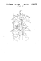
- FIG. 4 is a perspective view of the interspace irrigator of the present invention in place and with the cuff inflated.
- FIG. 4a-4c demonstrates the air bladder mechanism for fitting the cuff.
- FIG. 5 is a perspective view of the interspace irrigator in place and with the secondary occluder in place on the contralateral side.
- FIG. 5a is a side perspective view of the occluder.
- FIG. 6 is a partial perspective view of the mesh trap mechanism.
- FIG. 6a is a side sectional partial sectional view taken along lines 6a--6a of FIG. 4 of the trap.
- FIGS. 6b through 6e show two alternative embodiments of the inflatable cuff.
- FIG. 1 the use of a prior art irrigation bulb B is shown being used to irrigate the disc space D following a partial discectomy.
- FIG. 2 shows that following such an irrigation by conventional prior art means disc fragments F may become lodged beneath the dural sac S, beneath the nerve N, or become trapped in the nerve root canal C, compressing the nerve root N.
- FIG. 3 shows how the use of a dental probe P to search, areas not visible through the access opening for loose disc fragments can result in a further sequestration of the disc fragment F and the rupture of epidural veins V.
- the irrigator consist of syringe S having a plunger 11 with a thumb ring 12. Plunger 11 is able to slide within syringe chamber 13 which is defined by the cylindrical casing 14.
- Two finger rings 15 and 16 may be integrally molded to casing 14 or attached by means of attachment ring 17.
- a mesh trap ring 18 Contained within the lower end of chamber 13 is a mesh trap ring 18 attached by hinge 19 to the inside casing 14.
- the trap ring 18 contains a central mesh area 20 and a solid perimeter 21.
- a long pliant hollow tube 23 made of soft plastic, such as SILASTIC--registered trademark, or an equivalent material is connected to the lower end of chamber 13 by flange 22 the other end of the tube 23 ending with opening 24.
- an inflatable cuff 25 which surrounds the hollow tube 23.
- the inflatable cuff in the preferred embodiment, is merely doughnut shaped, but may also be shaped like a button, mushroom cap, or even be bilobular with a figure eight configuration. This cuff may also be made of foam or gel and be noninflatable.
- the interior of the inflatable cuff 25 is connected by small hollow tube 26 to a small air puffing bladder 27 mounted to the syringe. Referring to FIGS. 4-6 bladder 27 is shown as having an opening 28 at one end with a flap valve 29 which sits against the inner bladder end 30.
- the bladder 27 has an aperture 31 at its other end connecting to tube 26. Tube 26 may be directly connected to the bladder 27.
- the operation of the device is as follows: When the irrigator tube end 24 is inserted into the disc pace D the cuff 25 is in its deflated condition.
- the bladder 27 is then squeezed, causing the air within the bladder to push the flap 29 against the opening 28 thereby forcing all the air within the bladder out opening 31 and down tube 26, thereby inflating cuff 25 and sealing the entrance hole H in the disc space D.
- Gently squeezing the distal end of the bladder while the bladder is refilling prevents the cuff from spontaneously deflating.
- the plunger 11 is then repeatedly pushed and pulled, causing the fluid to enter the disc space, and then be suctioned out of the disc space, along with the disc fragments into the syringe.
- the mesh ring 18 is pivoted away from the opening in the distal end of the chamber allowing debris to enter the chamber 13.
- the perimeter of the ring 21 is caught in the pressure change forcing ring 18 to fully seat against the distal end of the chamber 13 allowing the fluid to pass through the central mesh area 20 of ring 18 but the mesh area 20 prevents the escape of any debris from the holding chamber 13. Irrigation of the residual disc fragments through a closed system assures that such fragments do not then find its way into the spinal canal.
- the cuff 25 is deflated by squeezing the rear of the bladder 27 causing area 30 to push the flap from opening 28 and allowing the bladder to decompress the inflated cuff. Once the inflatable cuff 25 has been deflated irrigation tube 23 may then be withdrawn.
- the length of the chamber 13 of the syringe 5 is approximately 3 inches long, and has a diameter of approximately 5/8 inches.
- the hollow tube 23 is approximately 6 inches long and has an outside diameter of approximately 1/4 inches.
- the outside diameter of the inflatable cuff, when inflated is large enough to completely fill a 1/2 inch diameter access opening.
- these dimensions may vary depending on the application of the invention.
- the entire bladder and cuff mechanism may be replaced by a cuff of foam, gel, or equivalent resilient material.
- the side opposite the irrigator should have the disc space opening 0 occluded with the occluder 32 consisting of a plastic shaft 33 (solid or hollow) and a foam portion 34 which can be placed in the opening 0 to occlude it.
- the length of shaft 33 is sufficient to allow it to protrude from the wound so that an assistant can maintain its position throughout the irrigation process.
- the above described invention may employ a foam portion instead of an inflatable cuff, or any equivalent material that is pliant and can be used to temporarily plug the opening in the disc space.
- a foam portion instead of an inflatable cuff, or any equivalent material that is pliant and can be used to temporarily plug the opening in the disc space.
- a gel bladder or bladder filled with water might be used.
- the present invention includes a plastic rod with a specially formed foam tip as per FIG. 5 which can be used to temporarily occlude any secondary opening into the interspace to be irrigated.
- FIG. 6b a doughnut shaped cuff is shown.
- FIG. 6c a bulb like structure for fitting within the entire disc opening is shown.
- FIG. 6d a conical solid cone shaped cuff is shown.
- FIG. 6e a solid bulb like structure is shown.
Abstract
Description
Claims (14)
Priority Applications (4)
| Application Number | Priority Date | Filing Date | Title |
|---|---|---|---|
| US07/242,871 US4968298A (en) | 1988-09-12 | 1988-09-12 | Interspace irrigator |
| AU43175/89A AU4317589A (en) | 1988-09-12 | 1989-09-12 | Interspace irrigator |
| CA000611052A CA1314453C (en) | 1988-09-12 | 1989-09-12 | Interspace irrigator |
| PCT/US1989/003860 WO1990002574A1 (en) | 1988-09-12 | 1989-09-12 | Interspace irrigator |
Applications Claiming Priority (1)
| Application Number | Priority Date | Filing Date | Title |
|---|---|---|---|
| US07/242,871 US4968298A (en) | 1988-09-12 | 1988-09-12 | Interspace irrigator |
Publications (1)
| Publication Number | Publication Date |
|---|---|
| US4968298A true US4968298A (en) | 1990-11-06 |
Family
ID=22916483
Family Applications (1)
| Application Number | Title | Priority Date | Filing Date |
|---|---|---|---|
| US07/242,871 Expired - Fee Related US4968298A (en) | 1988-09-12 | 1988-09-12 | Interspace irrigator |
Country Status (4)
| Country | Link |
|---|---|
| US (1) | US4968298A (en) |
| AU (1) | AU4317589A (en) |
| CA (1) | CA1314453C (en) |
| WO (1) | WO1990002574A1 (en) |
Cited By (51)
| Publication number | Priority date | Publication date | Assignee | Title |
|---|---|---|---|---|
| US5183463A (en) * | 1989-02-03 | 1993-02-02 | Elie Debbas | Apparatus for locating a breast mass |
| US5192290A (en) * | 1990-08-29 | 1993-03-09 | Applied Medical Resources, Inc. | Embolectomy catheter |
| WO1993011827A1 (en) * | 1989-02-03 | 1993-06-24 | Elie Debbas | Apparatus and method for locating a breast mass |
| US5290257A (en) * | 1992-01-02 | 1994-03-01 | Zhong Being Tang | Method and apparatus for de-airing the heart |
| US5331975A (en) * | 1990-03-02 | 1994-07-26 | Bonutti Peter M | Fluid operated retractors |
| US5354266A (en) * | 1992-07-06 | 1994-10-11 | Catheter Imaging Systems | Method of epidural surgery |
| US5395317A (en) * | 1991-10-30 | 1995-03-07 | Smith & Nephew Dyonics, Inc. | Unilateral biportal percutaneous surgical procedure |
| US5419772A (en) * | 1993-09-29 | 1995-05-30 | Teitz; Bernard R. | Surgical irrigation apparatus for cleaning and sterilizing wounds and surgical areas during surgery |
| US5445645A (en) * | 1989-02-03 | 1995-08-29 | Debbas; Elie | Apparatus for locating a breast mass |
| US5638872A (en) * | 1995-08-22 | 1997-06-17 | National Safety Advisors, Inc. | Siphoning device for use in basting, measuring or immiscible liquid separation |
| US5662674A (en) * | 1989-02-03 | 1997-09-02 | Debbas; Elie | Apparatus for locating a breast mass |
| WO1997038749A1 (en) * | 1996-04-17 | 1997-10-23 | Lasersurge, Inc. | Apparatus for expanding body tissue |
| US5762629A (en) * | 1991-10-30 | 1998-06-09 | Smith & Nephew, Inc. | Oval cannula assembly and method of use |
| USD398986S (en) | 1996-01-16 | 1998-09-29 | Catheter Imaging Systems, Inc. | Handle interface for steerable catheter |
| US5830197A (en) * | 1994-06-14 | 1998-11-03 | Innovation Technologies, Inc. | Wound irrigation device and method |
| US5846221A (en) * | 1996-02-09 | 1998-12-08 | Catheter Imaging Systems, Inc. | Steerable catheter having disposable module and sterilizable handle and method of connecting same |
| US5857996A (en) * | 1992-07-06 | 1999-01-12 | Catheter Imaging Systems | Method of epidermal surgery |
| USD405881S (en) | 1996-01-16 | 1999-02-16 | Catheter Imaging Systems, Inc. | Handle for steerable catheter |
| US6007531A (en) * | 1995-11-21 | 1999-12-28 | Catheter Imaging Systems, Inc. | Steerable catheter having disposable module and sterilizable handle and method of connecting same |
| US6146355A (en) * | 1996-12-30 | 2000-11-14 | Myelotec, Inc. | Steerable catheter |
| US6213974B1 (en) | 1996-12-30 | 2001-04-10 | Visionary Biomedical, Inc. | Steerable catheter having segmented tip and one-piece inlet housing, and method of fabricating same |
| US6277136B1 (en) | 1990-03-02 | 2001-08-21 | General Surgical Innovations, Inc. | Method for developing an anatomic space |
| US6358266B1 (en) | 1990-03-02 | 2002-03-19 | General Surgical Innovations, Inc. | Active cannulas |
| US6468253B1 (en) | 1994-06-14 | 2002-10-22 | Innovation Technologies, Inc. | Wound irrigation device and method |
| US20040083002A1 (en) * | 2001-04-06 | 2004-04-29 | Belef William Martin | Methods for treating spinal discs |
| US6736815B2 (en) | 2001-09-06 | 2004-05-18 | Core Medical, Inc. | Apparatus and methods for treating spinal discs |
| US20040097949A1 (en) * | 1990-03-02 | 2004-05-20 | Bonutti Peter M. | Fluid operated retractors |
| US20050148958A1 (en) * | 1994-06-14 | 2005-07-07 | Rucinski Paul J. | Novel wound irrigation device and method |
| US20050165367A1 (en) * | 2004-01-28 | 2005-07-28 | Higgins Karen D. | Vaginal lubrication device |
| US20080009828A1 (en) * | 2004-04-16 | 2008-01-10 | Kyphon, Inc. | Spinal diagnostic methods and apparatus |
| US20080009793A1 (en) * | 2005-04-21 | 2008-01-10 | Dabbs Clifton R | Foley Catheter Adaptor |
| US20080065151A1 (en) * | 2003-10-17 | 2008-03-13 | Ginn Richard S | Locator and delivery device and method of use |
| US20080215033A1 (en) * | 2004-04-16 | 2008-09-04 | Kyphon, Inc. | Spinal diagnostic methods and apparatus |
| US7753933B2 (en) | 2000-12-14 | 2010-07-13 | Ensure Medical, Inc. | Plug with detachable guidewire element and methods for use |
| US20110172770A1 (en) * | 2000-12-14 | 2011-07-14 | Michelson Gary K | Method for preparing a space in the human spine |
| US8057510B2 (en) | 2000-12-14 | 2011-11-15 | Ensure Medical, Inc. | Plug with collet and apparatus and method for delivering such plugs |
| US8075587B2 (en) | 2000-12-14 | 2011-12-13 | Ensure Medical, Inc. | Apparatus and methods for sealing vascular punctures |
| US8083768B2 (en) | 2000-12-14 | 2011-12-27 | Ensure Medical, Inc. | Vascular plug having composite construction |
| US8088144B2 (en) | 2005-05-04 | 2012-01-03 | Ensure Medical, Inc. | Locator and closure device and method of use |
| US8241259B2 (en) | 1994-06-14 | 2012-08-14 | Innovation Technologies, Inc. | Wound irrigation device and method |
| US8747439B2 (en) | 2000-03-13 | 2014-06-10 | P Tech, Llc | Method of using ultrasonic vibration to secure body tissue with fastening element |
| US8808329B2 (en) | 1998-02-06 | 2014-08-19 | Bonutti Skeletal Innovations Llc | Apparatus and method for securing a portion of a body |
| US8814902B2 (en) | 2000-05-03 | 2014-08-26 | Bonutti Skeletal Innovations Llc | Method of securing body tissue |
| US8828082B2 (en) | 2009-07-09 | 2014-09-09 | R Tree Innovations, Llc | Inter-body implant |
| US8845699B2 (en) | 1999-08-09 | 2014-09-30 | Bonutti Skeletal Innovations Llc | Method of securing tissue |
| US8845687B2 (en) | 1996-08-19 | 2014-09-30 | Bonutti Skeletal Innovations Llc | Anchor for securing a suture |
| US8852229B2 (en) | 2003-10-17 | 2014-10-07 | Cordis Corporation | Locator and closure device and method of use |
| US8926654B2 (en) | 2005-05-04 | 2015-01-06 | Cordis Corporation | Locator and closure device and method of use |
| US9492148B2 (en) | 2000-12-14 | 2016-11-15 | CARDINAL HEALTH SWITZERLAND 515 GmbH | Apparatus and methods for sealing vascular punctures |
| US9770238B2 (en) | 2001-12-03 | 2017-09-26 | P Tech, Llc | Magnetic positioning apparatus |
| EP4159252A3 (en) * | 2017-10-24 | 2023-06-07 | Buffalo Filter LLC | Apparatus for filtering |
Families Citing this family (1)
| Publication number | Priority date | Publication date | Assignee | Title |
|---|---|---|---|---|
| ES2628055T3 (en) | 2007-07-27 | 2017-08-01 | R Tree Innovations, Llc | Intercorporeal Implantation System |
Citations (7)
| Publication number | Priority date | Publication date | Assignee | Title |
|---|---|---|---|---|
| US451179A (en) * | 1891-04-28 | Valved rubber air-bulb | ||
| US3045677A (en) * | 1960-05-03 | 1962-07-24 | American Cystoscope Makers Inc | Inflatable balloon catheter |
| US3046988A (en) * | 1958-12-01 | 1962-07-31 | Davol Rubber Co | Esophageal nasogastric tube |
| US3527203A (en) * | 1967-12-07 | 1970-09-08 | Leland C Gravlee | Apparatus for circulating a fluid within a body cavity |
| US3633586A (en) * | 1970-04-30 | 1972-01-11 | David S Sheridan | Sterile technique tube end closure and syringe adaptor |
| US3707146A (en) * | 1967-03-07 | 1972-12-26 | Prod Res & Chem Corp | Means to inject a plastic into a cavity to produce a replica thereof |
| US4245639A (en) * | 1979-04-30 | 1981-01-20 | C. R. Bard, Inc. | Self-inflating urinary catheter |
-
1988
- 1988-09-12 US US07/242,871 patent/US4968298A/en not_active Expired - Fee Related
-
1989
- 1989-09-12 CA CA000611052A patent/CA1314453C/en not_active Expired - Fee Related
- 1989-09-12 AU AU43175/89A patent/AU4317589A/en not_active Abandoned
- 1989-09-12 WO PCT/US1989/003860 patent/WO1990002574A1/en unknown
Patent Citations (7)
| Publication number | Priority date | Publication date | Assignee | Title |
|---|---|---|---|---|
| US451179A (en) * | 1891-04-28 | Valved rubber air-bulb | ||
| US3046988A (en) * | 1958-12-01 | 1962-07-31 | Davol Rubber Co | Esophageal nasogastric tube |
| US3045677A (en) * | 1960-05-03 | 1962-07-24 | American Cystoscope Makers Inc | Inflatable balloon catheter |
| US3707146A (en) * | 1967-03-07 | 1972-12-26 | Prod Res & Chem Corp | Means to inject a plastic into a cavity to produce a replica thereof |
| US3527203A (en) * | 1967-12-07 | 1970-09-08 | Leland C Gravlee | Apparatus for circulating a fluid within a body cavity |
| US3633586A (en) * | 1970-04-30 | 1972-01-11 | David S Sheridan | Sterile technique tube end closure and syringe adaptor |
| US4245639A (en) * | 1979-04-30 | 1981-01-20 | C. R. Bard, Inc. | Self-inflating urinary catheter |
Cited By (84)
| Publication number | Priority date | Publication date | Assignee | Title |
|---|---|---|---|---|
| US5662674A (en) * | 1989-02-03 | 1997-09-02 | Debbas; Elie | Apparatus for locating a breast mass |
| US5183463A (en) * | 1989-02-03 | 1993-02-02 | Elie Debbas | Apparatus for locating a breast mass |
| WO1993011827A1 (en) * | 1989-02-03 | 1993-06-24 | Elie Debbas | Apparatus and method for locating a breast mass |
| US5445645A (en) * | 1989-02-03 | 1995-08-29 | Debbas; Elie | Apparatus for locating a breast mass |
| US20040097949A1 (en) * | 1990-03-02 | 2004-05-20 | Bonutti Peter M. | Fluid operated retractors |
| US6277136B1 (en) | 1990-03-02 | 2001-08-21 | General Surgical Innovations, Inc. | Method for developing an anatomic space |
| US5331975A (en) * | 1990-03-02 | 1994-07-26 | Bonutti Peter M | Fluid operated retractors |
| US20080103519A1 (en) * | 1990-03-02 | 2008-05-01 | Bonutti Peter M | Active cannulas |
| US7217273B2 (en) | 1990-03-02 | 2007-05-15 | General Surgical Innovations, Inc. | Fluid operated retractors |
| US6358266B1 (en) | 1990-03-02 | 2002-03-19 | General Surgical Innovations, Inc. | Active cannulas |
| US7311719B2 (en) | 1990-03-02 | 2007-12-25 | General Surgical Innovations, Inc. | Active cannulas |
| US5411509A (en) * | 1990-08-29 | 1995-05-02 | Applied Medical Resources Corporation | Embolectomy catheter |
| US5192290A (en) * | 1990-08-29 | 1993-03-09 | Applied Medical Resources, Inc. | Embolectomy catheter |
| US5395317A (en) * | 1991-10-30 | 1995-03-07 | Smith & Nephew Dyonics, Inc. | Unilateral biportal percutaneous surgical procedure |
| US5762629A (en) * | 1991-10-30 | 1998-06-09 | Smith & Nephew, Inc. | Oval cannula assembly and method of use |
| US5370631A (en) * | 1992-01-02 | 1994-12-06 | Zhong; Being-Tang | Method and apparatus for de-airing the heart |
| US5290257A (en) * | 1992-01-02 | 1994-03-01 | Zhong Being Tang | Method and apparatus for de-airing the heart |
| US6470209B2 (en) | 1992-07-06 | 2002-10-22 | Catheter Imaging Systems, Inc. | System for enhancing visibility in the epidural space |
| US5354266A (en) * | 1992-07-06 | 1994-10-11 | Catheter Imaging Systems | Method of epidural surgery |
| US5857996A (en) * | 1992-07-06 | 1999-01-12 | Catheter Imaging Systems | Method of epidermal surgery |
| US5496269A (en) * | 1992-07-06 | 1996-03-05 | Catheter Imaging Systems, Inc. | Method of epidural surgery |
| US6464682B1 (en) | 1992-07-06 | 2002-10-15 | Catheter Imaging Systems, Inc. | Method of epidural surgery |
| US6925323B2 (en) | 1992-07-06 | 2005-08-02 | Phillip Jack Snoke | System for enhancing visibility in the epidural space |
| US6010493A (en) * | 1992-07-06 | 2000-01-04 | Catheter Imaging Systems | Method of epidural surgery |
| US5419772A (en) * | 1993-09-29 | 1995-05-30 | Teitz; Bernard R. | Surgical irrigation apparatus for cleaning and sterilizing wounds and surgical areas during surgery |
| US8021346B2 (en) | 1994-06-14 | 2011-09-20 | Innovation Technologies, Inc. | Wound irrigation device and method |
| US20050148958A1 (en) * | 1994-06-14 | 2005-07-07 | Rucinski Paul J. | Novel wound irrigation device and method |
| US5830197A (en) * | 1994-06-14 | 1998-11-03 | Innovation Technologies, Inc. | Wound irrigation device and method |
| US8241259B2 (en) | 1994-06-14 | 2012-08-14 | Innovation Technologies, Inc. | Wound irrigation device and method |
| US6468253B1 (en) | 1994-06-14 | 2002-10-22 | Innovation Technologies, Inc. | Wound irrigation device and method |
| US5638872A (en) * | 1995-08-22 | 1997-06-17 | National Safety Advisors, Inc. | Siphoning device for use in basting, measuring or immiscible liquid separation |
| US6007531A (en) * | 1995-11-21 | 1999-12-28 | Catheter Imaging Systems, Inc. | Steerable catheter having disposable module and sterilizable handle and method of connecting same |
| US6017322A (en) * | 1995-11-21 | 2000-01-25 | Catheter Imaging Systems, Inc. | Steerable catheter having disposable module and sterilizable handle and method of connecting same |
| US5860953A (en) * | 1995-11-21 | 1999-01-19 | Catheter Imaging Systems, Inc. | Steerable catheter having disposable module and sterilizable handle and method of connecting same |
| USD398986S (en) | 1996-01-16 | 1998-09-29 | Catheter Imaging Systems, Inc. | Handle interface for steerable catheter |
| USD405881S (en) | 1996-01-16 | 1999-02-16 | Catheter Imaging Systems, Inc. | Handle for steerable catheter |
| US5846221A (en) * | 1996-02-09 | 1998-12-08 | Catheter Imaging Systems, Inc. | Steerable catheter having disposable module and sterilizable handle and method of connecting same |
| WO1997038749A1 (en) * | 1996-04-17 | 1997-10-23 | Lasersurge, Inc. | Apparatus for expanding body tissue |
| US8845687B2 (en) | 1996-08-19 | 2014-09-30 | Bonutti Skeletal Innovations Llc | Anchor for securing a suture |
| US6213974B1 (en) | 1996-12-30 | 2001-04-10 | Visionary Biomedical, Inc. | Steerable catheter having segmented tip and one-piece inlet housing, and method of fabricating same |
| US6146355A (en) * | 1996-12-30 | 2000-11-14 | Myelotec, Inc. | Steerable catheter |
| US8808329B2 (en) | 1998-02-06 | 2014-08-19 | Bonutti Skeletal Innovations Llc | Apparatus and method for securing a portion of a body |
| US8845699B2 (en) | 1999-08-09 | 2014-09-30 | Bonutti Skeletal Innovations Llc | Method of securing tissue |
| US8747439B2 (en) | 2000-03-13 | 2014-06-10 | P Tech, Llc | Method of using ultrasonic vibration to secure body tissue with fastening element |
| US8814902B2 (en) | 2000-05-03 | 2014-08-26 | Bonutti Skeletal Innovations Llc | Method of securing body tissue |
| US8377063B2 (en) * | 2000-12-14 | 2013-02-19 | Warsaw Orthopedic, Inc. | Method for preparing a space in the human spine |
| US8409248B2 (en) | 2000-12-14 | 2013-04-02 | Core Medical, Inc. | Plug with detachable guidewire element and methods for use |
| US9655602B2 (en) | 2000-12-14 | 2017-05-23 | CARDINAL HEALTH SWITZERLAND 515 GmbH | Vascular plug having composite construction |
| US9492148B2 (en) | 2000-12-14 | 2016-11-15 | CARDINAL HEALTH SWITZERLAND 515 GmbH | Apparatus and methods for sealing vascular punctures |
| US8888812B2 (en) | 2000-12-14 | 2014-11-18 | Cordis Corporation | Plug with collet and apparatus and methods for delivering such plugs |
| US7753933B2 (en) | 2000-12-14 | 2010-07-13 | Ensure Medical, Inc. | Plug with detachable guidewire element and methods for use |
| US8083768B2 (en) | 2000-12-14 | 2011-12-27 | Ensure Medical, Inc. | Vascular plug having composite construction |
| US8075587B2 (en) | 2000-12-14 | 2011-12-13 | Ensure Medical, Inc. | Apparatus and methods for sealing vascular punctures |
| US8057510B2 (en) | 2000-12-14 | 2011-11-15 | Ensure Medical, Inc. | Plug with collet and apparatus and method for delivering such plugs |
| US20110172770A1 (en) * | 2000-12-14 | 2011-07-14 | Michelson Gary K | Method for preparing a space in the human spine |
| US20040083002A1 (en) * | 2001-04-06 | 2004-04-29 | Belef William Martin | Methods for treating spinal discs |
| US6736815B2 (en) | 2001-09-06 | 2004-05-18 | Core Medical, Inc. | Apparatus and methods for treating spinal discs |
| US20040158248A1 (en) * | 2001-09-06 | 2004-08-12 | Ginn Richard S. | Apparatus and methods for treating spinal discs |
| US20040172132A1 (en) * | 2001-09-06 | 2004-09-02 | Ginn Richard S. | Apparatus and methods for treating spinal discs |
| US9770238B2 (en) | 2001-12-03 | 2017-09-26 | P Tech, Llc | Magnetic positioning apparatus |
| US20080065151A1 (en) * | 2003-10-17 | 2008-03-13 | Ginn Richard S | Locator and delivery device and method of use |
| US8852229B2 (en) | 2003-10-17 | 2014-10-07 | Cordis Corporation | Locator and closure device and method of use |
| US8579934B2 (en) | 2003-10-17 | 2013-11-12 | Ensure Medical, Inc. | Locator and delivery device and method of use |
| US20050165367A1 (en) * | 2004-01-28 | 2005-07-28 | Higgins Karen D. | Vaginal lubrication device |
| US7452351B2 (en) | 2004-04-16 | 2008-11-18 | Kyphon Sarl | Spinal diagnostic methods and apparatus |
| US20080215033A1 (en) * | 2004-04-16 | 2008-09-04 | Kyphon, Inc. | Spinal diagnostic methods and apparatus |
| US20080009826A1 (en) * | 2004-04-16 | 2008-01-10 | Kyphon, Inc. | Spinal diagnostic methods and apparatus |
| US8157786B2 (en) * | 2004-04-16 | 2012-04-17 | Kyphon Sarl | Spinal diagnostic methods and apparatus |
| US20080009828A1 (en) * | 2004-04-16 | 2008-01-10 | Kyphon, Inc. | Spinal diagnostic methods and apparatus |
| US7955312B2 (en) * | 2004-04-16 | 2011-06-07 | Kyphon Sarl | Spinal diagnostic methods and apparatus |
| US20090054935A1 (en) * | 2004-04-16 | 2009-02-26 | Kyphon Sarl | Spinal Diagnostic Methods and Apparatus |
| US7824390B2 (en) | 2004-04-16 | 2010-11-02 | Kyphon SÀRL | Spinal diagnostic methods and apparatus |
| US7905874B2 (en) * | 2004-04-16 | 2011-03-15 | Kyphon Sarl | Spinal diagnostic methods and apparatus |
| US7766870B2 (en) * | 2005-04-21 | 2010-08-03 | The United States Of America As Represented By The Secretary Of The Army | Foley catheter adaptor |
| US20080009793A1 (en) * | 2005-04-21 | 2008-01-10 | Dabbs Clifton R | Foley Catheter Adaptor |
| US8926654B2 (en) | 2005-05-04 | 2015-01-06 | Cordis Corporation | Locator and closure device and method of use |
| US9289198B2 (en) | 2005-05-04 | 2016-03-22 | Cordis Corporation | Locator and closure device and method of use |
| US8088144B2 (en) | 2005-05-04 | 2012-01-03 | Ensure Medical, Inc. | Locator and closure device and method of use |
| US8828082B2 (en) | 2009-07-09 | 2014-09-09 | R Tree Innovations, Llc | Inter-body implant |
| US9814599B2 (en) | 2009-07-09 | 2017-11-14 | R Tree Innovations, Llc | Inter-body implantation system and method |
| US9877844B2 (en) | 2009-07-09 | 2018-01-30 | R Tree Innovations, Llc | Inter-body implant |
| US10806594B2 (en) | 2009-07-09 | 2020-10-20 | R Tree Innovations, Llc | Inter-body implant |
| US10835386B2 (en) | 2009-07-09 | 2020-11-17 | R Tree Innovations, Llc | Inter-body implantation system and method |
| EP4159252A3 (en) * | 2017-10-24 | 2023-06-07 | Buffalo Filter LLC | Apparatus for filtering |
Also Published As
| Publication number | Publication date |
|---|---|
| WO1990002574A1 (en) | 1990-03-22 |
| AU4317589A (en) | 1990-04-02 |
| CA1314453C (en) | 1993-03-16 |
Similar Documents
| Publication | Publication Date | Title |
|---|---|---|
| US4968298A (en) | Interspace irrigator | |
| US5649902A (en) | Multifunctional devices for endoscopic surgical procedures | |
| US5192290A (en) | Embolectomy catheter | |
| JP2716588B2 (en) | Endoscope portal used under endoscope and method therefor | |
| US5279548A (en) | Peritoneal surgical method | |
| US6048331A (en) | Cardioplegia occluder | |
| US6027478A (en) | Nasal cavity drainage and stoppage system | |
| US5645083A (en) | Peritoneal surgical method | |
| US7641669B2 (en) | Intravascular occlusion balloon catheter | |
| JP4282242B2 (en) | Specially shaped balloon device for use in surgery and method of use thereof | |
| JP2528602B2 (en) | Plug device for sealing the opening | |
| US6152932A (en) | Device for extraction of tissue | |
| US6371968B1 (en) | Cavity retaining tool for bone surgery, a cavity retaining tool for general surgery, an endoscopic surgery system involving the use of a cavity retaining tool, and a procedure for surgery | |
| US4681110A (en) | Catheter arrangement having a blood vessel liner, and method of using it | |
| US5102415A (en) | Apparatus for removing blood clots from arteries and veins | |
| US5695519A (en) | Percutaneous filter for carotid angioplasty | |
| US5275616A (en) | Insertion assembly and method of inserting a vessel plug into the body of a patient | |
| AU583989B2 (en) | Ophthalmic aspirating/irrigating device | |
| CN113974766A (en) | Thrombus-taking catheter | |
| CA2427628C (en) | Catheter for removal of solids from surgical drains | |
| US20040199202A1 (en) | Biological passageway occlusion removal | |
| US20080009875A1 (en) | Medical device with dual expansion mechanism | |
| BRPI0609542A2 (en) | instrument for inserting a hydrogel prosthesis into an intervertebral disc, instrument kit for inserting an elongated hydrogel prosthesis into an intervertebral disc, and instrument for determining the volume within an intervertebral disc | |
| CA2190976A1 (en) | Expandable multi-functional manipulating instruments | |
| EP1663368B1 (en) | Embolic protection aspirator |
Legal Events
| Date | Code | Title | Description |
|---|---|---|---|
| FPAY | Fee payment |
Year of fee payment: 4 |
|
| FEPP | Fee payment procedure |
Free format text: PAT HOLDER CLAIMS SMALL ENTITY STATUS - SMALL BUSINESS (ORIGINAL EVENT CODE: SM02); ENTITY STATUS OF PATENT OWNER: SMALL ENTITY Free format text: PAT HLDR NO LONGER CLAIMS SMALL ENT STAT AS INDIV INVENTOR (ORIGINAL EVENT CODE: LSM1); ENTITY STATUS OF PATENT OWNER: SMALL ENTITY |
|
| FPAY | Fee payment |
Year of fee payment: 8 |
|
| FEPP | Fee payment procedure |
Free format text: PAYOR NUMBER ASSIGNED (ORIGINAL EVENT CODE: ASPN); ENTITY STATUS OF PATENT OWNER: SMALL ENTITY |
|
| REMI | Maintenance fee reminder mailed | ||
| LAPS | Lapse for failure to pay maintenance fees | ||
| STCH | Information on status: patent discontinuation |
Free format text: PATENT EXPIRED DUE TO NONPAYMENT OF MAINTENANCE FEES UNDER 37 CFR 1.362 |
|
| FP | Lapsed due to failure to pay maintenance fee |
Effective date: 20021106 |
|
| AS | Assignment |
Owner name: SDGI HOLDINGS, INC.,DELAWARE Free format text: ASSIGNMENT OF ASSIGNORS INTEREST;ASSIGNORS:MICHELSON, GARY KARLIN;KARLIN TECHNOLOGY, INC.;REEL/FRAME:016195/0282 Effective date: 20050517 Owner name: SDGI HOLDINGS, INC., DELAWARE Free format text: ASSIGNMENT OF ASSIGNORS INTEREST;ASSIGNORS:MICHELSON, GARY KARLIN;KARLIN TECHNOLOGY, INC.;REEL/FRAME:016195/0282 Effective date: 20050517 |
|
| AS | Assignment |
Owner name: WARSAW ORTHOPEDIC, INC., INDIANA Free format text: MERGER;ASSIGNOR:SDGI HOLDINGS, INC.;REEL/FRAME:018797/0655 Effective date: 20060428 |