US4977487A - Face brightening device for use with vehicles - Google Patents
Face brightening device for use with vehicles Download PDFInfo
- Publication number
- US4977487A US4977487A US07/254,819 US25481988A US4977487A US 4977487 A US4977487 A US 4977487A US 25481988 A US25481988 A US 25481988A US 4977487 A US4977487 A US 4977487A
- Authority
- US
- United States
- Prior art keywords
- brightening device
- optical fibers
- face
- face brightening
- notched
- Prior art date
- Legal status (The legal status is an assumption and is not a legal conclusion. Google has not performed a legal analysis and makes no representation as to the accuracy of the status listed.)
- Expired - Lifetime
Links
Images


Classifications
-
- G—PHYSICS
- G02—OPTICS
- G02B—OPTICAL ELEMENTS, SYSTEMS OR APPARATUS
- G02B6/00—Light guides; Structural details of arrangements comprising light guides and other optical elements, e.g. couplings
- G02B6/0001—Light guides; Structural details of arrangements comprising light guides and other optical elements, e.g. couplings specially adapted for lighting devices or systems
- G02B6/0005—Light guides; Structural details of arrangements comprising light guides and other optical elements, e.g. couplings specially adapted for lighting devices or systems the light guides being of the fibre type
- G02B6/001—Light guides; Structural details of arrangements comprising light guides and other optical elements, e.g. couplings specially adapted for lighting devices or systems the light guides being of the fibre type the light being emitted along at least a portion of the lateral surface of the fibre
-
- B—PERFORMING OPERATIONS; TRANSPORTING
- B60—VEHICLES IN GENERAL
- B60Q—ARRANGEMENT OF SIGNALLING OR LIGHTING DEVICES, THE MOUNTING OR SUPPORTING THEREOF OR CIRCUITS THEREFOR, FOR VEHICLES IN GENERAL
- B60Q1/00—Arrangement of optical signalling or lighting devices, the mounting or supporting thereof or circuits therefor
- B60Q1/26—Arrangement of optical signalling or lighting devices, the mounting or supporting thereof or circuits therefor the devices being primarily intended to indicate the vehicle, or parts thereof, or to give signals, to other traffic
- B60Q1/2661—Arrangement of optical signalling or lighting devices, the mounting or supporting thereof or circuits therefor the devices being primarily intended to indicate the vehicle, or parts thereof, or to give signals, to other traffic mounted on parts having other functions
-
- B—PERFORMING OPERATIONS; TRANSPORTING
- B60—VEHICLES IN GENERAL
- B60Q—ARRANGEMENT OF SIGNALLING OR LIGHTING DEVICES, THE MOUNTING OR SUPPORTING THEREOF OR CIRCUITS THEREFOR, FOR VEHICLES IN GENERAL
- B60Q1/00—Arrangement of optical signalling or lighting devices, the mounting or supporting thereof or circuits therefor
- B60Q1/26—Arrangement of optical signalling or lighting devices, the mounting or supporting thereof or circuits therefor the devices being primarily intended to indicate the vehicle, or parts thereof, or to give signals, to other traffic
- B60Q1/50—Arrangement of optical signalling or lighting devices, the mounting or supporting thereof or circuits therefor the devices being primarily intended to indicate the vehicle, or parts thereof, or to give signals, to other traffic for indicating other intentions or conditions, e.g. request for waiting or overtaking
- B60Q1/503—Arrangement of optical signalling or lighting devices, the mounting or supporting thereof or circuits therefor the devices being primarily intended to indicate the vehicle, or parts thereof, or to give signals, to other traffic for indicating other intentions or conditions, e.g. request for waiting or overtaking using luminous text or symbol displays in or on the vehicle, e.g. static text
-
- B—PERFORMING OPERATIONS; TRANSPORTING
- B60—VEHICLES IN GENERAL
- B60Q—ARRANGEMENT OF SIGNALLING OR LIGHTING DEVICES, THE MOUNTING OR SUPPORTING THEREOF OR CIRCUITS THEREFOR, FOR VEHICLES IN GENERAL
- B60Q3/00—Arrangement of lighting devices for vehicle interiors; Lighting devices specially adapted for vehicle interiors
- B60Q3/10—Arrangement of lighting devices for vehicle interiors; Lighting devices specially adapted for vehicle interiors for dashboards
- B60Q3/14—Arrangement of lighting devices for vehicle interiors; Lighting devices specially adapted for vehicle interiors for dashboards lighting through the surface to be illuminated
-
- B—PERFORMING OPERATIONS; TRANSPORTING
- B60—VEHICLES IN GENERAL
- B60Q—ARRANGEMENT OF SIGNALLING OR LIGHTING DEVICES, THE MOUNTING OR SUPPORTING THEREOF OR CIRCUITS THEREFOR, FOR VEHICLES IN GENERAL
- B60Q3/00—Arrangement of lighting devices for vehicle interiors; Lighting devices specially adapted for vehicle interiors
- B60Q3/60—Arrangement of lighting devices for vehicle interiors; Lighting devices specially adapted for vehicle interiors characterised by optical aspects
- B60Q3/62—Arrangement of lighting devices for vehicle interiors; Lighting devices specially adapted for vehicle interiors characterised by optical aspects using light guides
- B60Q3/64—Arrangement of lighting devices for vehicle interiors; Lighting devices specially adapted for vehicle interiors characterised by optical aspects using light guides for a single lighting device
-
- F—MECHANICAL ENGINEERING; LIGHTING; HEATING; WEAPONS; BLASTING
- F21—LIGHTING
- F21S—NON-PORTABLE LIGHTING DEVICES; SYSTEMS THEREOF; VEHICLE LIGHTING DEVICES SPECIALLY ADAPTED FOR VEHICLE EXTERIORS
- F21S43/00—Signalling devices specially adapted for vehicle exteriors, e.g. brake lamps, direction indicator lights or reversing lights
- F21S43/20—Signalling devices specially adapted for vehicle exteriors, e.g. brake lamps, direction indicator lights or reversing lights characterised by refractors, transparent cover plates, light guides or filters
- F21S43/235—Light guides
- F21S43/236—Light guides characterised by the shape of the light guide
- F21S43/237—Light guides characterised by the shape of the light guide rod-shaped
-
- F—MECHANICAL ENGINEERING; LIGHTING; HEATING; WEAPONS; BLASTING
- F21—LIGHTING
- F21S—NON-PORTABLE LIGHTING DEVICES; SYSTEMS THEREOF; VEHICLE LIGHTING DEVICES SPECIALLY ADAPTED FOR VEHICLE EXTERIORS
- F21S43/00—Signalling devices specially adapted for vehicle exteriors, e.g. brake lamps, direction indicator lights or reversing lights
- F21S43/20—Signalling devices specially adapted for vehicle exteriors, e.g. brake lamps, direction indicator lights or reversing lights characterised by refractors, transparent cover plates, light guides or filters
- F21S43/235—Light guides
- F21S43/242—Light guides characterised by the emission area
- F21S43/245—Light guides characterised by the emission area emitting light from one or more of its major surfaces
-
- F—MECHANICAL ENGINEERING; LIGHTING; HEATING; WEAPONS; BLASTING
- F21—LIGHTING
- F21S—NON-PORTABLE LIGHTING DEVICES; SYSTEMS THEREOF; VEHICLE LIGHTING DEVICES SPECIALLY ADAPTED FOR VEHICLE EXTERIORS
- F21S43/00—Signalling devices specially adapted for vehicle exteriors, e.g. brake lamps, direction indicator lights or reversing lights
- F21S43/20—Signalling devices specially adapted for vehicle exteriors, e.g. brake lamps, direction indicator lights or reversing lights characterised by refractors, transparent cover plates, light guides or filters
- F21S43/235—Light guides
- F21S43/247—Light guides with a single light source being coupled into the light guide
-
- F—MECHANICAL ENGINEERING; LIGHTING; HEATING; WEAPONS; BLASTING
- F21—LIGHTING
- F21S—NON-PORTABLE LIGHTING DEVICES; SYSTEMS THEREOF; VEHICLE LIGHTING DEVICES SPECIALLY ADAPTED FOR VEHICLE EXTERIORS
- F21S43/00—Signalling devices specially adapted for vehicle exteriors, e.g. brake lamps, direction indicator lights or reversing lights
- F21S43/20—Signalling devices specially adapted for vehicle exteriors, e.g. brake lamps, direction indicator lights or reversing lights characterised by refractors, transparent cover plates, light guides or filters
- F21S43/235—Light guides
- F21S43/251—Light guides the light guides being used to transmit light from remote light sources
-
- G—PHYSICS
- G09—EDUCATION; CRYPTOGRAPHY; DISPLAY; ADVERTISING; SEALS
- G09F—DISPLAYING; ADVERTISING; SIGNS; LABELS OR NAME-PLATES; SEALS
- G09F13/00—Illuminated signs; Luminous advertising
- G09F13/04—Signs, boards or panels, illuminated from behind the insignia
- G09F13/0418—Constructional details
- G09F13/0472—Traffic signs
-
- G—PHYSICS
- G09—EDUCATION; CRYPTOGRAPHY; DISPLAY; ADVERTISING; SEALS
- G09F—DISPLAYING; ADVERTISING; SIGNS; LABELS OR NAME-PLATES; SEALS
- G09F9/00—Indicating arrangements for variable information in which the information is built-up on a support by selection or combination of individual elements
- G09F9/30—Indicating arrangements for variable information in which the information is built-up on a support by selection or combination of individual elements in which the desired character or characters are formed by combining individual elements
- G09F9/305—Indicating arrangements for variable information in which the information is built-up on a support by selection or combination of individual elements in which the desired character or characters are formed by combining individual elements being the ends of optical fibres
-
- B—PERFORMING OPERATIONS; TRANSPORTING
- B60—VEHICLES IN GENERAL
- B60Q—ARRANGEMENT OF SIGNALLING OR LIGHTING DEVICES, THE MOUNTING OR SUPPORTING THEREOF OR CIRCUITS THEREFOR, FOR VEHICLES IN GENERAL
- B60Q1/00—Arrangement of optical signalling or lighting devices, the mounting or supporting thereof or circuits therefor
- B60Q1/26—Arrangement of optical signalling or lighting devices, the mounting or supporting thereof or circuits therefor the devices being primarily intended to indicate the vehicle, or parts thereof, or to give signals, to other traffic
- B60Q1/50—Arrangement of optical signalling or lighting devices, the mounting or supporting thereof or circuits therefor the devices being primarily intended to indicate the vehicle, or parts thereof, or to give signals, to other traffic for indicating other intentions or conditions, e.g. request for waiting or overtaking
- B60Q1/52—Arrangement of optical signalling or lighting devices, the mounting or supporting thereof or circuits therefor the devices being primarily intended to indicate the vehicle, or parts thereof, or to give signals, to other traffic for indicating other intentions or conditions, e.g. request for waiting or overtaking for indicating emergencies
-
- G—PHYSICS
- G09—EDUCATION; CRYPTOGRAPHY; DISPLAY; ADVERTISING; SEALS
- G09F—DISPLAYING; ADVERTISING; SIGNS; LABELS OR NAME-PLATES; SEALS
- G09F13/00—Illuminated signs; Luminous advertising
- G09F13/20—Illuminated signs; Luminous advertising with luminescent surfaces or parts
- G09F13/22—Illuminated signs; Luminous advertising with luminescent surfaces or parts electroluminescent
-
- Y—GENERAL TAGGING OF NEW TECHNOLOGICAL DEVELOPMENTS; GENERAL TAGGING OF CROSS-SECTIONAL TECHNOLOGIES SPANNING OVER SEVERAL SECTIONS OF THE IPC; TECHNICAL SUBJECTS COVERED BY FORMER USPC CROSS-REFERENCE ART COLLECTIONS [XRACs] AND DIGESTS
- Y10—TECHNICAL SUBJECTS COVERED BY FORMER USPC
- Y10S—TECHNICAL SUBJECTS COVERED BY FORMER USPC CROSS-REFERENCE ART COLLECTIONS [XRACs] AND DIGESTS
- Y10S362/00—Illumination
- Y10S362/812—Signs
Definitions
- Head lamps, tail lamps, emblem and the like form brightening faces outside the vehicle while meters in front of the driver's seat are brightened inside the vehicle.
- Rear combination lamps (f) and (f') of a car (C 2 ) shown in FIG. 2a are relatively too large in thickness (t 2 ) and the space in which the rear combination lamps are housed is also quite large in thickness (t 3 ) relative to the size of the car body.
- Each of the rear combination lamps (f) and (f') which must be brought under legal rules and brightened as decorations is made as a unit comprising a brake lamp (m 1 ), tail lamp (m 2 ), traffic indicator or blinker (m 3 ) and emergency lamp (m 4 ), as shown in FIG. 2b, and these components take up a large space, thereby reducing the size of trunk room at the back of the car.
- FIG. 2c is a sectional view showing the rear combination lamp (f) or (f') in FIG. 2b and when the lamp becomes complicated in construction, its thickness (t 4 ) ranges even from 100 mm to 180 mm because a filament bulb (w) attached to a lamp body (D) must have a certain distance relative to a lens (R) to uniformly brighten the lens (R). Even when the lamp is designed like this, however, the lens (R) cannot be brightened as a uniformly light-emitting face.
- the inside space (s) of the rear combination lamp (f) or (f') must be sealed in view of electric insulation.
- the conventional front grille was made by sputtering, plating, or coating opaque synthetic resin with a design.
- the front grille (F) plays the most important role in designing a car (C 3 ) and it is desirable that the front grille is made integral to the body of the car. It is also desirable in view of aerodynamic design that the front grille be made integral with the headlights. Because the recent car body is made flush and provided with glass faces, a transparent crystal front grille is employed.
- the design merit of making the front grille of transparent material is only three-dimensional and too simple, as compared with the design merit of making the front grille by sputtering, plating or coating opaque synthetic resin.
- the front grille looks gloomy particularly at the twilight and in the night because it has no metal surface which reflects light.
- FIGS. 4a and 4b show an indicator (Y 1 ) for the transmission change gear lever in the conventional automatic car wherein a filament bulb (w) is fixed to an indicator body (Y 2 ) to light the underside of a display housing (H) so that letters P, R, N, D, 2 and L on a display (B) can be lit with same brightness and color tone.
- Symbol (S) represents a slider sliding in the longitudinal direction thereof and the change gear lever (not shown) is passed through a hole (g) in the center of the slider (S) and a slit (g') in the display housing (H).
- the transmission change gear lever is switched, one of the letters (b) is brightened red through a transparent mark (M), showing the position of the transmission change gear lever.
- the position of the change gear lever in the automatic car is usually displayed by the letters of P, R, N, D, 2 and L, and P, R, D, 2 and L of them are white in tone while N is green in tone. These letters are made so bright that the driver can see them, particularly in the night, and they must have the same brightness and color tone.
- the present invention relates to a face-brightening device for use inside and outside the vehicles.
- the face-brightening device comprises optical fibers wherein the optical fibers are notched at their intended portions and a light source is attached to their one or both ends to brighten their intended notched portions.
- An object of the present invention is to provide a face-brightening device comprising optical fibers wherein light introduced from a light source into the optical fibers is emitted through notched portions of the optical fibers to emerge as letters, patterns or the like, whereby light brightening faces are excellent in water-proofness, heat-resistance, weather-proofness and insulation can be formed with lighter weight and smaller space inside and outside the vehicles.
- Another object of the present invention is to provide illuminating lamps such as the rear combination lamp which can have uniformly brightening faces and which can be safely used in a smaller space.
- a still further object of the present invention is to provide a front grille and a rear panel for use with vehicles which can be excellent in design and which can be beautifully brightened, particularly in the night.
- a still further object of the present invention is to provide an indicator for the transmission change gear lever in vehicles capable of uniformly brightening letters on the display of the display housing by means of optical fibers.
- FIG. 1 is a perspective view showing the display section at the back of the conventional vehicle dismantled.
- FIG. 2a is a perspective view showing the display section at the back of the conventional vehicle.
- FIG. 2b is a perspective view showing the conventional rear combination lamp.
- FIG. 2c is a sectional view taken along a line 2c 2c' in FIG. 2b.
- FIG. 4a is a perspective view showing an indicator for the change gear lever in the conventional automatic car.
- FIG. 4a shows the indicator dismantled.
- FIG. 5a is a perspective view showing an optical fiber enlarged.
- FIG. 5b is an enlarged sectional view taken along a line 5b-5b' in FIG. 5a .
- FIG. 6a is a front view showing a face brightening device of the present invention.
- FIG. 6b is a sectional view taken along a line 6b -6b' in FIG. 6a.
- FIG. 6c is a sectional view taken along a line 6c -6c' in FIG. 6a.
- FIG. 6d is a perspective view showing another example of the face brightening device according to the present invention.
- FIG. 6e is an enlarged sectional view taken along a line 6e-6e' in FIG. 6d.
- FIG. 6f is a perspective view showing a further example of the face brightening device according to the present invention.
- FIG. 6g is a perspective view showing a still further example of the face brightening device according to the present invention.
- FIG. 6h is a front view showing a still further example of the face brightening device according to the present invention.
- FIG. 7a shows how the optical fiber is notched.
- FIG. 7b shows a part of the optical fiber enlarged.
- FIG. 8a is a perspective view showing the face brightening device of the present invention used as a rear panel of the car.
- FIG. 9 is a sectional view showing a light source attached to one ends of optical fibers.
- FIG. 10 shows to which parts of the car the face brightening device of the present invention is applied.
- FIG. 11a is a perspective view showing a rear combination lamp to which the present invention is applied and which is dismantled.
- FIG. 11b is a perspective view showing how the rear combination lamp to which the present invention is applied is assembled.
- FIG. 11c is an enlarged sectional view taken along a line 11c-11c' in FIG. 11b.
- FIG. 11d shows a part of the rear combination lamp in FIG. 11c enlarged.
- FIG. 12 is a sectional view showing another light source connected to the optical fibers.
- FIG. 13 is a perspective view showing a still further example of the face brightening device according to the present invention.
- FIG. 14 shows a hood ornament of the car.
- FIG. 15a is a front view showing a hood ornament to which the face brightening device of the present invention is applied.
- FIG. 15b is a sectional view taken along a line 15b-15b' in FIG. 15a.
- FIG. 16 is a front view showing the face brightening device of the present invention used as the hood ornament.
- FIG. 17 is an enlarged sectional view taken along a line 17-17' in FIG. 16.
- FIG. 18 is an enlarged sectional view, similar to FIG. 17, showing a variation of the hood ornament.
- FIG. 19b is a sectional view taken along a line 19b-19b' in FIG. 19a.
- FIG. 20a is a perspective view showing the backside of another front grille to which the face brightening device of the present invention is applied.
- FIG. 20b is a sectional view taken along a line 20b-20b' in FIG. 20a.
- FIG. 21a is a front view showing a rear panel to which the face brightening device of the present invention is applied.
- FIG. 21b is a perspective view showing the backside of the rear panel enlarged.
- FIG. 21c is an enlarged sectional view taken along a line 21c-21c' in FIG. 21a.
- FIG. 22a is a plan showing an indicator for the transmission change gear lever to which the face brightening device of the present invention is applied.
- FIG. 22b is a sectional view taken along a line 22b-22b'0 in FIG. 22a .
- FIG. 23 is a perspective view showing the face brightening device of the present invention used as the indicator for the transmission change gear lever.
- FIG. 24a is a perspective view showing the backside of a display housing for the indicator.
- FIG. 24b is a sectional view showing the indicator for the change gear lever.
- an optical fiber 1 having a diameter of 0.1-3.0 ⁇ is usually used but its diameter may be larger according to its brightness which it is expected to be achieved and also according to its arrangement when it is used to assemble a face brightening device.
- a light source for the optical fibers 1 is located at a position different from those of the filament bulbs for the rear combination lamps (f) and (f') and light emitted from the light source is introduced into the optical fibers 1 through another optical fiber or the like.
- the optical fiber 1 is made by coating a synthetic resin of the fluorine group around layers of a transparent synthetic resin so as to reduce light leakage as much as possible.
- the optical fiber 1 has a portion to be brightened and another portion extending to the light source.
- the portion of the optical fiber 1 which is to be brightened is notched at the backside thereof, as shown in FIG. 5c.
- a fluorescent paint 5' is coated on this notched portion of the optical fiber 1, the brightness of its notched portion can be made high.
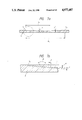
- FIG. 6a shows a face brightening device (A) comprising the optical fibers 1 wherein a plurality of the optical fibers 1 are fixed side by side on a base film 2 made of synthetic resin to form a brightening section 3.
- the thickness of this brightening section 3 ranges from 0.l mm to 1.5 mm.
- the optical fibers 1 are notched at their brightening section 3 to draw letters (b) by their notched portions 5.
- Light sources (L) and (L') are arranged to 0 face terminals 6 and 6', respectively, which bundle both ends of the optical fibers 1.
- FIG. 6b is a sectional view taken along a line 6b-6b' in FIG. 6a and FIG. 6c is also a sectional view taken along a line 6c-6c' in FIG. 6a, which show that the optical fibers 1 are positioned on the base film 2 and that those portions 5 of the optical fibers 1 which represent the letters (b) are notched. Those backsides of the optical fibers 1 which correspond to the notched portions 5 may be notched instead of the notched portions 5, as shown in FIG. 5c.
- the optical fibers 1 are arranged side by side and fixed together to form a flat portion 10.
- the optical fibers 1 are bundled at both ends of the flat portion 10 to form two bundles 4 and 4' of the optical fibers 1, which are connected to a coupler 6a.
- Those portions of the optical fibers 1 which are to be brightened are notched at the backside of the flat portion 10 to form notched portions 5.
- FIG. 6e shows the section of the flat portion 10 in FIG. 6d and when the notched portions 5 are coated with a fluorescent paint 5', their brightness can be enhanced.
- FIG. 6f shows a face brightening device (A) provided with a coupler 6a only at one end thereof.
- FIG. 6g shows a variation of the face brightening device wherein the optical fibers 1 are arranged side by side and fixed together to form a flat portion 10 having an area (n 1 by n 3 ) enough to correspond to a brightening portion (n 1 by n 2 ) and a margin needed to attach the face brightening device to a certain place.
- FIG. 6h shows another variation of the face brightening device wherein two couplers 6a and 6a' are connected to both ends of bundled optical fibers 1, respectively.
- a notched portion 5 is formed on the front or back side of the flat portion 10, corresponding to the brightening portion (n 1 by n 2 ) in FIGS. 6g and 6h.
- the flat portion 10 including the area (n 1 by n 2 ) to be brightened in FIG. 6g is tilted by angles ⁇ and ⁇ ' along a center line extending in the longitudinal direction of the area (n 1 by n 2 ) and between an outermost point (V 1 ) of the area and another outermost point (V 2 ) of the margin and recesses (r) each having a certain depth are formed on the optical fibers 1 at the area (n 1 by n 2 ), adjusting their angle ⁇ and pitch (p).
- This manner of notching the optical fibers 1 is carried out in such a way that a press on which the recesses (r) are formed with such shape, angle ⁇ and depth as meet the brightness of the area to be brightened is pushed against the optical fibers 1 with heat and pressure.
- FIG. 8a shows the face brightening device used as a rear panel garnish (a) of the car wherein a layer of opaque ink 7 covers the optical fibers 1 except the notched portions thereof which represent the letters (b) and a transparent panel 8 is placed thereon, as shown in FIG. 8b.
- the notched portions 5 on the optical fibers 1 may be formed on those backsides of the optical fibers 1 which correspond to the letters (b).
- Letters, patterns or the like can be brightened at the brightening face and when the brightening face is notched all over it, it can be brightened as a face.
- Light can be introduced from the light source for the head lamps, rear back lamps or the like into the optical fibers 1 through the bundled portion of the optical fibers, as described above.
- a light emitting box (LB) may be used as the light source, as shown in FIG. 9 and when a color filter 9 is arranged between a light source (L) and the bundled portion 4 of the optical fibers 1, the color of light can be freely selected.
- FIG. 10 shows to which parts of a car (C 4 ) the face brightening device of the present invention can be applied, except the rear panel garnish (a).
- the face brightening device is applied to the quarter window garnish (h), center pillar garnish (j), side protector mold (k), step plate, bumper mold, inside of the trunk room and the like, letters, patterns or the like can be brightened at these parts.
- FIG. 11a shows face brightening devices (A), (A 1 ) and (A 2 ) combined with one another to form a rear combination lamp (f) or (f').
- the face brightening device (A) is fixed to a reflector plate 12 along the curved front face thereof which has such a shape as can be along the front face of a lamp body 11 and which is made, 0.5 mm thick, by vacuum-molding white synthetic resin, and the face brightening devices (A 1 ) and (A 2 ) are further fixed to the face brightening device (A).
- These reflector plate and face brightening devices may be fixed to one another by means of transparent adhesive or transparent two sided adhesive tape.
- the face brightening devices (A), (A 1 ) and (A 2 ) thus assembled with the reflector plate 12 are fixed to the lamp body 11 and couplers 6a and 6a' for connecting the face brightening devices to their light sources are extended outside the lamp body through coupler holes.
- a transparent colored lens 13 is then attached to the lamp body 11 to form the rear combination lamp (f) or (f').
- the transparent colored lens 13 in FIG. 11a comprises a red lens 13a and an orange-colored lens 13b.
- a tail lamp (m 1 ) is turned on.
- a brake lamp (m 2 ) is lit.
- a traffic indicator or blinker (m 3 ) is turned on.
- an emergency lamp (m 4 ) flashes.
- FIG. 11b shows the rear combination lamp (f) or (f') assembled as described above
- FIG. 11c is a sectional view taken along a line 11c-11c' in FIG. 11b
- FIG. 11d shows on an enlarged scale a part of the lamp enclosed by a two-dot and dash line in FIG. 11c.
- the face brightening device (A) fixed to the front face of the reflector plate 12 is placed on the front face of the lamp body 11 and the face brightening device (A 1 ) is further placed on the front face of the face brightening device (A).
- the optical fibers in the one face brightening device When the optical fibers in the one face brightening device are arranged side by side in the vertical direction in the case where the notched flat portions of the optical fibers in both face brightening devices (A) and (A 1 ) are brightened, the optical fibers in the other face brightening device may be arranged side by side in the traverse direction.
- FIG. 12 shows an example of the light emitting box (LB) wherein light emitted from a halogen lamp (w') is reflected toward a coupler 6a by a reflector plate 12'.
- the depth of the recesses (r) on the flat portion of the optical fibers in the face brightening device (A) is made large at a zone (a 1 ) in FIG. 13 which must be strongly brightened as the brake lamp and their angle ⁇ is also adjusted accordingly. Their depth, however, is made small at a zone (a 2 ) which may be less strongly brightened as the lamp for showing the car width and their angle ⁇ is adjusted accordingly.
- a zone (a 3 ) is brightened as the back lamp.
- the brightness of the lamps can be adjusted in this manner, using the same light source and the same flat portion of the optical fibers in the face brightening device (A). This enables the rear combination lamp to be made extremely thin to save space.
- the light source can be positioned remote from the rear combination lamp and this enables the flat portion of the optical fibers in the face brightening device to be kept free from heat created by the light source and any of the light sources in the car to be used as the one for the rear combination lamp.
- the rear combination lamp should preferably uniformly brighten its front face. It is therefore a more remarkable improvement of the present invention, as compared with the conventional combination lamp whose brightness is not uniform depending upon how the filament bulb (w) is positioned relative to the lens of the lamp, that the lamp of the present invention can be uniformly brightened and that its brightness can be freely adjusted according to what purpose it is used for.
- the face brightening device of the present invention can be extremely thin, light in weight and freely flexible and used as functional, decorative and on safety parts inside and outside the car. It can thus save space for the car and make the car light in weight and it is excellent in water-proofness, heatresistance and weather-proofness. Further, it can use any of the light sources in the car.
- the light source for the face brightening device of the present invention can be located remote from the device.
- the device When the device is used as pieces for decorating the outside of the car, therefore, they can be safe without keeping them waterproof. Further, they can be protected from fire caused by a short circuit.
- the face brightening device of the present invention can be used in an extremely small space and this enables the space in the car to be effectively used.
- the rear combination lamp is legally desired to pay attention to safety and have a certain and uniform brightness on all of its front lens.
- the face brightening device of the present invention which is flexible enough to easily meet any complicated curves, is used as the rear combination lamp
- the distance between the lens and the notched portions of the optical fibers can be kept certain.
- the diameter of the optical fibers, design of patterns formed by the notched portion of the optical fibers, angle and depth of the notches (or recesses) on the optical fibers, light source, means for connecting the coupler and the optical fibers, and fluorescent (or reflective) paint coated on the notched portion of the optical fibers can be freely selected according to the brightness which the rear combination lamp is asked to have. This enables the rear combination lamp to be uniformly brightened and to be a space-saving and economical car lamp.
- FIG. 14 represents a hood ornament or emblem of a car (C 5 ).
- FIG. 15a shows the emblem (E) in detail and
- FIG. 15b is a sectional view taken along a line 15b-15b' in FIG. 15a.
- a frame 15 is fixed to a mount 14 by means of a spring (sp) and a holding wire 17 and transparent emblem plates 16 and 16' are fitted into the frame 15.
- the flat portion 10 of the optical fibers 1 in the face brightening device (A) is located between the emblem plates 16 and 16' by means of a adhesive medium such as transparent adhesive or two sided adhesive tape and the optical fibers 1 are bundled at one end thereof and lead to a light source (L) which is not shown.
- the transparent emblem plates 16 and 16' are made opaque by silk printing or thin metal film, for example, except those portions thereof which correspond to a letter or pattern (b). In other words, their portions which correspond to the letter or pattern (b) are left transparent to allow light to pass therethrough while their remaining portions are made opaque not to allow light to pass therethrough.
- a plurality of the optical fibers 1 are arranged side by side in a certain width and fixed together by transparent adhesive to form a flat portion 10.
- the optical fibers 1 are bundled at one end of their flat portion and the bundled optical fibers are extended and connected to a coupler 6a which is fixed to a light source (L).
- the optical fibers 1 may be bundled at both ends of their flat portion and connected to couplers 6a and 6a' (see FIG. 6h ) or a coupler 6a (see FIG. 6d ).
- the head lamp for example, can be used as the light source introduced into the flat portion 10 of the optical fibers 1. When the head lamp is used like this, the face brightening device which is used as the emblem does not need its own light source and it makes it easy to check the burn-out of the head lamp.
- both sides of the optical fibers 1 may be notched to emit light through both sides thereof.
- the optical fibers 1 may be fixed to both sides of a reflector plate 12 (mirror or white plate) by means of transparent adhesive. Needless to say, the optical fibers 1 are previously notched on their one side in this case to form notched portions 5.
- the face brightening device of the present invention make it possible to provide a space-saving, safe and low-cost emblem.
- This emblem is space-saving because its light source can be located in any desired space remote from it.
- short circuit is not caused even when water should enter into it.
- FIGS. 19a and 19b show the face brightening device of the present invention applied to a front grille (F 1 ) wherein an optical fiber 1 which is notched over a necessary length is fixed to each of grooves 19 on the backside of the front grille (F 1 ) and they are bundled at both ends of the front grille (F 1 ) to form bundled portions 4 and 4' connected to a coupler 6a.
- FIGS. 20a and 20b also show the face brightening device of the present invention applied to a front grille (F 2 ) wherein plural optical fibers 1 are arranged in each of grooves 19 on the backside of the front grille (F 2 ) and bundled at both ends of the front grille to form bundled portions 4 and 4' connected to a coupler 6a.
- the coupler 6a is connected to a light source which can be located at any desired safe position to save space for the car, and when the light source is switched on, light is introduced into the optical fibers 1 to brighten their notched portions, so that the front grille (F 2 ) can be brightened in the night.
- the optical fiber 1 is so flexible as to easily follow any curves such as those of the front grilles (F 1 ) and (F 2 ).
- FIG. 21a shows the face brightening device of the present invention applied to a rear panel (a') to brighten letters (b) thereon.
- the optical fibers 1 are arranged to follow the letters (b) and those portions of the light fibers which correspond to the letters (b) are previously notched to brighten the letters (b).
- FIG. 21c is a sectional view taken along a line 21c-21c' in FIG. 21a.
- the face brightening device of the present invention which comprises optical fibers having notched portions is to be brightened to any desired extent
- a coupler or couplers to which the bundled portion or portions of the optical fibers are connected, and a light source to which the couplers are connected is attached to the inside of transparent parts such as the front grille and rear panel, the front grille, rear panel and the like can be brightened from inside to make the car body prominent.
- the face brightening device can also be applied to the other decorative parts of the car such as the side protector.
- FIGS. 22a and 22b show the face brightening device of the present invention applied to an indicator for the transmission change gear lever in the car wherein the underside of a display housing (H') is once coated by opaque paint (20) and then once coated by green or white paint (20'), as shown in FIG. 22b, and the flat portion of the optical fibers are fixed to the underside of a display (B) on the thus-coated display housing (H') to uniformly brighten the display (B) with same brightness and tone color.
- the optical fibers 1 are arranged side by side and fixed together to form a flat area 10 and then bundled at one end of the flat area to form a bundled portion 4 which is extended to a light source, as shown in FIG. 23.
- Those portions of the optical fibers 1 at their flat area 10 which correspond to letters P, R, N, D and L in this case are notched to form notched portions 5.
- Brightness at the notched portions becomes smaller and smaller as the notched portions depart from the light source further and further. Therefore, notches or grooves on the optical fibers at the flat area thereof are made deeper and deeper or the angle of these notches or grooves is made smaller and smaller as the notched portions depart from the light source further and further.
- This manner of notching the optical fibers is carried out by heating and pressing the optical fibers, as described above (see FIGS. 7a and 7b).
- the flat area 10 of the optical fibers 1 thus notched is fixed to the underside of the display housing (H') by transparent adhesive or two-sided adhesive tape, positioning its notched portions at the letters, respectively.
- FIG. 24b shows the display housing (H') attached to an indicator body (Y 2 ).
- a filament bulb (w) can be positioned to save space because the bundled portion 4 of the optical fibers 1 can be extended to any desired length.
- the face brightening device of the present invention When the face brightening device of the present invention is applied to the indicator for the transmission change gear lever, as described above, the letters on the display of the display housing can be brightened with same brightness and color tone. In addition, space can be saved.
Abstract
Description
Claims (12)
Applications Claiming Priority (7)
| Application Number | Priority Date | Filing Date | Title |
|---|---|---|---|
| JP62-256085 | 1987-10-09 | ||
| JP62256085A JPH01101247A (en) | 1987-10-09 | 1987-10-09 | Mounting body for vehicle |
| JP1987171145U JPH0712189Y2 (en) | 1987-11-09 | 1987-11-09 | Top mark for vehicle |
| JP1987171144U JPH0175905U (en) | 1987-11-09 | 1987-11-09 | |
| JP62-171144[U]JPX | 1987-11-09 | ||
| JP17171587U JPH0732279Y2 (en) | 1987-11-10 | 1987-11-10 | Vehicle decorative parts |
| JP1987171716U JPH0750274Y2 (en) | 1987-11-10 | 1987-11-10 | Display body of change gear lever for vehicle |
Publications (1)
| Publication Number | Publication Date |
|---|---|
| US4977487A true US4977487A (en) | 1990-12-11 |
Family
ID=27528520
Family Applications (1)
| Application Number | Title | Priority Date | Filing Date |
|---|---|---|---|
| US07/254,819 Expired - Lifetime US4977487A (en) | 1987-10-09 | 1988-10-07 | Face brightening device for use with vehicles |
Country Status (1)
| Country | Link |
|---|---|
| US (1) | US4977487A (en) |
Cited By (80)
| Publication number | Priority date | Publication date | Assignee | Title |
|---|---|---|---|---|
| US5097396A (en) * | 1990-09-25 | 1992-03-17 | Poly-Optical Products, Inc. | Fiber optic backlighting panel |
| US5122933A (en) * | 1991-02-11 | 1992-06-16 | Johnson Glenn M | Perimeter message and clearance lighting for cargo vehicle container body |
| US5149169A (en) * | 1990-06-18 | 1992-09-22 | Toyoda Gosei Co., Ltd. | Seal structure for the engine hood of a motor vehicle |
| FR2679363A1 (en) * | 1991-07-17 | 1993-01-22 | Desvallees Eric | Method of manufacturing ultra-flat signals and visual display panels with plastic optical fibres |
| US5193893A (en) * | 1991-12-04 | 1993-03-16 | Mitko Michael A | Illuminated vehicle hood deflector |
| US5307245A (en) * | 1991-06-27 | 1994-04-26 | Poly-Optical Products, Inc. | Fiber optic backlighting panel and zig-zag process for making same |
| US5321586A (en) * | 1990-12-14 | 1994-06-14 | Robert Bosch Gmbh | Lighting device for a vehicle having at least one central light source |
| US5343367A (en) * | 1992-12-14 | 1994-08-30 | General Electric Company | Projection headlamp system having direct optical coupling of light distribution elements with discharge arc light source |
| US5347437A (en) * | 1993-06-11 | 1994-09-13 | Cocca Lorraine A | Electronic jewelry with inscribed fiber optic tail |
| US5369554A (en) * | 1993-01-07 | 1994-11-29 | Ford Motor Company | Illuminator utilizing multiple light guides |
| US5400225A (en) * | 1993-10-06 | 1995-03-21 | Currie; Joseph E. | Optical fiber illumination device |
| US5497294A (en) * | 1992-08-07 | 1996-03-05 | Minnesota Mining And Manufacturing Company | Conspicuity enhancer |
| FR2726680A1 (en) * | 1994-11-03 | 1996-05-10 | Tchakgarian Rene | Fibre optic display for advertising |
| FR2730037A1 (en) * | 1995-01-26 | 1996-08-02 | Peugeot | Optic fibre illumination device for illuminating selector indicator in automatic transmission of motor vehicle |
| US5567036A (en) * | 1995-04-05 | 1996-10-22 | Grote Industries, Inc. | Clearance and side marker lamp |
| GB2305848A (en) * | 1995-10-07 | 1997-04-23 | Geoffrey Paul Pinkney | Visual warning device |
| US5682213A (en) * | 1994-07-01 | 1997-10-28 | Adaptive Optics Associates, Inc. | Optical illuminator for liquid crystal displays |
| US5895115A (en) * | 1996-01-16 | 1999-04-20 | Lumitex, Inc. | Light emitting panel assemblies for use in automotive applications and the like |
| US5944416A (en) * | 1997-10-30 | 1999-08-31 | Marsh; Lee F. | Decoration apparatus having light pipes positioned between flexible sheets |
| US6104452A (en) * | 1994-07-01 | 2000-08-15 | Adaptive Optics Associates, Inc. | Optical illuminator for liquid crystal displays |
| US6123442A (en) * | 1997-10-24 | 2000-09-26 | Minnesota Mining And Manufacturing Company | Articles with diffuse reflection of light from light fibers |
| US6179454B1 (en) | 1998-02-06 | 2001-01-30 | North American Lighting, Inc. | Illumination system for vehicle running boards and the area below the running board |
| US6286984B1 (en) * | 1998-04-09 | 2001-09-11 | Reitter & Schefenacker Gmbh & Co. Kg | Light, especially taillight, for motor vehicles |
| EP1172253A3 (en) * | 2000-07-15 | 2003-12-03 | Hella KG Hueck & Co. | Vehicle lights |
| EP1436544A1 (en) * | 2001-10-05 | 2004-07-14 | Datascan Group B.V. | Flat homogene light source |
| US20040264852A1 (en) * | 2003-06-24 | 2004-12-30 | Tai-Ning Tang | Optical fiber light-transmissive structure |
| WO2005018987A1 (en) * | 2003-08-16 | 2005-03-03 | Daimlerchrysler Ag | Luminous device for vehicles |
| WO2005018989A1 (en) * | 2003-08-16 | 2005-03-03 | Daimlerchrysler Ag | Illuminating device for motor vehicles |
| US20050078925A1 (en) * | 2003-10-08 | 2005-04-14 | Visteon Global Technologies, Inc. | Fiber optic lighted instrument panel |
| DE102004016130A1 (en) * | 2004-03-30 | 2005-10-20 | Bayerische Motoren Werke Ag | Illumination device with a light source for lighting interior of passenger or driving compartment of vehicle; has light source, light guide elements comprising light guide fibers and a mask |
| US20050237757A1 (en) * | 2004-04-26 | 2005-10-27 | Jen-Hsi Weng | Pattern-display signal device for vehicle |
| US7147355B1 (en) * | 2004-11-29 | 2006-12-12 | Tim Kiler | Apparatus to illuminate an automobile grill |
| US20060285348A1 (en) * | 2003-09-22 | 2006-12-21 | Valcamp David J | Vehicular light assembly |
| KR100711241B1 (en) * | 2006-03-31 | 2007-04-25 | 서울반도체 주식회사 | Led headlight lamp for automobile |
| DE102006017780A1 (en) * | 2006-04-15 | 2007-10-31 | Volkswagen Ag | Cover piece for outer end region of motor vehicle, has ventilation opening, light unit with light source and light conductor, where strip-shaped light uncoupling surface of light conductor extends horizontally in cover piece |
| EP1897106A2 (en) * | 2005-06-16 | 2008-03-12 | Universal Electronics Inc. | Controlling device with illuminated user interface |
| US20080209782A1 (en) * | 2006-09-12 | 2008-09-04 | Osram Sylvania Inc. | Illuminated sign and light source for use with said sign |
| DE102007018678A1 (en) * | 2007-04-18 | 2008-10-23 | Bayerische Motoren Werke Aktiengesellschaft | Radiator grill for motor vehicle, has set of lamellas running parallel to each other, where one lamella comprises illuminating device that defines front edge or front side of lamella |
| US20090072556A1 (en) * | 2007-09-16 | 2009-03-19 | Conrad Michael Kudelko | Non-Opaque Radiator Grilles for Automotive Vehicles |
| EP2049831A2 (en) * | 2006-07-20 | 2009-04-22 | INT America, LLC | Fiber optic auxiliary lighting system |
| US20090121459A1 (en) * | 2007-11-09 | 2009-05-14 | Tk Holdings Inc. | Lighted airbag module |
| EP2072332A1 (en) * | 2007-12-20 | 2009-06-24 | MEKRA Lang GmbH & Co. KG | Slim profile light assembly for an exterior vehicle mirror |
| US20090161378A1 (en) * | 2007-12-20 | 2009-06-25 | Andreas Enz | Slim profile light assembly for an exterior vehicle mirror |
| WO2010124158A1 (en) * | 2009-04-24 | 2010-10-28 | 3M Innovative Properties Company | Light assembly |
| US7850351B2 (en) | 1993-02-01 | 2010-12-14 | Magna Mirrors Of America, Inc. | Lighted exterior mirror system for a vehicle |
| DE102010008334A1 (en) * | 2010-02-17 | 2011-08-18 | GM Global Technology Operations LLC, ( n. d. Ges. d. Staates Delaware ), Mich. | Front grill for vehicle, such as electric vehicles or electrical hybrid vehicles, has electrical or electronic display, where limiting portion of front grill serves for admission of fresh air |
| US8066415B2 (en) | 1999-06-17 | 2011-11-29 | Magna Mirrors Of America, Inc. | Exterior mirror vision system for a vehicle |
| DE102010024573A1 (en) | 2010-06-22 | 2011-12-22 | Gm Global Technology Operations Llc (N.D.Ges.D. Staates Delaware) | Lining for body part of vehicle, has switchable glasses i.e. liquid crystal glasses, switched based on operating modes of vehicle, where lining is extended from vehicle floor to vehicle roof via B-pillar |
| US20120106181A1 (en) * | 2010-11-02 | 2012-05-03 | Derouin Daniel Anthony | Automobile panel extension |
| US20130010490A1 (en) * | 2011-07-06 | 2013-01-10 | Lunsford R Scott | Supplemental brake light |
| WO2013014171A1 (en) * | 2011-07-26 | 2013-01-31 | Faurecia Interieur Industrie | Backlit interior structure of a vehicle |
| US20130039083A1 (en) * | 2011-08-08 | 2013-02-14 | Qing Gong | Logo device for vehicle |
| FR2979412A1 (en) * | 2011-08-23 | 2013-03-01 | Faurecia Interieur Ind | Lighting device for illuminating frame of interior trim of vehicle, has optical fiber layer arranged in form of loop such that ends of each fiber of layer is illuminated with single light source and radiate light along optical fiber |
| WO2013055842A1 (en) * | 2011-10-11 | 2013-04-18 | Corning Incorporated | Multi-wavelength light source using light diffusing fibers |
| FR2991931A1 (en) * | 2012-06-18 | 2013-12-20 | Webasto Systemes Carrosserie | OCCULTATION DEVICE HAVING A LIGHT SOURCE |
| CN103635356A (en) * | 2011-08-08 | 2014-03-12 | 布施真空株式会社 | Vehicle functional component |
| FR2997354A1 (en) * | 2012-10-26 | 2014-05-02 | Faurecia Interieur Ind | Lighting assembly for use in instrument panel of e.g. car, has optical fiber sheet passed through opening of opaque layer such that part of sheet extends between layer and shell while another part extends between layer and decorative part |
| US20140185318A1 (en) * | 2013-01-03 | 2014-07-03 | Samsung Display Co., Ltd. | Backlight Assembly and a Display Device Using the Same |
| US20160274288A1 (en) * | 2015-03-20 | 2016-09-22 | Valerie J. Heilbron | Lighted Display Devices Comprised in Part of Flat Fiber Optic Material |
| EP2951487A4 (en) * | 2013-02-01 | 2016-10-12 | Ichikoh Industries Ltd | Vehicle lamp fitting |
| WO2016204779A1 (en) * | 2015-06-19 | 2016-12-22 | Valeo North America, Inc. | Fiber optic lighting and/or signaling system for a vehicle |
| EP3273151A1 (en) * | 2016-07-22 | 2018-01-24 | Valeo North America, Inc. | Fiber optic light panel having aesthetic appearance in an unlit state |
| US20180142860A1 (en) * | 2016-11-22 | 2018-05-24 | Valeo North America, Inc. | Fiber optic light panel device with plural outputs |
| US20180170247A1 (en) * | 2016-12-19 | 2018-06-21 | Toyota Motor Engineering & Manufacturing North America, Inc. | Lamp assembly with grille lighting function |
| US10060587B2 (en) | 2016-09-30 | 2018-08-28 | Valeo North America, Inc. | Fiber optic lighting device with plural light inputs |
| US20180339650A1 (en) * | 2017-05-24 | 2018-11-29 | Toyota Boshoku Kabushiki Kaisha | Interior part combined structure |
| US20190023178A1 (en) * | 2015-09-04 | 2019-01-24 | Compagnie Plastic Omnium | Car Body Element Comprising An Illuminating Device With A Diffusing Light Guide |
| US20190137091A1 (en) * | 2017-11-08 | 2019-05-09 | Rubelli S.P.A. | Fabric panel illuminated with optical fiber |
| US10422502B2 (en) * | 2017-01-28 | 2019-09-24 | GM Global Technology Operations LLC | Motor vehicle lamp and motor vehicle |
| US10576877B2 (en) | 2017-03-24 | 2020-03-03 | Honda Patents & Technologies North America, Llc | Illuminated grille |
| WO2020057675A1 (en) * | 2018-09-17 | 2020-03-26 | Skoda Auto A.S. | Light-guiding radiator grill having a plate-type optical waveguide |
| US20200130613A1 (en) * | 2018-10-24 | 2020-04-30 | Yazaki Corporation | Sheeted harness |
| US10663138B2 (en) | 2017-07-20 | 2020-05-26 | Valeo North America, Inc. | Light reflector systems and methods |
| FR3096149A1 (en) * | 2019-05-14 | 2020-11-20 | Se2D | Lighting element intended more particularly for an interior of a vehicle cabin |
| US11142126B2 (en) * | 2019-01-25 | 2021-10-12 | Magna Mirrors Of America, Inc. | Interior rearview mirror assembly |
| US11187395B2 (en) * | 2019-08-27 | 2021-11-30 | Valeo North America, Inc. | Fiber optic panel applique |
| DE102020114257A1 (en) | 2020-05-28 | 2021-12-02 | Bayerische Motoren Werke Aktiengesellschaft | Motor vehicle |
| US11242120B1 (en) * | 2020-07-16 | 2022-02-08 | James S. Ingram, JR. | Marine retrofitted illuminated dash panel cover |
| WO2023280523A1 (en) * | 2021-07-08 | 2023-01-12 | Bayerische Motoren Werke Aktiengesellschaft | Lighting device for the exterior of a motor vehicle |
| US20240052990A1 (en) * | 2021-04-14 | 2024-02-15 | Bayerische Motoren Werke Aktiengesellschaft | Exterior Luminaire for a Motor Vehicle |
Citations (11)
| Publication number | Priority date | Publication date | Assignee | Title |
|---|---|---|---|---|
| US3761706A (en) * | 1970-06-30 | 1973-09-25 | Daimler Benz Ag | Indicating system for incandescent lamps for vehicles |
| DE2315220A1 (en) * | 1972-03-27 | 1973-10-18 | Gen Motors Corp | FIBER OPTIC LIGHTING DEVICE |
| DE2703525A1 (en) * | 1977-01-28 | 1978-08-03 | Kromberg & Schubert | Illuminated indicator with symbol carrier - has optical fibre conveying light from source to symbols and indicator mark movable by setting mechanism |
| US4128332A (en) * | 1975-03-24 | 1978-12-05 | Xerox Corporation | Illuminator |
| US4141058A (en) * | 1976-05-17 | 1979-02-20 | Copal Company Limited | Light diffusing device |
| US4234907A (en) * | 1979-01-29 | 1980-11-18 | Maurice Daniel | Light emitting fabric |
| US4389698A (en) * | 1979-12-20 | 1983-06-21 | Cibie Projecteurs | Headlamp inter alia for motor vehicles |
| US4443832A (en) * | 1981-09-29 | 1984-04-17 | Nissan Motor Co., Ltd. | Self-illuminating ornament for vehicles |
| US4561043A (en) * | 1984-09-27 | 1985-12-24 | Thompson Gary J | Decorative light display |
| US4745525A (en) * | 1987-03-02 | 1988-05-17 | Sheehy Paul M | Lighted tailgate for pickup truck |
| US4747648A (en) * | 1985-01-24 | 1988-05-31 | Drd Ltd. | Optical fiber display and optical train for same |
-
1988
- 1988-10-07 US US07/254,819 patent/US4977487A/en not_active Expired - Lifetime
Patent Citations (11)
| Publication number | Priority date | Publication date | Assignee | Title |
|---|---|---|---|---|
| US3761706A (en) * | 1970-06-30 | 1973-09-25 | Daimler Benz Ag | Indicating system for incandescent lamps for vehicles |
| DE2315220A1 (en) * | 1972-03-27 | 1973-10-18 | Gen Motors Corp | FIBER OPTIC LIGHTING DEVICE |
| US4128332A (en) * | 1975-03-24 | 1978-12-05 | Xerox Corporation | Illuminator |
| US4141058A (en) * | 1976-05-17 | 1979-02-20 | Copal Company Limited | Light diffusing device |
| DE2703525A1 (en) * | 1977-01-28 | 1978-08-03 | Kromberg & Schubert | Illuminated indicator with symbol carrier - has optical fibre conveying light from source to symbols and indicator mark movable by setting mechanism |
| US4234907A (en) * | 1979-01-29 | 1980-11-18 | Maurice Daniel | Light emitting fabric |
| US4389698A (en) * | 1979-12-20 | 1983-06-21 | Cibie Projecteurs | Headlamp inter alia for motor vehicles |
| US4443832A (en) * | 1981-09-29 | 1984-04-17 | Nissan Motor Co., Ltd. | Self-illuminating ornament for vehicles |
| US4561043A (en) * | 1984-09-27 | 1985-12-24 | Thompson Gary J | Decorative light display |
| US4747648A (en) * | 1985-01-24 | 1988-05-31 | Drd Ltd. | Optical fiber display and optical train for same |
| US4745525A (en) * | 1987-03-02 | 1988-05-17 | Sheehy Paul M | Lighted tailgate for pickup truck |
Cited By (124)
| Publication number | Priority date | Publication date | Assignee | Title |
|---|---|---|---|---|
| US5149169A (en) * | 1990-06-18 | 1992-09-22 | Toyoda Gosei Co., Ltd. | Seal structure for the engine hood of a motor vehicle |
| US5097396A (en) * | 1990-09-25 | 1992-03-17 | Poly-Optical Products, Inc. | Fiber optic backlighting panel |
| US5321586A (en) * | 1990-12-14 | 1994-06-14 | Robert Bosch Gmbh | Lighting device for a vehicle having at least one central light source |
| US5122933A (en) * | 1991-02-11 | 1992-06-16 | Johnson Glenn M | Perimeter message and clearance lighting for cargo vehicle container body |
| US5307245A (en) * | 1991-06-27 | 1994-04-26 | Poly-Optical Products, Inc. | Fiber optic backlighting panel and zig-zag process for making same |
| FR2679363A1 (en) * | 1991-07-17 | 1993-01-22 | Desvallees Eric | Method of manufacturing ultra-flat signals and visual display panels with plastic optical fibres |
| US5193893A (en) * | 1991-12-04 | 1993-03-16 | Mitko Michael A | Illuminated vehicle hood deflector |
| US5497294A (en) * | 1992-08-07 | 1996-03-05 | Minnesota Mining And Manufacturing Company | Conspicuity enhancer |
| US5343367A (en) * | 1992-12-14 | 1994-08-30 | General Electric Company | Projection headlamp system having direct optical coupling of light distribution elements with discharge arc light source |
| US5369554A (en) * | 1993-01-07 | 1994-11-29 | Ford Motor Company | Illuminator utilizing multiple light guides |
| US7850351B2 (en) | 1993-02-01 | 2010-12-14 | Magna Mirrors Of America, Inc. | Lighted exterior mirror system for a vehicle |
| WO1994029641A1 (en) * | 1993-06-11 | 1994-12-22 | C.B. Optix International, Inc. | Electronic jewelry with inscribed fiber optic tail |
| US5347437A (en) * | 1993-06-11 | 1994-09-13 | Cocca Lorraine A | Electronic jewelry with inscribed fiber optic tail |
| US5465194A (en) * | 1993-10-06 | 1995-11-07 | Currie; Joseph E. | Optical fiber illumination device |
| US5495400A (en) * | 1993-10-06 | 1996-02-27 | Currie; Joseph E. | Optical fiber illumination device |
| US5400225A (en) * | 1993-10-06 | 1995-03-21 | Currie; Joseph E. | Optical fiber illumination device |
| US6104452A (en) * | 1994-07-01 | 2000-08-15 | Adaptive Optics Associates, Inc. | Optical illuminator for liquid crystal displays |
| US5682213A (en) * | 1994-07-01 | 1997-10-28 | Adaptive Optics Associates, Inc. | Optical illuminator for liquid crystal displays |
| FR2726680A1 (en) * | 1994-11-03 | 1996-05-10 | Tchakgarian Rene | Fibre optic display for advertising |
| FR2730037A1 (en) * | 1995-01-26 | 1996-08-02 | Peugeot | Optic fibre illumination device for illuminating selector indicator in automatic transmission of motor vehicle |
| US5567036A (en) * | 1995-04-05 | 1996-10-22 | Grote Industries, Inc. | Clearance and side marker lamp |
| GB2305848A (en) * | 1995-10-07 | 1997-04-23 | Geoffrey Paul Pinkney | Visual warning device |
| US6367940B1 (en) * | 1996-01-16 | 2002-04-09 | Solid State Opto Limited | Light emitting panel assemblies for use in automotive applications and the like |
| US6158867A (en) * | 1996-01-16 | 2000-12-12 | Lumitex, Inc. | Light emitting panel assemblies for use in automotive applications and the like |
| US5895115A (en) * | 1996-01-16 | 1999-04-20 | Lumitex, Inc. | Light emitting panel assemblies for use in automotive applications and the like |
| US6123442A (en) * | 1997-10-24 | 2000-09-26 | Minnesota Mining And Manufacturing Company | Articles with diffuse reflection of light from light fibers |
| US5944416A (en) * | 1997-10-30 | 1999-08-31 | Marsh; Lee F. | Decoration apparatus having light pipes positioned between flexible sheets |
| US6179454B1 (en) | 1998-02-06 | 2001-01-30 | North American Lighting, Inc. | Illumination system for vehicle running boards and the area below the running board |
| US6286984B1 (en) * | 1998-04-09 | 2001-09-11 | Reitter & Schefenacker Gmbh & Co. Kg | Light, especially taillight, for motor vehicles |
| US8262268B2 (en) | 1999-06-17 | 2012-09-11 | Magna Mirrors Of America, Inc. | Exterior mirror vision system for a vehicle |
| US8534886B2 (en) | 1999-06-17 | 2013-09-17 | Magna Mirrors Of America, Inc. | Exterior mirror vision system for a vehicle |
| US8662724B2 (en) | 1999-06-17 | 2014-03-04 | Magna Mirrors Of America, Inc. | Exterior mirror system for a vehicle |
| US8066415B2 (en) | 1999-06-17 | 2011-11-29 | Magna Mirrors Of America, Inc. | Exterior mirror vision system for a vehicle |
| US8915631B2 (en) | 1999-06-17 | 2014-12-23 | Magna Mirrors Of America, Inc. | Exterior mirror system for a vehicle |
| US9688201B2 (en) | 1999-06-17 | 2017-06-27 | Magna Mirrors Of America, Inc. | Exterior mirror system for a vehicle |
| EP1172253A3 (en) * | 2000-07-15 | 2003-12-03 | Hella KG Hueck & Co. | Vehicle lights |
| EP1436544A1 (en) * | 2001-10-05 | 2004-07-14 | Datascan Group B.V. | Flat homogene light source |
| US20040264852A1 (en) * | 2003-06-24 | 2004-12-30 | Tai-Ning Tang | Optical fiber light-transmissive structure |
| US6907168B2 (en) * | 2003-06-24 | 2005-06-14 | Tai-Ning Tang | Optical fiber having a light-emitting segment |
| WO2005018989A1 (en) * | 2003-08-16 | 2005-03-03 | Daimlerchrysler Ag | Illuminating device for motor vehicles |
| WO2005018987A1 (en) * | 2003-08-16 | 2005-03-03 | Daimlerchrysler Ag | Luminous device for vehicles |
| US20060285348A1 (en) * | 2003-09-22 | 2006-12-21 | Valcamp David J | Vehicular light assembly |
| US6980729B2 (en) * | 2003-10-08 | 2005-12-27 | Visteon Global Technologies, Inc. | Fiber optic lighted instrument panel |
| US20050078925A1 (en) * | 2003-10-08 | 2005-04-14 | Visteon Global Technologies, Inc. | Fiber optic lighted instrument panel |
| DE102004016130A1 (en) * | 2004-03-30 | 2005-10-20 | Bayerische Motoren Werke Ag | Illumination device with a light source for lighting interior of passenger or driving compartment of vehicle; has light source, light guide elements comprising light guide fibers and a mask |
| US20050237757A1 (en) * | 2004-04-26 | 2005-10-27 | Jen-Hsi Weng | Pattern-display signal device for vehicle |
| US7147355B1 (en) * | 2004-11-29 | 2006-12-12 | Tim Kiler | Apparatus to illuminate an automobile grill |
| EP1897106A2 (en) * | 2005-06-16 | 2008-03-12 | Universal Electronics Inc. | Controlling device with illuminated user interface |
| EP1897106A4 (en) * | 2005-06-16 | 2009-07-22 | Universal Electronics Inc | Controlling device with illuminated user interface |
| KR100711241B1 (en) * | 2006-03-31 | 2007-04-25 | 서울반도체 주식회사 | Led headlight lamp for automobile |
| DE102006017780A1 (en) * | 2006-04-15 | 2007-10-31 | Volkswagen Ag | Cover piece for outer end region of motor vehicle, has ventilation opening, light unit with light source and light conductor, where strip-shaped light uncoupling surface of light conductor extends horizontally in cover piece |
| EP2049831A4 (en) * | 2006-07-20 | 2011-05-25 | Int America Llc | Fiber optic auxiliary lighting system |
| EP2049831A2 (en) * | 2006-07-20 | 2009-04-22 | INT America, LLC | Fiber optic auxiliary lighting system |
| US7665237B2 (en) * | 2006-09-12 | 2010-02-23 | Osram Sylvania Inc. | Illuminated sign and light source for use with said sign |
| US7797866B2 (en) | 2006-09-12 | 2010-09-21 | Osram Sylvania Inc. | Illuminated sign and light source for use with said sign |
| US20090307948A1 (en) * | 2006-09-12 | 2009-12-17 | Osram Sylvania Inc., | Illuminated sign and light source for use with said sign |
| US20080209782A1 (en) * | 2006-09-12 | 2008-09-04 | Osram Sylvania Inc. | Illuminated sign and light source for use with said sign |
| DE102007018678A1 (en) * | 2007-04-18 | 2008-10-23 | Bayerische Motoren Werke Aktiengesellschaft | Radiator grill for motor vehicle, has set of lamellas running parallel to each other, where one lamella comprises illuminating device that defines front edge or front side of lamella |
| US20090072556A1 (en) * | 2007-09-16 | 2009-03-19 | Conrad Michael Kudelko | Non-Opaque Radiator Grilles for Automotive Vehicles |
| US20090121459A1 (en) * | 2007-11-09 | 2009-05-14 | Tk Holdings Inc. | Lighted airbag module |
| US20090161378A1 (en) * | 2007-12-20 | 2009-06-25 | Andreas Enz | Slim profile light assembly for an exterior vehicle mirror |
| EP2072332A1 (en) * | 2007-12-20 | 2009-06-24 | MEKRA Lang GmbH & Co. KG | Slim profile light assembly for an exterior vehicle mirror |
| CN102460000A (en) * | 2009-04-24 | 2012-05-16 | 3M创新有限公司 | Light assembly |
| US9816679B2 (en) | 2009-04-24 | 2017-11-14 | 3M Innovative Properties Company | Light assembly |
| WO2010124158A1 (en) * | 2009-04-24 | 2010-10-28 | 3M Innovative Properties Company | Light assembly |
| CN102460000B (en) * | 2009-04-24 | 2016-08-10 | 3M创新有限公司 | Lamp assembly |
| US9200775B2 (en) | 2009-04-24 | 2015-12-01 | 3M Innovative Properties Company | Light assembly |
| DE102010008334A1 (en) * | 2010-02-17 | 2011-08-18 | GM Global Technology Operations LLC, ( n. d. Ges. d. Staates Delaware ), Mich. | Front grill for vehicle, such as electric vehicles or electrical hybrid vehicles, has electrical or electronic display, where limiting portion of front grill serves for admission of fresh air |
| DE102010024573A1 (en) | 2010-06-22 | 2011-12-22 | Gm Global Technology Operations Llc (N.D.Ges.D. Staates Delaware) | Lining for body part of vehicle, has switchable glasses i.e. liquid crystal glasses, switched based on operating modes of vehicle, where lining is extended from vehicle floor to vehicle roof via B-pillar |
| US20120106181A1 (en) * | 2010-11-02 | 2012-05-03 | Derouin Daniel Anthony | Automobile panel extension |
| US20130010490A1 (en) * | 2011-07-06 | 2013-01-10 | Lunsford R Scott | Supplemental brake light |
| US8721147B2 (en) * | 2011-07-06 | 2014-05-13 | R. Scott Lunsford | Supplemental brake light |
| FR2978396A1 (en) * | 2011-07-26 | 2013-02-01 | Faurecia Interieur Ind | INTERNAL STRUCTURE OF A VEHICLE RETRO ECLAIREE |
| US9649978B2 (en) * | 2011-07-26 | 2017-05-16 | Faurecia Interieur Industrie | Backlit interior structure of a vehicle |
| US20140177248A1 (en) * | 2011-07-26 | 2014-06-26 | Faurecia Interieur Industrie | Backlit interior structure of a vehicle |
| WO2013014171A1 (en) * | 2011-07-26 | 2013-01-31 | Faurecia Interieur Industrie | Backlit interior structure of a vehicle |
| CN103635356A (en) * | 2011-08-08 | 2014-03-12 | 布施真空株式会社 | Vehicle functional component |
| EP2746106A1 (en) * | 2011-08-08 | 2014-06-25 | Fu-se Vacuum Forming Co., Ltd. | Vehicle functional component |
| CN103635356B (en) * | 2011-08-08 | 2016-07-06 | 布施真空株式会社 | Vehicle functional component |
| EP2746106A4 (en) * | 2011-08-08 | 2015-04-22 | Fu Se Vacuum Forming Co Ltd | Vehicle functional component |
| US9050937B2 (en) * | 2011-08-08 | 2015-06-09 | Shenzhen Byd Auto R&D Company Limited | Logo device for vehicle |
| US20130039083A1 (en) * | 2011-08-08 | 2013-02-14 | Qing Gong | Logo device for vehicle |
| FR2979412A1 (en) * | 2011-08-23 | 2013-03-01 | Faurecia Interieur Ind | Lighting device for illuminating frame of interior trim of vehicle, has optical fiber layer arranged in form of loop such that ends of each fiber of layer is illuminated with single light source and radiate light along optical fiber |
| WO2013055842A1 (en) * | 2011-10-11 | 2013-04-18 | Corning Incorporated | Multi-wavelength light source using light diffusing fibers |
| US9217826B2 (en) | 2011-10-11 | 2015-12-22 | Corning Incorporated | Multi-wavelength light source using light diffusing fibers |
| FR2991931A1 (en) * | 2012-06-18 | 2013-12-20 | Webasto Systemes Carrosserie | OCCULTATION DEVICE HAVING A LIGHT SOURCE |
| US9987980B2 (en) | 2012-06-18 | 2018-06-05 | Webasto SE | Covering device with a light source |
| WO2013189697A1 (en) * | 2012-06-18 | 2013-12-27 | Webasto SE | Covering device with a light source |
| FR2997354A1 (en) * | 2012-10-26 | 2014-05-02 | Faurecia Interieur Ind | Lighting assembly for use in instrument panel of e.g. car, has optical fiber sheet passed through opening of opaque layer such that part of sheet extends between layer and shell while another part extends between layer and decorative part |
| US9310547B2 (en) * | 2013-01-03 | 2016-04-12 | Samsung Display Co., Ltd. | Backlight assembly and a display device using the same |
| US20140185318A1 (en) * | 2013-01-03 | 2014-07-03 | Samsung Display Co., Ltd. | Backlight Assembly and a Display Device Using the Same |
| US9791614B2 (en) | 2013-02-01 | 2017-10-17 | Ichikoh Industries, Ltd. | Vehicle lamp fitting |
| EP2951487A4 (en) * | 2013-02-01 | 2016-10-12 | Ichikoh Industries Ltd | Vehicle lamp fitting |
| US9903993B2 (en) * | 2015-03-20 | 2018-02-27 | Valerie J. Heilbron | Lighted display devices comprised in part of flat fiber optic material |
| US20160274288A1 (en) * | 2015-03-20 | 2016-09-22 | Valerie J. Heilbron | Lighted Display Devices Comprised in Part of Flat Fiber Optic Material |
| US20180299092A1 (en) * | 2015-06-19 | 2018-10-18 | Valeo North America Inc. | Fiber optic lighting and/or signaling system for a vehicle |
| WO2016204779A1 (en) * | 2015-06-19 | 2016-12-22 | Valeo North America, Inc. | Fiber optic lighting and/or signaling system for a vehicle |
| US10458616B2 (en) * | 2015-06-19 | 2019-10-29 | Valeo North America Inc. | Fiber optic lighting and/or signaling system for a vehicle |
| US20190023178A1 (en) * | 2015-09-04 | 2019-01-24 | Compagnie Plastic Omnium | Car Body Element Comprising An Illuminating Device With A Diffusing Light Guide |
| EP3273151A1 (en) * | 2016-07-22 | 2018-01-24 | Valeo North America, Inc. | Fiber optic light panel having aesthetic appearance in an unlit state |
| US10060587B2 (en) | 2016-09-30 | 2018-08-28 | Valeo North America, Inc. | Fiber optic lighting device with plural light inputs |
| US20180142860A1 (en) * | 2016-11-22 | 2018-05-24 | Valeo North America, Inc. | Fiber optic light panel device with plural outputs |
| EP3330127A1 (en) * | 2016-11-22 | 2018-06-06 | Valeo North America, Inc. | Fiber optic light panel device with plural outputs |
| US10240745B2 (en) * | 2016-11-22 | 2019-03-26 | Valeo North America, Inc. | Fiber optic light panel device with plural outputs |
| US20180170247A1 (en) * | 2016-12-19 | 2018-06-21 | Toyota Motor Engineering & Manufacturing North America, Inc. | Lamp assembly with grille lighting function |
| US10422502B2 (en) * | 2017-01-28 | 2019-09-24 | GM Global Technology Operations LLC | Motor vehicle lamp and motor vehicle |
| US10576877B2 (en) | 2017-03-24 | 2020-03-03 | Honda Patents & Technologies North America, Llc | Illuminated grille |
| US20180339650A1 (en) * | 2017-05-24 | 2018-11-29 | Toyota Boshoku Kabushiki Kaisha | Interior part combined structure |
| US10703264B2 (en) * | 2017-05-24 | 2020-07-07 | Toyota Boshoku Kabushiki Kaisha | Interior part combined structure |
| US10663138B2 (en) | 2017-07-20 | 2020-05-26 | Valeo North America, Inc. | Light reflector systems and methods |
| US20190137091A1 (en) * | 2017-11-08 | 2019-05-09 | Rubelli S.P.A. | Fabric panel illuminated with optical fiber |
| WO2020057675A1 (en) * | 2018-09-17 | 2020-03-26 | Skoda Auto A.S. | Light-guiding radiator grill having a plate-type optical waveguide |
| US11007954B2 (en) * | 2018-10-24 | 2021-05-18 | Yazaki Corporation | Sheeted harness |
| US20200130613A1 (en) * | 2018-10-24 | 2020-04-30 | Yazaki Corporation | Sheeted harness |
| US11142126B2 (en) * | 2019-01-25 | 2021-10-12 | Magna Mirrors Of America, Inc. | Interior rearview mirror assembly |
| US11712997B2 (en) | 2019-01-25 | 2023-08-01 | Magna Mirrors Of America, Inc. | Method for assembling interior rearview mirror assembly |
| FR3096149A1 (en) * | 2019-05-14 | 2020-11-20 | Se2D | Lighting element intended more particularly for an interior of a vehicle cabin |
| US11187395B2 (en) * | 2019-08-27 | 2021-11-30 | Valeo North America, Inc. | Fiber optic panel applique |
| US11480311B2 (en) | 2019-08-27 | 2022-10-25 | Valeo North America, Inc. | Fiber optic panel applique |
| DE102020114257A1 (en) | 2020-05-28 | 2021-12-02 | Bayerische Motoren Werke Aktiengesellschaft | Motor vehicle |
| WO2021239590A1 (en) * | 2020-05-28 | 2021-12-02 | Bayerische Motoren Werke Aktiengesellschaft | Motor vehicle |
| US11242120B1 (en) * | 2020-07-16 | 2022-02-08 | James S. Ingram, JR. | Marine retrofitted illuminated dash panel cover |
| US20240052990A1 (en) * | 2021-04-14 | 2024-02-15 | Bayerische Motoren Werke Aktiengesellschaft | Exterior Luminaire for a Motor Vehicle |
| WO2023280523A1 (en) * | 2021-07-08 | 2023-01-12 | Bayerische Motoren Werke Aktiengesellschaft | Lighting device for the exterior of a motor vehicle |
Similar Documents
| Publication | Publication Date | Title |
|---|---|---|
| US4977487A (en) | Face brightening device for use with vehicles | |
| US20060285348A1 (en) | Vehicular light assembly | |
| AU2008236605A1 (en) | Camouflaged composite military vehicle lamp | |
| US20070081353A1 (en) | Rear lighting assembly for motor vehicles | |
| US6824299B2 (en) | Marker lamp for a vehicle | |
| JP2003212038A (en) | Luminaire | |
| JP2007087629A (en) | Lighting fixture | |
| CN113167456B (en) | Lamp for a motor vehicle | |
| CN103775940A (en) | Optical signal device | |
| JPH0770244B2 (en) | Lighting equipment | |
| JP2002504457A (en) | External rearview mirror with illumination device | |
| CN213900958U (en) | Wheel lamp with decorative effect | |
| KR200323249Y1 (en) | Emitting lights ornamental border for aotomobile | |
| CN215621780U (en) | Luminous car logo of car | |
| JP2000149615A (en) | Lighting fixture for vehicle | |
| CN216591312U (en) | Handball with hidden pattern progressive display | |
| CN219601079U (en) | Rearview mirror and vehicle with same | |
| CN215636708U (en) | Luminous grid and vehicle | |
| JPS6178003A (en) | Lamp apparatus for vehicle | |
| KR200323273Y1 (en) | Light decoration frame of radiator grill for automobile | |
| TWI236443B (en) | Tail light assembly for motorcycle and motorcycle having that | |
| KR200379335Y1 (en) | Auxiliary a signal lamp for automobile | |
| KR200323819Y1 (en) | Emitting lights ornamental border for motorcycle | |
| CN112874449A (en) | Luminous car logo of car | |
| RU43679U1 (en) | MULTI-FUNCTION LIGHT SIGNAL PANEL FOR VEHICLE |
Legal Events
| Date | Code | Title | Description |
|---|---|---|---|
| AS | Assignment |
Owner name: SAKAE RIKEN KOGYO CO., LTD., NO. 221-2, TAKAKUMA, Free format text: ASSIGNMENT OF ASSIGNORS INTEREST.;ASSIGNOR:OKANO, SUSUMU;REEL/FRAME:004958/0695 Effective date: 19880929 Owner name: SAKAE RIKEN KOGYO CO., LTD.,JAPAN Free format text: ASSIGNMENT OF ASSIGNORS INTEREST;ASSIGNOR:OKANO, SUSUMU;REEL/FRAME:004958/0695 Effective date: 19880929 |
|
| STCF | Information on status: patent grant |
Free format text: PATENTED CASE |
|
| FEPP | Fee payment procedure |
Free format text: PAYOR NUMBER ASSIGNED (ORIGINAL EVENT CODE: ASPN); ENTITY STATUS OF PATENT OWNER: SMALL ENTITY |
|
| FPAY | Fee payment |
Year of fee payment: 4 |
|
| FPAY | Fee payment |
Year of fee payment: 8 |
|
| FPAY | Fee payment |
Year of fee payment: 12 |