US4979164A - Switching system reliability - Google Patents
Switching system reliability Download PDFInfo
- Publication number
- US4979164A US4979164A US07/356,802 US35680289A US4979164A US 4979164 A US4979164 A US 4979164A US 35680289 A US35680289 A US 35680289A US 4979164 A US4979164 A US 4979164A
- Authority
- US
- United States
- Prior art keywords
- trunk
- switch
- trunks
- time
- unit
- Prior art date
- Legal status (The legal status is an assumption and is not a legal conclusion. Google has not performed a legal analysis and makes no representation as to the accuracy of the status listed.)
- Expired - Lifetime
Links
Images


Classifications
-
- H—ELECTRICITY
- H04—ELECTRIC COMMUNICATION TECHNIQUE
- H04Q—SELECTING
- H04Q11/00—Selecting arrangements for multiplex systems
- H04Q11/04—Selecting arrangements for multiplex systems for time-division multiplexing
- H04Q11/0407—Selecting arrangements for multiplex systems for time-division multiplexing using a stored programme control
Definitions
- This invention relates to a telecommunication switching system and particularly to arrangements for connecting portions of the switching system via normally inactive trunks when the use of a central connection arrangement between them is impossible or undesirable.
- Local switching systems process originating and terminating calls between customer lines connected to the switching system and trunks to other switching systems. Since most customer lines are connected only to a single local switching system, the availability of telecommunication service to a customer is dependent upon the continued operability of the local switching system.
- Such systems are designed and constructed to provide continuing reliable service in the presence of faults.
- the reliability is sometimes achieved by providing duplicate (redundant) equipment in the more critical parts of the system.
- duplicate When a failing part is detected, the duplicate is placed in service and the failing part is removed. With care, the substitution of duplicate for failing parts can occur without the loss of service to customers.
- a distributed switching system is one comprised of a plurality of switch units which interface customer lines and trunks on a peripheral side of the unit and which interface a central switch arrangement on the other side of the unit. Calls between customers and/or trunks connected to different switch units are completed through the central switch.
- a duplicated distributed switching system comprises a plurality of duplicated switching units which are switchably connected by a duplicated pair of central switches. In the presence of faults, a duplicate switching unit is substituted for a failing one and a duplicate central switch is substituted when a central switch fails. This arrangement provides excellent service for systems which undergo normal failures in only one unit of the duplicated pairs.
- a disaster such as a fire in a switching office, may cause catastrophic failures which are not normal and result in the loss of both units of a duplicated pair.
- the system may not be able to complete calls.
- the failure of both units of the central switch will isolate the customers connected to one switch unit from the lines and trunks connected to all of the other switch units of the system. Not only is it impossible to reach a large number of the customers on the same switching system, a customer's access to other switching systems normally reached via trunks at other switching units is also lost.
- Such isolation of customers is a substantial service limitation which is compounded by the fact that damage repair after a disaster may take an extended period of time.
- the switch units of a distributed switching system are connected to the central switch by communication links.
- the complete failure of the communication link between a switch unit and the central switch can isolate the customers of the switching unit served by that link as much as the complete central switch failure.
- case 1-1-1 provides inter-switch unit trunks as an alternative to the central switch communication paths between switching units.
- Inter-switch unit trunks provide a valuable connection resource when "normal" connections through the central switch are unavailable.
- the inter-switch unit trunks require trunk services such as scanning and signaling which use valuable switch unit controller resources.
- the switch units must provide the capacity to connect inter-switch unit trunks through the switch unit.
- the controller resources required to serve the inter-switch unit trunks and the connection resources required for connections using the inter-switch unit trunks burden each switch unit and reduce the number of lines and inter-office trunks that a switch unit can serve. Since inter-switch unit trunks are used only when duplicate unit failures occur, the probability of using the inter-switch unit trunks is low and the constant overhead needed to serve the inter-switch unit trunks is not desirable.
- a pair of switch units is connected (1) by a central switch which cooperates with the switch units to advance connections between them and (2) by an inter-switch unit trunk to which trunk services are provided when the central switch is unavailable.
- a control arrangement comprising control units of the switch units detects when the central switch is unavailable to interconnect the switch units and a trunk serving means provides trunk services, such as scanning and signaling, to the inter-switch unit trunk when central switch paths are unavailable.
- the inter-switch unit trunks are then used to complete connections between the switch units.
- the arrangement provides a switching system which normally completes connections in a straightforward and efficient manner via the central switch without incurring overhead servicing the inter-switch unit trunk.
- trunk scanning and signaling are provided to the inter-switch unit trunks so that alternative connections are completed via the inter-switch unit trunk.
- a first of the switch units receives call signaling information defining a call destination at a second switch unit and the trunk servicing arrangement responds to that call signaling information by transmitting trunk signaling information defining the call destination to the second switch unit via an inter-switch unit trunk.
- the second switch unit responds to the unavailability of the central switch by scanning the inter-switch unit trunk to receive the trunk signaling information and advance the connection in response thereto.
- the resources to signal and scan the inter-switch unit trunk are used only when central switch connections are not available.
- the ability to connect the inter-switch unit trunk to lines of the switch unit is provided only when the inter-switch unit trunks are used for connections. This further reduces the competition for the resources of the switch unit.
- the switch units each comprise a control unit which cooperates with a central control associated with the central switch to determine the availability of the central switch for advancing connections.
- a control unit which fails to receive messages from the central control for a predetermined period of time recognizes central switch unavailability and connects the inter-switch unit trunks to the scanning and signaling apparatus of the switch unit to provide trunk services to the inter-switch unit trunks. Serving the inter-switch unit trunks requires additional switch unit resources but provides for continuity of service which would otherwise be lost.
- each switch unit has a peripheral side which is connected to a plurality of customer lines and inter-office trunks and an network side connected to the central switch.
- An inter-switch unit trunk connects the peripheral side of one switch unit to the peripheral side of another switch unit. Trunk services are provided to those inter-office and inter-switch unit trunks connected by a connection arrangement to a trunk servicing arrangement.
- the inter-office trunks are normally connected by the connection arrangement to the trunk serving unit and in response to the unavailability of the central switch one of the inter-office trunks is disconnected from the trunk server and replaced with an inter-switch unit trunk.
- An embodiment of the invention is a time division switching system in which time separated channels are used to convey information to and from lines and trunks.
- the above-mentioned connection arrangement comprises a multiplexer which connects information from the lines and trunks into the channels of a first time-multiplex line in accordance with information stored in a cyclically accessed control memory.
- the trunk server reads the information in the channels of the first time-multiplex line to provide trunk scanning.
- the connection arrangement also comprises a demultiplexer which, under the control of information from the control memory, connects information on the channels of a second time-multiplex line to lines and trunks. Trunk signaling is provided by placing signaling information in the channels of the second time-multiplex line.
- the connections provided by the connection arrangement are changed by changing the contents of the control memory.
- FIG. 1 is a block diagram of a telecommunication switching system embodying the invention
- FIG. 2 in a block diagram of a time-slot interchange unit employed in FIG. 1;
- FIG. 3 represents a digital data word conveyed in the embodiment
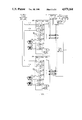
- FIG. 4 represents an arrangement for interconnecting switch units with inter-switch unit trunks
- FIGS. 5 and 6 are flow diagrams of processes for connecting inter-switch unit trunks to a trunk serving arrangement
- FIG. 7 is a flow diagram of a call completion process.
- the time division switching system of FIG. 1 is used to interconnect subscriber sets such as subscriber sets 23 through 26 and trunks such as trunks 43 through 46 and includes a time-multiplexed switch 10 comprising a time-shared space division switch having 64 input terminals and 64 output terminals. Also included is a plurality of time-slot interchange units of which representative time-slot interchange units 11 and 12 are specifically shown. Each time-slot interchange unit 11 and 12 includes a bi-directional time-slot interchanger and is connected to two input terminals and two output terminals of time-multiplexed switch 10. In FIG. 1 time-slot interchange unit 11 is connected to two time-multiplexed switch input terminals via time-multiplexed lines 13 and 14 and to two output terminals, via time-multiplexed lines 15 and 16.
- input/output terminal pairs are referred to as input/output terminal pairs. This term is used since the source for data words to an input terminal of a given input/output terminal pair is also the destination for data words from the output terminal of that pair.
- input/output terminal pair P1 is associated with time-multiplexed lines 13 and 15. Each time-multiplexed line 13 through 16 conveys digital information in 125 microsecond frames each comprising 256 time separated channels. Accordingly, each time-slot interchange unit transmits and receives up to 512 channels of digital information during each 125 microsecond frame.
- Each time-slot interchange unit is uniquely associated with a control unit of which control unit 17 is associated with time-slot interchange unit 11, and control unit 18 is associated with time-slot interchange unit 12. Additionally, each time-slot interchange unit is connected via individual time-multiplexed lines to a plurality of peripheral units of which line units 19 through 22 and trunk units 39 through 42 and 110 through 113 are shown in FIG. 1.
- a time-slot interchange unit, its associated control unit and peripheral units are collectively referred to herein as a switching module which is represented in FIG. 1 as switching modules 201 and 202.
- Switch module 201 comprises line units 19 and 20, trunk units 39 and 40 trunk units 110 and 111 and time-slot interchange unit 11 while switching module 202 comprises line units 21 and 22, trunks units 41 and 42 trunk units 112 and 113 and time-slot interchange unit 12.
- Each of the line units is connected to a number of subscriber sets of which subscriber sets 23 through 26 are shown. The exact number of line units associated with each time-slot interchange unit and the exact number of subscriber sets associated with each line unit is determined by the number of subscribers to be served and the calling rates of those subscribers.
- Each line unit terminates the analog loop of the well-known type from a plurality of subscriber sets, e.g., 23 through 26, and converts call information including analog speech signals into digital data words which are transmitted to its associated time-slot interchange unit.
- each line unit detects service requests from the subscriber sets and generates certain signaling information for those subscriber sets.
- the particular subscriber sets from which speech samples are taken and encoded, and the particular time-multiplexed channels used to transmit the resulting code between the line unit and its associated time-slot interchange unit are determined by the control unit of the associated time-slot interchange unit.
- the trunk units e.g. 39 and 40, perform analogous functions for trunks such as detecting trunk seizures and sending and receiving trunk signaling to and from other systems.
- the trunks can be either of the analog or digital type.
- One example of a digital trunk is the T1 carrier system disclosed in the J. H. Green et. al., U.S. Pat. No. 4,059,731, on which 24 separate communication channels are multiplexed.
- Line unit 19 scans the lines connected to each subscriber set to detect requests for service. When such a request is detected, line unit 19 transmits to control unit 17, a message indicating the request and the identity of the requesting subscriber set. This message is tranmitted to control unit 17 via a communication path 27.
- Control unit 17 performs the necessary translation based on the service requested, the identity of the requesting subscriber set and the available equipment, and transmits a message to line unit 19 via communication path 27 defining which of the plurality of time separated channels between line unit 19 and time-slot interchange unit 11 is to be used to transmit information from subscriber set 23 to time-slot interchange unit 11.
- line unit 19 encodes the analog information from subscriber set 23 into digital data words and transmits the resulting data words in the assigned channels.
- FIG. 3 represents the digital data word format used in the present system which format includes an 8-bit data portion and a 7-bit signaling portion.
- Line unit 19 also transmits in the signaling bit position labeled A (the A-bit) of the assigned channel an indication of the DC state, i.e., open circuit/closed circuit of the subscriber loop associated with subscriber set 23.
- control unit 17 After a time separated channel between line unit 19 and time-slot interchange unit 11 is assigned to a given subscriber set, control unit 17 detects signaling information from the subscriber set by sampling the information transmitted in the assigned channel. Such sampling operations are performed via a communication path 28. Control unit 17 responds to the signaling information from the subscriber's channel, and to control messages from other control units, e.g., 18, and a central control unit 30, by controlling the time-slot interchange function of the time-slot interchange unit 11.
- the first type consists of inter-office trunks represented by trunks 43 through 46 which are connect to other switching systems.
- the second type is comprised of trunks 114 through 116 to other switching modules of the switching system. Trunks, e.g., 115 to other switching modules of the same switching system are referred to herein as inter-switch module trunks.
- the inter-switch module trunks are used to advance connections between switch modules when paths through the time-multiplex 10 are not available. In normal operation, when communication paths though the time-multiplex switch 10 are available, the inter-switch module trunks are inactive and trunk services, such as scanning and signaling, are not provided to them.
- Trunk services are provided to the inter-office trunks, however, so that connections to other switching offices can be completed.
- trunks receiving trunk services are referred to as active trunks and trunks which do not receive trunks services are referred to as inactive trunks.
- inactive trunks The use of inter-switch module trunks is discussed later herein.
- the inter-office trunks e.g., 43 and 44 are assigned a time-separated channel into the time-slot interchange unit at system initialization and do not require the assignment of a channel when trunk activity begins (origination).
- the trunk units e.g., 39 and 40 of the embodiment detect trunk signaling such as trunk seizure and reflect this signaling in the A-bit of the pre-assigned channel.
- Inband signaling such as MF tones, is conveyed to the time-slot interchange unit via the PCM data portion of the assigned channel.
- Control unit 17 detects trunk signaling via the communication path 28 in the same manner that subscriber signaling is detected.
- each time-multiplexed line between a time-slot interchange unit and the time-multiplexed switch 10 has 256 channels each 125 microsecond frame. These channels are assigned numerical designations from 1 to 256 in sequence as they occur. This sequence of channels recurs so that a given channel will be available every 125 microseconds.
- the time-slot interchange function takes the data words received from the line and trunk units and places them in channels on the time-multiplexed line between the time-slot interchange units and the time-multiplexed switch 10 under the control of control units 17 and 18.
- Time-multiplexed switch 10 operates in recurring frames of time-slots where each 125 microsecond frame comprises 256 time-slots. During each time-slot, time-multiplexed switch 10 is capable of connecting data words received at any of its 64 input terminals to any of its 64 output terminals in accordance with time-slot control information stored in a control memory 29. The configuration pattern of connections through time-multiplexed switch 10 repeats itself every 256 time-slots and each time-slot is assigned a numerical designation in sequence from 1 to 256.
- Time-slot control information is written into control memory 29 by central control 30 which generates this control information from control messages obtained from various control units, e.g., 17 and 18.
- Central control 30 and control units 17 and 18 exchange control messages utilizing selected channels called control channels of the time-multiplexed lines, e.g., 13 through 16, between the time-slot interchange units and the time-multiplexed switch 10.
- Each control message comprises a plurality of control words and each control channel can transmit one control word per frame of 256 time separated channels.
- the same channel of the two time-multiplexed lines associated with a given input/output terminal pair is predefined to be a control channel. Additionally, a given channel is used as a control channel for only one pair of time-multiplexed lines.
- time-multiplexed switch 10 connects the data word occupying that control channel to output terminal P64 and connects input terminal P64 to the output terminal associated with the above-mentioned control channel.
- channel 1 is the control channel for time-multiplexed lines 13 and 15, and channel 2 is the control channel for time-multiplexed lines 14 and 16.
- time-slot TS 1 information from control memory 29 defines, among other connections, that the control word in channel 1 of time-multiplexed line 13 is connected to output terminal P64 and that the control word in channel 1 at input terminal P64 is connected to time-multiplexed line 15.
- time-slot TS 2 information from control memory 29 defines that the control word in channel 2 of time-multiplexed line 14 is connected to output terminal P64 and that the control word in channel 2 at input terminal P64 is connected to time-multiplexed line 16.
- output terminal P64 When operating in this manner, output terminal P64 receives from time-multiplexed switch 10 all control words in a channel having the same numerical designation in which they were transmitted to the time-multiplexed switch. Further, each control channel is connected to receive control words from input terminal P64 during the time-slot having the same numerical designation as their associated control channel. Control words switched to output terminal P64 are transmitted to a control distribution unit 31 which temporarily stores them in a location associated with that control channel. The association of control channels with storage locations in control distribution unit 31 identifies the source of the information stored.
- Each control message from a time-slot interchange unit comprises a destination portion and a signaling information portion.
- the destination portion uniquely defines the expected destination of the signaling portion of the control message.
- Control distribution unit 31 interprets the destination portion of each control message to determine the proper destination for the control message and retransmits the message to input terminal P64 of time-multiplexed switch 10 in a channel having the same numerical designation as the control channel associated with the destination unit.
- time-slot interchange unit 11 transmits control messages to time-slot interchange unit 12 by transmitting control words during its recurring control channel to form a control message having a destination portion identifying time-slot interchange unit 12.
- Control distribution unit 31 accumulates the control words, interprets the destination portion, and retransmits the message to input terminal P64 during the channel having the same numerical designation as the control channel associated with time-slot interchange unit 12.
- a control message can also be transmitted to central control 30 by defining central control 30 in the destination portion of the control message.
- control distribution unit 31 transmits the message to central control 30 via a communication link 32 rather than returning it to time-multiplexed switch 10.
- a message may be transmitted from central control 30 to one of the time-slot interchange units by transmitting to the control distribution unit 31 a control message having a destination portion defining the particular time-slot interchange unit. This transmission is also accomplished utilizing communication link 32.
- the operation of the system shown in FIG. 1 is described in detail in the above-cited Beuscher et. al. U.S. Pat. No. 4,322,843.
- the control messages exchanged among units, e.g., 17 and 18 and the central control 30 are used to advance call completion and to determine the status of the switching system and its parts.
- Normal call processing involves the receipt of call signaling information from a line or trunk unit at one switch module, the transmission of a control message from the receiving switch module to central control 30 defining the incoming call and the transmission of control messages to the receiving and call destination switch modules defining the path through the time-multiplex switch 10 to be used for call completion.
- the involved switching modules then connect the appropriate lines or trunks to the defined time-multiplex switch 10 path.
- the exchange of call completion control messages coordinates the operation the involved switching modules and the central control 30 and relies on a decision by the central control for the time-multiplex switch 10 path to be used.
- Each control unit e.g., 17 and 18 periodically transmits a communication check control message to the central control 30 which replies with a predictable response message to the source control unit.
- a control unit, e.g., 17 which does not receive appropriate response messages from central control 30, assumes a failure of the central control or the time-multiplex switch communication link thereto and changes its status to the stand alone mode. In the stand alone mode a control unit is responsible for reacting to input stimuli without assistance from the central control and without paths though the time-multiplex switch 10.
- Each control unit includes a location in its memory 57 which is marked to indicate stand alone status of that control unit.
- Central control 30 expects communication check messages from each control unit, e.g., 17 at a predetermined periodic rate. Central control 30 detects when such such messages are not properly received, marks the delinquent control unit as unavailable in the central control memory and transmits unavailability control messages to the other control units. The control units respond to the unavailability message from central control 30 by marking the unavailable control unit as being in the stand alone mode in their individual control unit memory 57 (FIG. 2).
- Memory 57 (FIG. 2) of each control unit, e.g., 17 stores the program for the control of its associated control unit and data regarding the function of the control unit, its associated time-slot interchange unit and its associated subscribers and trunks.
- the data stored in memory 57 includes translation tables for translating calling information into information identifying the routing for a call and information defining the status, e.g., stand alone of all switching modules, e.g., 201 and 202.
- the main processing entity of control unit 17 is a processor 66 which operates in response to instructions and data stored in memory 57.
- Control unit 17 includes a control interface circuit 56 which receives instructions from processor 66 via a bus 59 and in response thereto, communicates with the peripheral units, e.g., line units 19 and 20, via communication path 27.
- a DMA unit 58 is also included in control unit 17 and is used in conjunction with an interface unit 69 to transmit and receive the control messages on time-multiplexed lines 13 through 16 to and from the time-multiplex switch 10.
- Each of the line and trunk units transmits recurring frames of information each comprising 32 channels of 16 bits each. This information is transmitted to a multiplex unit 60 (FIG. 2) within time-slot interchange unit 11. Multiplex unit 60 receives the output signals from the peripheral units which signals are selectively transmitted on an output time-multiplexed line 62 having 512 channels for each 125 microsecond frame. The connection of peripheral unit channels to the channels of time-multiplex line 62 by multiplex unit 60 is controlled by information stored in a control RAM 71 which is cyclically accessed at the time-multiplexed line 62 rate.
- Control information is written into control RAM 71 by processor 66 at the time of system initialization to connect a predetermined number of subscriber line channels and to connect the channels from inter-office trunks to the channels on line 62. No channel from an inter-switching module trunk is connected through multiplex unit 60 at initialization.
- a demultiplex circuit 61 receives 512 channels of 16 bits each on a time-multiplexed line 63 which channels are distributed, in a manner determined by the information stored in control RAM 71, to the peripheral unit channels connected to the line and trunk units, e.g., 19 and 40.
- the operation of demultiplexer unit 61 complements the operation of multiplex unit 60 so that bi-directional communication with peripheral units is achieved.
- the information in a given channel on time-multiplex line 62 is transmitted via a gate 52 and a path 62' to a receive time-slot interchanger 50 where it is stored in a memory location uniquely associated with that channel.
- the particular memory location of receive time-slot interchange 50 into which a given data word is stored is defined by time-slot designation signals generated by time-slot counter 54.
- Time-slot counter 54 generates a recurring sequence of 512 time-slot designations at the rate of one time-slot designation per time-slot.
- the particular time-slot designation generated during the time-slot in which a given data word is received defines the memory location within receive time-slot interchanger 50 which is to store that data word.
- Data words are also read from receive time-slot interchanger 50 at the rate of one data word per time-slot.
- the memory address of the data word to be read from receive time-slot interchanger 50 during a given time-slot is obtained by reading control RAM 55.
- Control RAM 55 is read once per time-slot at an address defined by the time-slot designation from time-slot counter 54 and the quantity so read is transmitted to receive time-slot interchanger 50 as the read address for that time-slot.
- Time-multiplexed switch 10 Data words read from receive time-slot interchanger 50 are transmitted to time-multiplexed switch 10 via a time-multiplexed line 68, a gate 8, a time-multiplexed line 68' and an interface unit 69. Data words from time-multiplexed switch 10 are received by time-slot interchange unit 11 by interface unit 69, and are conveyed via a time-multiplexed line 70', a gate 9 and a time-multiplexed line 70 to transmit time-slot interchanger 53.
- control RAM 55 effects the operation of gates 8 and 9 such that data words transmitted by receive time-slot interchanger 50 on time-multiplexed line 68 are conveyed via gates 8 and 9 and time-multiplexed line 70 to transmit time-slot interchanger 53.
- Transmit time-slot interchanger 53 stores the incoming data words in a location defined by an address from control RAM 55. Data words are read from transmit time-slot interchanger 53 at the address defined by the time-slot counter 54. Data words so read are transmitted on time-multiplexed line 63 for transmission to the peripheral units, e.g., line unit 19.
- control RAM 55 may be implemented as a number of control memories, each associated with a particular circuit, e.g., transmit time-slot interchanger 53. The particular configuration of control memories is not important to the present description and may vary depending on timing and circuitry requirements within the time-slot interchange unit 11.
- time-slot interchanger 50 The general principles of time-slot interchange as performed by the receive time-slot interchanger 50, the control RAM 55, the time-slot counter 54 and the transmit time-slot interchanger 53 are well known in the art and not described in greater detail herein.
- One arrangement for reading and writing data words in time-slot memories is described in detail in U.S. Pat. No. 4,035,584, J. W. Lurtz.
- Trunk services such as scanning and signaling are provided by the control unit 17 which includes a signal processor 65 and a digital service unit 67.
- Signal processor 65 reduces the real time load requirement of processor 66 by receiving and analyzing the signaling portion (bits A through G, FIG. 3) of each data word received on line 62 from line and trunk units and by transmitting signaling bits to the line and trunk units.
- Processor 66 reads the signaling information of each incoming channel on time-multiplex line 62' from signal processor 65. This information, as attributed by processor 66 to the line or trunk connected to a channel, shows line or trunk status for call processing purposes.
- Signal processor 65 also transmits signaling information.
- Signaling bits are passed from the processor 66 to signal processor 65 along with indications of their destination channel on outgoing time-multiplex line 63.
- Signal processor 65 then controls the signaling bits A through G of the outgoing channels via the path 64 to transmit signaling information to the line and trunk units.
- Digital service unit 67 receives the PCM data portion of each data word received by line 62' from the line and trunk units to detect PCM tone signals from subscribers and trunks.
- the processor 66 periodically reads the received signaling information from the digital services unit 67 to detect line and trunk signaling.
- Digital service unit 67 is also used to transmit tones and signals in PCM format via a gate 51 to subscribers and trunks and via a gate 52 to time-multiplex switch 10. Definitions of the tones and signals are sent from processor 66 to digital service unit 67 which places signals in appropriate channels.
- the primary mode of control information exchange comprises the transmission of control messages from a source time-slot interchange unit through the time-multiplexed switch 10 and the control distribution unit 31 and back to the destination time-slot interchange unit.
- a secondary mode of communication is also used whereby control information with regard to a given call is transmitted from the source time-slot interchange unit to the destination time-slot interchanger unit via time-multiplexed switch 10 utilizing the time-slot assigned for that call.
- the E-bit position of the data word in an active call time-slot is used for the secondary mode communication. However, it can be seen that any or all of the signaling bits could be used in this secondary communication mode.
- the E-bit serves the dual purpose of signal acknowledgement during the establishment of a path through the time-multiplexed switch 10 and continuing path continuity check during the connection.
- the operation of E-bit accumulator 48 and E-bit check circuit 192, which communicates with processor 66 via conductors 193, 194, and 195 in performing these dual purposes is described in detail in the above-cited Beuscher, et. al., U.S. Pat. No. 4,322,843.
- control messages between control units, e.g., 17 and 18 and the central control 30 are used to detect the unavailability of time-multiplex switch 10 for connections between switching modules.
- that switching module reconfigures itself to provide trunk services to the attached inter-switch module trunks.
- FIG. 5 is a flow diagram of the reconfiguration method used by a switching module which detects that it cannot use the time-multiplex switch 10 to advance connections.
- the unavailability of the time-multiplex 10 is detected in block 320 by the failure to receive control messages from the central control 30 as above discussed.
- a switching module proceeds to block 321 where information identifying the available inter-switch module trunks is read from memory 57 and written into RAM 71 to define the connections of inter-switching module trunks to channels on time-multiplex lines 62 and 63.
- the digital services unit 67 and the signal processor 65 are then used by processor 66 to provide trunk services to the inter-switch module trunks in block 322.
- central control 30 detects that a switching module cannot be accessed via the time-multiplex switch 10 control messages are sent to the other switching modules notifying them of the unavailability of the time-multiplex 10 for connection to the inaccessible switching module.
- the central control 30 includes in its data base information identifying the inter-switching module trunks between all switching modules.
- the central control 30 detects an inaccessible switching module it transmits a message to each other switching module indicating the unavailability and identifying inter-switch module trunks between the inaccessible switching module and the switching module receiving the message. This message is received by a switching module in block 330 (FIG. 6).
- the receiving switching module responds to the unavailability message by loading RAM 71 with information to connect (block 331) each inter-switch module trunk identified by the message from central control 30 to the time-multiplex lines 62 and 63.
- the newly connected trunks are then served (block 332) as discussed above.
- trunk services are provided to any trunk (either inter-switch module or inter-office) connected to a channel on time-multiplex lines 62 and 63. Connection of a trunk to channels on time-multiplex lines 62 and 63 also enables the switching of information to and from that trunk by the time-slot interchange unit, e.g., 11.
- FIG. 4 represents a time division switching system of the type disclosed in FIG. 1 and components having the same reference numeral as like components in FIG. 1 are the same.
- the system shown in FIG. 4 comprises three representative switch modules 200 through 202. These switch modules are interconnected by bi-directional inter-switch module trunks 114, 115 and 116. Trunk 114 connects trunk unit 113 of switch module 202 to trunk unit 103 of switch module 200, trunk 115 connects trunk unit 112 of switch module 202 to trunk unit 111 of switch module 201 and trunk 116 connects trunk unit 110 of switch module 201 to trunk unit 104 of switch module 200.
- time-multiplex switch 10 is available for connections between all switching modules and all the trunks 114 through 116 are inactive. That is, they are not connected to time-multiplex lines 62 and 63 (FIG. 2) of any time-slot interchange unit 11 and accordingly they receive no trunk services.
- the control unit of each switching module 200 through 202 periodically transmits messages to central control 30 in order to determine continuing time-multiplex switch 10 of availability.
- the central control 30 responds to each received message so that the switching modules know of the continued availability.
- switching module 201 detects the absence of messages from central control 30 and performs the previously described sequence of FIG. 5 to make all of the its inter-switching module trunks active by connecting them to time-multiplex lines 62 and 63 of time-slot interchange unit 11. Thus, trunk services are provided to trunks 115 and 116 at switching module 201.
- Central control 30 detects the absence of messages from switching module 201 and determines that switching module 201 cannot communicate through the time-multiplex switch 10, that is, it is in the the stand alone mode. Central control 30 then searches its memory to determine which inter-switch module trunks, e.g., 114 through 116 can be used to communicate between switching module 201 and the other switching modules 200 and 202 of the system. Trunk 115 to switching module 202 and trunk 116 to switching module 200 are found in this search. Unavailability messages are then transmitted by central control 30 to switching module 202 identifying trunk 115 and to switching module 200 identifying trunk 116. In response switching modules 200 and 202 follow the procedures described with regard FIG. 6 to provide trunk services to trunk 116 and 115, respectively. In FIG. 4 the trunk units 104, 110, 111, and 112 which are connected to newly activated trunks 115 and 116 include a darkened triangle in the upper left corner to represent that they are receiving trunk service.
- the trunk units 104, 110, 111, and 112 which are
- FIG. 7 is a flow diagram of the procedures performed by all switching modules, e.g., 202 in the completion of connections.
- the switching system of FIG. 4 operates in accordance with the call processing routine of FIG. 7 which is described in terms of exemplary call from subscriber set 26 of switching module 202 to subscriber set 24 of switching module 201.
- Control unit 18 (block 301, FIG. 7), by means described with regard to FIGS. 1 through 3, detects when subscriber set 26 goes off-hook and begins to collect the dialed digits.
- the dialed digits define subscriber set 24 of switch module 201.
- the call processing routine proceeds to block 303 where the switching module status is checked and a decision is made to use normal time-multiplex switch routing or the alternative inter-switch module trunk routing.
- the status information stored in memory 57 (FIG. 2) is read to make this decision.
- a switching module e.g., 202 is not in the stand alone mode the routing process continues from block 303 via path 311 to block 309.
- control unit 18 transmits a control message identifying the called number at switching module 201 to central control 30. Since, in the present example, switching module 201 is unavailable via the time-multiplex switch 10 central control 30 returns a message to control unit 18 identifying that newly activated inter-switch module trunk 115 is to be used to complete the call. In response to the message from central control 30 control unit 18 recognizes in block 310 that inter-switch module trunk 115 is to be used to complete the call and proceeds to block 306 (had a time-multiplex switch 10 connection been available, the switching module 202 would have proceeded to block 308 where a specified time-multiplex switch 10 path would have been used).
- control unit 18 seizes trunk 115 which is presently receiving scanning and signaling trunk services from switch module 202 and proceeds to send representations of the dialed digits on trunk 115 in response to the appropriate acknowledgement signals from switching module 201.
- Switching module 202 finally completes path 205 between subscriber set 26 and trunk 115 (block 307).
- the completed path consists of receive time-slot interchange 50, gates 8 and 9 and transmit time-slot interchange 53 as previously discussed.
- switch module 201 starts a call processing program as shown in FIG. 7 in response to the seizure of trunk 115 by switching module 202.
- Switching module 201 completes the origination with acknowledgement signals (block 301) and collects the digits from trunk 115 in block 302.
- the call processing routine in switching module 201 determines from the status information in its memory 57 (FIG. 2) that it is in the stand alone mode (block 303) and proceeds via path 304 to block 305.
- Control unit 17 consults its translation table (block 305) using the digits received from trunk 115 and determines that they represent subscriber set 24.
- Switching module 201 then signals subscriber set 24 (block 306) and completes the path 206 between line unit 20 and trunk 115 (block 307) upon answer at subscriber set 24. Subscriber set 24 is then connected to subscriber set 26 via the path provided by path 205 through time slot interchange unit 12, the trunk 115 and the path 206 through time-slot interchange unit 11. This path is an alternative to the unavailable (in the present example) path through time-multiplex switch 10.
Abstract
Description
Claims (18)
Priority Applications (5)
| Application Number | Priority Date | Filing Date | Title |
|---|---|---|---|
| US07/356,802 US4979164A (en) | 1989-05-24 | 1989-05-24 | Switching system reliability |
| DE1990628443 DE69028443T2 (en) | 1989-05-24 | 1990-05-16 | Operational safety improvement in switching systems |
| EP90305269A EP0399723B1 (en) | 1989-05-24 | 1990-05-16 | Improvement in switching system reliability |
| ES90305269T ES2091792T3 (en) | 1989-05-24 | 1990-05-16 | IMPROVING THE RELIABILITY OF A SWITCHING SYSTEM. |
| JP2132782A JPH0799879B2 (en) | 1989-05-24 | 1990-05-24 | Telecommunication switching system |
Applications Claiming Priority (1)
| Application Number | Priority Date | Filing Date | Title |
|---|---|---|---|
| US07/356,802 US4979164A (en) | 1989-05-24 | 1989-05-24 | Switching system reliability |
Publications (1)
| Publication Number | Publication Date |
|---|---|
| US4979164A true US4979164A (en) | 1990-12-18 |
Family
ID=23403006
Family Applications (1)
| Application Number | Title | Priority Date | Filing Date |
|---|---|---|---|
| US07/356,802 Expired - Lifetime US4979164A (en) | 1989-05-24 | 1989-05-24 | Switching system reliability |
Country Status (1)
| Country | Link |
|---|---|
| US (1) | US4979164A (en) |
Cited By (15)
| Publication number | Priority date | Publication date | Assignee | Title |
|---|---|---|---|---|
| US5107489A (en) * | 1989-10-30 | 1992-04-21 | Brown Paul J | Switch and its protocol for making dynamic connections |
| US5115425A (en) * | 1990-05-31 | 1992-05-19 | At&T Bell Laboratories | Switching system reliability |
| US5404350A (en) * | 1993-04-22 | 1995-04-04 | At&T Corp. | Routing calls destined for inaccessible destinations |
| US5412645A (en) * | 1991-08-09 | 1995-05-02 | Westinghouse Electric Corporation | Distributed processing telecommunication switch with standardized switch units |
| US5416772A (en) * | 1993-08-20 | 1995-05-16 | At&T Corp. | Apparatus for insertion of overhead protocol data into a switched data stream |
| US5418776A (en) * | 1993-02-26 | 1995-05-23 | At&T Corp. | Emergency local switching |
| EP0760591A2 (en) * | 1995-08-31 | 1997-03-05 | AT&T Corp. | Method and apparatus for interfacing low speed access links to a high speed time multiplexed switch fabric |
| US5661721A (en) * | 1995-01-13 | 1997-08-26 | Fujitsu Limited | Method of and apparatus for receiving concentrated calls |
| US5896371A (en) * | 1990-07-27 | 1999-04-20 | Kabushiki Kaisha Toshiba | Broadband switching networks |
| US5923652A (en) * | 1995-12-16 | 1999-07-13 | Alcatel Alsthom Compagnie Generale D'electricite | Method for tying additional function modules into a controlling facility of a switching system, and a switching system |
| US6058182A (en) * | 1997-11-07 | 2000-05-02 | At&T Corporation | Communications switch permitting transparent maintenance of switch control system |
| US6438144B1 (en) * | 1999-03-11 | 2002-08-20 | Eci Telecom Ltd. | Communication system with two stage multiplexing |
| US6636513B1 (en) * | 1995-09-06 | 2003-10-21 | Fujitsu Limited | Switching system |
| US6850517B1 (en) | 1998-06-05 | 2005-02-01 | Nec Corporation | System and method for high-capacity electronic switching |
| US6985487B1 (en) | 1990-07-27 | 2006-01-10 | Kabushiki Kaisha Toshiba | Broadband switching networks |
Citations (2)
| Publication number | Priority date | Publication date | Assignee | Title |
|---|---|---|---|---|
| US3217109A (en) * | 1961-12-26 | 1965-11-09 | Bell Telephone Labor Inc | Distributed telephone switching system |
| US4583218A (en) * | 1983-05-11 | 1986-04-15 | At&T Bell Laboratories | Control communication in a switching system having clustered remote switching modules |
-
1989
- 1989-05-24 US US07/356,802 patent/US4979164A/en not_active Expired - Lifetime
Patent Citations (2)
| Publication number | Priority date | Publication date | Assignee | Title |
|---|---|---|---|---|
| US3217109A (en) * | 1961-12-26 | 1965-11-09 | Bell Telephone Labor Inc | Distributed telephone switching system |
| US4583218A (en) * | 1983-05-11 | 1986-04-15 | At&T Bell Laboratories | Control communication in a switching system having clustered remote switching modules |
Non-Patent Citations (2)
| Title |
|---|
| G. Zorpette, "Keeping the Phone Lines Open", IEEE Spectrum, vol. 26, No. 6, Jun. 1989, pp. 32-36. |
| G. Zorpette, Keeping the Phone Lines Open , IEEE Spectrum, vol. 26, No. 6, Jun. 1989, pp. 32 36. * |
Cited By (17)
| Publication number | Priority date | Publication date | Assignee | Title |
|---|---|---|---|---|
| US5107489A (en) * | 1989-10-30 | 1992-04-21 | Brown Paul J | Switch and its protocol for making dynamic connections |
| US5115425A (en) * | 1990-05-31 | 1992-05-19 | At&T Bell Laboratories | Switching system reliability |
| US6219349B1 (en) | 1990-07-27 | 2001-04-17 | Kabushiki Kaisha Toshiba | Broadband switching networks |
| US5896371A (en) * | 1990-07-27 | 1999-04-20 | Kabushiki Kaisha Toshiba | Broadband switching networks |
| US6985487B1 (en) | 1990-07-27 | 2006-01-10 | Kabushiki Kaisha Toshiba | Broadband switching networks |
| US5412645A (en) * | 1991-08-09 | 1995-05-02 | Westinghouse Electric Corporation | Distributed processing telecommunication switch with standardized switch units |
| US5418776A (en) * | 1993-02-26 | 1995-05-23 | At&T Corp. | Emergency local switching |
| US5404350A (en) * | 1993-04-22 | 1995-04-04 | At&T Corp. | Routing calls destined for inaccessible destinations |
| US5416772A (en) * | 1993-08-20 | 1995-05-16 | At&T Corp. | Apparatus for insertion of overhead protocol data into a switched data stream |
| US5661721A (en) * | 1995-01-13 | 1997-08-26 | Fujitsu Limited | Method of and apparatus for receiving concentrated calls |
| EP0760591A2 (en) * | 1995-08-31 | 1997-03-05 | AT&T Corp. | Method and apparatus for interfacing low speed access links to a high speed time multiplexed switch fabric |
| EP0760591A3 (en) * | 1995-08-31 | 2000-05-17 | AT&T Corp. | Method and apparatus for interfacing low speed access links to a high speed time multiplexed switch fabric |
| US6636513B1 (en) * | 1995-09-06 | 2003-10-21 | Fujitsu Limited | Switching system |
| US5923652A (en) * | 1995-12-16 | 1999-07-13 | Alcatel Alsthom Compagnie Generale D'electricite | Method for tying additional function modules into a controlling facility of a switching system, and a switching system |
| US6058182A (en) * | 1997-11-07 | 2000-05-02 | At&T Corporation | Communications switch permitting transparent maintenance of switch control system |
| US6850517B1 (en) | 1998-06-05 | 2005-02-01 | Nec Corporation | System and method for high-capacity electronic switching |
| US6438144B1 (en) * | 1999-03-11 | 2002-08-20 | Eci Telecom Ltd. | Communication system with two stage multiplexing |
Similar Documents
| Publication | Publication Date | Title |
|---|---|---|
| US4943999A (en) | Switching system reliability | |
| EP0125602B1 (en) | Control communication in a switching system having clustered remote switching modules | |
| US4074072A (en) | Multiprocessor control of a partitioned switching network by control communication through the network | |
| US5086461A (en) | Apparatus and method for providing existing 1ESS and 1AESS telephone switching equipment with the capability of using the SS7 protocol | |
| US4322843A (en) | Control information communication arrangement for a time division switching system | |
| US4577312A (en) | Arrangement for wideband transmission via a switched network | |
| EP0425145B1 (en) | Method and apparatus for providing real-time switching of high bandwidth transmission channels | |
| EP0125605B1 (en) | Channel selection in a switching system having clustered remote switching modules | |
| US4720854A (en) | Architecture for distributed control telecommunication systems | |
| US4280217A (en) | Time division switching system control arrangement | |
| US4979164A (en) | Switching system reliability | |
| EP0190198B1 (en) | Time division switching system control arrangement and method | |
| US4558444A (en) | Switching system having selectively interconnected remote switching modules | |
| NL8603198A (en) | RESOURCES ALLOCATION FOR DIVIDED OPERATING SYSTEMS. | |
| US4296492A (en) | Continuity verification arrangement | |
| EP0125604B1 (en) | Switching system having remote switching capability | |
| EP0114822B1 (en) | Communication arrangements for distributed control systems | |
| US4972465A (en) | Switching system reliability | |
| EP0399723B1 (en) | Improvement in switching system reliability | |
| KR850006842A (en) | Line extension device of communication system | |
| JPS59174087A (en) | Channel matching system of decentralized control exchange | |
| KR100244782B1 (en) | Device and method for detecting cut-off call on digital switching system | |
| EP0115486A1 (en) | Time multiplex switch for time division switching systems | |
| JPH01185058A (en) | System for selecting incoming | |
| JPS6317279B2 (en) |
Legal Events
| Date | Code | Title | Description |
|---|---|---|---|
| AS | Assignment |
Owner name: BELL TELEPHONE LABORATORIES, INCORPORATED, A CORP. Free format text: ASSIGNMENT OF ASSIGNORS INTEREST.;ASSIGNOR:ARDON, MENACHEM T.;REEL/FRAME:005079/0370 Effective date: 19890523 Owner name: AMERICAN TELEPHONE AND TELEGRAPH COMPANY, A CORP. Free format text: ASSIGNMENT OF ASSIGNORS INTEREST.;ASSIGNOR:ARDON, MENACHEM T.;REEL/FRAME:005079/0370 Effective date: 19890523 |
|
| STCF | Information on status: patent grant |
Free format text: PATENTED CASE |
|
| FEPP | Fee payment procedure |
Free format text: PAYOR NUMBER ASSIGNED (ORIGINAL EVENT CODE: ASPN); ENTITY STATUS OF PATENT OWNER: LARGE ENTITY |
|
| FPAY | Fee payment |
Year of fee payment: 4 |
|
| FEPP | Fee payment procedure |
Free format text: PAYOR NUMBER ASSIGNED (ORIGINAL EVENT CODE: ASPN); ENTITY STATUS OF PATENT OWNER: LARGE ENTITY Free format text: PAYER NUMBER DE-ASSIGNED (ORIGINAL EVENT CODE: RMPN); ENTITY STATUS OF PATENT OWNER: LARGE ENTITY |
|
| FEPP | Fee payment procedure |
Free format text: PAYOR NUMBER ASSIGNED (ORIGINAL EVENT CODE: ASPN); ENTITY STATUS OF PATENT OWNER: LARGE ENTITY Free format text: PAYER NUMBER DE-ASSIGNED (ORIGINAL EVENT CODE: RMPN); ENTITY STATUS OF PATENT OWNER: LARGE ENTITY |
|
| FPAY | Fee payment |
Year of fee payment: 8 |
|
| FPAY | Fee payment |
Year of fee payment: 12 |