US4979209A - Individual subscriber line module - Google Patents
Individual subscriber line module Download PDFInfo
- Publication number
- US4979209A US4979209A US07/436,767 US43676789A US4979209A US 4979209 A US4979209 A US 4979209A US 43676789 A US43676789 A US 43676789A US 4979209 A US4979209 A US 4979209A
- Authority
- US
- United States
- Prior art keywords
- subscriber
- jack
- line
- plug
- telephone company
- Prior art date
- Legal status (The legal status is an assumption and is not a legal conclusion. Google has not performed a legal analysis and makes no representation as to the accuracy of the status listed.)
- Expired - Lifetime
Links
- 239000004020 conductor Substances 0.000 claims abstract description 34
- 230000035939 shock Effects 0.000 claims abstract description 13
- 244000261422 Lysimachia clethroides Species 0.000 claims description 11
- 230000000295 complement effect Effects 0.000 claims description 5
- 238000010276 construction Methods 0.000 description 4
- 239000000463 material Substances 0.000 description 3
- 239000007787 solid Substances 0.000 description 3
- 238000009434 installation Methods 0.000 description 2
- 238000012423 maintenance Methods 0.000 description 2
- 238000000034 method Methods 0.000 description 2
- 230000002860 competitive effect Effects 0.000 description 1
- 230000003831 deregulation Effects 0.000 description 1
- 230000009977 dual effect Effects 0.000 description 1
- 238000012986 modification Methods 0.000 description 1
- 230000004048 modification Effects 0.000 description 1
Images


Classifications
-
- H—ELECTRICITY
- H04—ELECTRIC COMMUNICATION TECHNIQUE
- H04Q—SELECTING
- H04Q1/00—Details of selecting apparatus or arrangements
- H04Q1/02—Constructional details
- H04Q1/028—Subscriber network interface devices
-
- H—ELECTRICITY
- H02—GENERATION; CONVERSION OR DISTRIBUTION OF ELECTRIC POWER
- H02G—INSTALLATION OF ELECTRIC CABLES OR LINES, OR OF COMBINED OPTICAL AND ELECTRIC CABLES OR LINES
- H02G3/00—Installations of electric cables or lines or protective tubing therefor in or on buildings, equivalent structures or vehicles
- H02G3/02—Details
- H02G3/08—Distribution boxes; Connection or junction boxes
- H02G3/14—Fastening of cover or lid to box
-
- H—ELECTRICITY
- H02—GENERATION; CONVERSION OR DISTRIBUTION OF ELECTRIC POWER
- H02G—INSTALLATION OF ELECTRIC CABLES OR LINES, OR OF COMBINED OPTICAL AND ELECTRIC CABLES OR LINES
- H02G3/00—Installations of electric cables or lines or protective tubing therefor in or on buildings, equivalent structures or vehicles
- H02G3/02—Details
- H02G3/08—Distribution boxes; Connection or junction boxes
- H02G3/16—Distribution boxes; Connection or junction boxes structurally associated with support for line-connecting terminals within the box
-
- H—ELECTRICITY
- H04—ELECTRIC COMMUNICATION TECHNIQUE
- H04Q—SELECTING
- H04Q1/00—Details of selecting apparatus or arrangements
- H04Q1/02—Constructional details
- H04Q1/021—Constructional details using pivoting mechanisms for accessing the interior of the apparatus
-
- H—ELECTRICITY
- H04—ELECTRIC COMMUNICATION TECHNIQUE
- H04Q—SELECTING
- H04Q1/00—Details of selecting apparatus or arrangements
- H04Q1/02—Constructional details
- H04Q1/11—Protection against environment
- H04Q1/116—Protection against environment lightning or EMI protection, e.g. shielding or grounding
Definitions
- This invention relates generally to new and improved telephone network interface apparatus, and more particularly relates to new and improved telephone network interface apparatus for interconnecting incoming telephone company wiring to subscriber premises wiring and for providing a demarcation point therebetween to determine whether a fault exists on the incoming telephone company wiring or the subscriber premises wiring and which apparatus selectively allows for both individual subscriber and telephone company personnel access to the interior of the apparatus.
- This invention also relates to a new and improved individual subscriber line module which may be provided with a lockable subscriber security cover for denying other subscribers access to the individual subscriber's terminals.
- prior art telephone network interface apparatus which include individual subscriber line modules but such prior art modules typically, as is still further known, unwantedly require that an entire module be discarded if a single non-function occurs in any component of the module. Accordingly, there exists a need in this art for new and improved telephone network interface apparatus of increased modularity, and for new and improved individual subscriber line modules which, upon the occurrence of a non-function in a single component of a module requires that less than the entire module be discarded.
- telephone network interface apparatus are known to the prior art which include individual subscriber line modules provided with individual security covers for denying other subscribers access to an individual subscriber's line. These individual security covers are typically locked in place by a padlock, and the construction of the prior art telephone network interface apparatus is such that in the event the individual subscriber moves away and leaves the padlock locked in place, telephone company personnel upon opening of the telephone company cover can remove the locked padlock and gain access to the subscriber's individual line.
- Such prior art telephone network apparatus perform generally well, there exists a need in such apparatus for improved structure for facilitating removal of the locked padlock by the telephone company personnel in a more efficient and less time consuming manner than is presently required with such prior art telephone network interface apparatus.
- a ringing voltage is applied to the incoming telephone line; the typical ringing voltage is 120 volts, two seconds on and two seconds off.
- the subscriber line module including a pair of exposed subscriber terminals to which the subscriber premises line is connected, and upon such subscriber terminals being connected to the incoming telephone line through a plug plugged into a jack, the subscriber can be exposed to potential ringing voltage shock hazard upon the subscriber inadvertently touching the subscriber terminals while the ringing voltage is applied thereto. Accordingly, there exists a need in the art to prevent such subscriber potential ringing voltage shock hazard.
- Individual security subscriber line modules satisfying the foregoing needs may, in accordance with the teachings of the present invention, include a generally rectangular, hollow box-like structure including a top, bottom, opposed sides and opposed first and second ends, such structure providing an internal space for receiving an individual circuit; a pair of subscriber wiring terminals mounted on the top for connection to a subscriber line, a plug connected to the pair of subscriber wiring terminals by first electrical conductors; a jack mounted on the top and provided with second electrical conductors for connecting the jack to the incoming telephone company line, the jack for having the plug plugged therein to interconnect the pair of subscriber wiring terminals and thereby the subscriber line to the incoming telephone company line and the plug for being unplugged from the jack to provide a demarcation point between the subscriber line and incoming telephone company line, and upon the plug being unplugged from the jack the jack for receiving the plug of an operating telephone to facilitate determination of whether a fault exists on the subscriber line or the incoming telephone company line; and mounting structure for mounting the module
- Such individual subscriber line module may be provided with an individual security cover mounted pivotally on one end of the top of the box-like structure and for being covering and being locked over the pair of subscriber terminals. Further, such individual subscriber line module may include safety structure for preventing potential ringing voltage shock hazard to the subscriber at the subscriber wiring terminals upon telephone ringing voltage being applied over the incoming telephone company line and ultimately to the subscriber wiring terminals.
- FIG. 1 is a front perspective view of telephone network interface apparatus embodying the present invention
- FIG. 2 is a front perspective view of the apparatus showing the subscriber cover in the open position
- FIG. 3 is a front view of the apparatus showing both the subscriber and telephone company covers in the open positions;
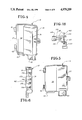
- FIG. 4 is a front perspective view of the telephone company cover of the apparatus
- FIG. 5 is a front view of the telephone company cover of the apparatus
- FIG. 6 is a left side view of the telephone company cover of FIG. 5;
- FIG. 7 is a perspective view of a replaceable individual subscriber line module embodying the present invention and including a replaceable subscriber wiring bridge and plug/cable;
- FIG. 8 is an exploded view of the replaceable individual subscriber line module of FIG. 7;
- FIG. 9 is a top view of the replaceable individual subscriber line module of FIGS. 7 and 8 but with the replaceable subscriber wiring bridge and plug/cable being removed;
- FIG. 10 is a side view of the replaceable individual subscriber line module of FIG. 7;
- FIG. 11 s a front perspective view of an alternate embodiment of telephone network interface apparatus embodying the present invention and with the subscriber cover being shown in the open position;
- FIGS. 12, 13 and 14 are, respectively, top, side elevation, and right end views of an alternate embodiment of a replaceable individual subscriber line module embodying the present invention and including a top security cover;
- FIG. 15 is a perspective view of a security staple embodied in the replaceable individual subscriber line module of FIGS. 12, 13 and 14;
- FIG. 16 is a top view of the replaceable individual subscriber line module of FIGS. 12, 13 and 14 showing a locked padlock positioned on top thereof;
- FIG. 17 is a side view of the replaceable individual subscriber line module of FIGS. 11, 12 and 13 showing the security cover in the unlocked and open position;
- FIG. 18 is a partial side view, partially in cross-section, showing the cooperating means of the present invention for locking the security cover of the alternate embodiment replaceable individual subscriber line module to deny access to other subscribers;
- FIG. 19 is a side elevational view of an alternate embodiment of a replaceable individual subscriber line module embodying the present invention and including an individual security cover shown in the open position;
- FIG. 20 is an elevational view of the individual subscriber line module shown in line 19 with the individual subscriber cover shown in the open position;
- FIG. 21 is a top view of a further alternate embodiment of replaceable individual subscriber line module embodying the present invention with the individual subscriber cover thereof shown in the closed, position;
- FIG. 22 is a side elevational view of the individual subscriber line module shown in FIG. 21 with the individual subscriber cover thereof shown in the open position;
- FIG. 23 is a perspective view of the alternate individual subscriber line module of FIGS. 21 and 22 with the individual subscriber cover shown in the open position;
- FIG. 24 is a top view of the alternate individual subscriber line module embodiment of FIGS. 21-23 with the individual subscriber cover removed.
- Apparatus 10 includes a base 12, telephone company cover 14, and subscriber cover 16.
- the base 12 includes a bottom 20 and an outwardly extending wall indicated by general numerical designation 22 circumscribing the bottom;
- the wall 22 includes opposed first and second wall portions 23 and 24 and opposed third and fourth wall portions 25 and 26.
- the bottom 20 and wall 22 provide a compartment indicated by general numerical designation 28 which compartment is divided generally into opposed first and second compartment portions 31 and 32 and which compartment division may be readily understood by reference to the diagrammatical dividing line 33 of FIG. 3.
- the first compartment portion 31 may be understood to be the telephone company compartment portion
- the second compartment portion 32 may be understood to be the subscriber compartment portion.
- the telephone company cover 14 includes opposed first and second portions 36 and 37 with the first portion 36 being solid and for overlying and closing the first compartment portion 31 (FIG. 3) and with the second cover portion 37 being provided with an opening 38 for overlying and exposing the second compartment portion 32 (FIG. 3) to the exterior upon the telephone company cover 14 being closed.
- the telephone company cover 14 is for being fastened only to the base 12 such as for example by a hex-headed screw 49 which is not easily removable by a subscriber and which requires a special type of tool not typically possessed by the subscriber but which tool typically is possessed by telephone company personnel.
- the telephone company cover 14 is provided with outwardly extending hinge members 41 and 42 for wedgedly and pivotally engaging corresponding outwardly extending hinge members 43 and 44 (FIG. 2) provided on the second wall portion 24 of the base 12 to mount the telephone company cover pivotally to the base 12.
- the subscriber cover 16 is solid and is for overlying only the second portion 37 of the telephone company cover 14 and further is for overlying and closing only the second compartment portion 32.
- the subscriber cover 16 (FIG. 2) is provided with outwardly extending hinge members 45 and 46 for wedgedly and pivotally engaging corresponding outwardly extending hinge members 47 and 48 provided on the second wall portion 24 of the base 12 to pivotally mount the subscriber cover to the base; the subscriber cover is for being fastened only to the telephone company cover such as, for example, by a screw 51.
- Fourth wall portion 26 of the base 12 of the telephone network interface apparatus 10, FIG. 3, is provided with first and second openings 53 and 54 for providing respective entrances into the apparatus 10 for telephone company wiring and subscriber premises wiring As shown in FIG. 3, the openings may be provided with grommets 56 and 57 in a manner known to those skilled in the art.
- the base 12, FIG. 3, is provided with downwardly extending conduit clamp support members 61 and 62
- the telephone company cover 14, FIGS. 3 and 4 is provided with corresponding downwardly extending cover members 63 and 64
- the subscriber cover 16, FIG. 1 is provided with a downwardly extending cover member 65, for covering the conduit clamp supports upon the doors being closed.
- the base 12 is provided with opposed outwardly extending support members 66 and 67 formed integrally with the base and provided, for example, with holes as shown for receiving fastening members such as screws for mounting the base to a support such as a wall.
- first compartment portion 31 e.g. telephone company compartment portion
- second compartment portion 32 e.g. subscriber compartment portion
- second terminals indicated by general numerical designation 80 mounted therein for connection to subscriber premises lines or wiring.
- these terminals include a ground buss 71 mounted to the bottom 20 of the base 12 such as by screws as shown, a plurality of electrical protection devices 73, such as lightning arrestors, mounted on and electrically connected to the buss 71, and a plurality of pairs of telephone company wiring terminals 74 . . .79 mounted on the electrical protection devices 73 and which pairs of telephone company wiring terminals are for connection to the incoming telephone company lines or wiring. As is further shown in FIG.
- the buss 71 may be provided with a separate terminal 71A for connection to earth ground whereby the buss 71 remains grounded at all times particularly while the telephone company lines or wiring is being connected and disconnected to and from the pairs of telephone company wiring terminals 74 . . .79 by telephone company personnel.
- the second terminals 80 may include pairs of subscriber terminals 81 . . .86 mounted, respectively, on a plurality of laterally disposed replaceable individual subscriber line modules 91 . . .96 mounted removably to the bottom 20 of the base 12 of the telephone network interface apparatus 10.
- Module 91 is a generally rectangular, substantially hollow box-like structure including a top 92, bottom 93, opposed sides 94 and 95 and opposed first and second ends 96 and 97; the structure, as shown in FIG. 8, provides an internal space 98 for receiving a telephone circuit, sometimes referred to in the art as station electronics, such as, for example, a maintenance terminating unit, half ringer or the like, suitably interconnected electrically in the manner also known to the art.
- station electronics such as, for example, a maintenance terminating unit, half ringer or the like, suitably interconnected electrically in the manner also known to the art.
- the pair of subscriber wiring terminals 81 are mounted on the module top 92, FIG.
- a plug 101 is connected to the pair of subscriber terminals 81 by the electrical conductors 103, and the plug is for being removably plugged into a jack 105 also mounted on the module top 92; the jack 105 is provided with electrical connectors 107 for connecting the jack with the pair of telephone terminals 77 shown in FIG. 3.
- the jack 105 is for removably receiving the plug 101 to interconnect the individual subscriber line connected to the terminals 81 to the telephone company wiring connected to the terminals 77 to provide interconnection therebetween, and the plug 101 is for being removed from the jack 105 to provide a demarcation point between the individual subscriber line and the telephone company wiring and, upon the plug 101 being removed from the jack 105, the jack is for receiving an operating telephone plug (not shown) to determine whether a fault exists on the subscriber premises wiring or the telephone company wiring.
- FIG. 10 A better understanding of the modularity, i.e. replaceability and removable mounting of the individual subscriber line modules 91 . . .96, may be obtained by reference to FIG. 10 wherein it will be noted that the bottom 20 of the base 12 is provided with an upwardly extending inverted L-shaped member 110 and an inwardly extending hole 112 and that the module 91 is provided with an outwardly extending member 114 and a downwardly extending member 115.
- the outwardly extending member 114 is wedgedly received under the inverted L-shaped member 110 and the downwardly extending member 115 is received within the hole 112.
- the individuality and removable mounting of the modules 91 . . .96 permit each individual module to be replaced, one at a time, in the event that any component of the module becomes non-functional while retaining the balance of the telephone network interface apparatus 10. More particularly, and by way of example, should any component of the individual subscriber line module 91 (FIGS. 7-10) become non-functional, the subscriber line may be disconnected from the wire screw terminals 81, the electrical connectors 107 disconnected from the telephone terminals 77 (FIG. 3), and the individual subscriber line module 91 removed from the apparatus 10 by pulling up on the first end of the module 91 (FIG. 10) to pull the downwardly extending module member 115 from the hole 112 provided in the bottom 20 and to thereafter unwedge the outwardly extending module member 114 from the inwardly extending inverted L-shaped member 110 provided on the apparatus bottom 20.
- the subscriber line terminals e.g. terminals 81...86 of FIG. 3
- the individual replaceable wiring bridge 130 includes a pair of generally cylindrical members 131 and 132 (FIG. 8) having the pair of subscriber screw wire terminals 81 mounted thereon and the plug 101 and interconnecting conductors or cable 103.
- the entire replaceable individual subscriber line module 91 need not be discarded, and instead the individual replaceable subscriber wiring bridge 130 may be removed from the module while the individual subscriber line remains connected to the terminals 81 and the remaining module discarded while retaining and saving the wiring bridge 130.
- this embodiment of the invention is particularly useful in a multi-line subscriber installation such as a small business or other multi-line subscriber installation wherein, in the embodiment shown, the telephone network interface apparatus 10 accommodates from one to six subscriber lines.
- the subscriber may obtain access to the replaceable individual subscriber line modules 91...96, and particularly to the pairs of terminals and plugs mounted on the modules, by merely unfastening the fastener or screw 51 to open the subscriber door 16 to the open position shown in FIG. 2 and can do so while the telephone company door 14 remains closed since the subscriber door 16 is fastened only to the telephone company door 14.
- the subscriber may utilize a suitable padlock by inserting its shackle through the staple 120 (FIGS. 1 and 2) and the telephone company personnel can easily override the locked padlock by merely unfastening the fastener 49 which opens both the locked subscriber door 16 and the telephone company door 14, as shown in FIG. 3, to provide the telephone company personnel with access to the complete interior of the apparatus 10.
- FIG. 11 An alternate embodiment of telephone network interface apparatus embodying the present invention is illustrated in FIG. 11 and indicated by general numerical designation 10A. It will be understood that structure of apparatus 10A identical to structure of the above-described apparatus 10 has been given identical numerical designations for convenience of reference. Generally, it will be understood that telephone network interface apparatus 10A is particularly useful in multi-subscriber line applications such as found in an apartment house, business office, condominium and the like, where it is desirable to provide each individual subscriber with security against access to the individual subscriber's line wiring terminals by other subscribers. This individual security, generally, is provided by the individual security covers 141...146 shown in FIG. 11.
- the module is provided with the individual security cover 141 mounted pivotally on the second end 97 of the module which security cover is specifically for covering the pair of subscriber wiring terminals 81, plug 101 and jack 105 (FIG. 17).
- the module e.g. module 91, and the telephone company cover 14 (FIG. 11) are provided with cooperating means for providing a staple for receiving the shackle of a padlock (e.g. padlock 148 of FIGS.
- a security stable 150 including a lower portion 152 and an upper gooseneck portion 154 is provided.
- the lower portion 152 of the security staple 150 is mounted, such as by a suitable wedge fit, to the first end 96 of the module 91 and the upper gooseneck portion 154 includes a closed curved rearward portion 156 extending towards the module second end 97, an open forward portion 157, and an integrally formed lateral portion 158 disposed substantially perpendicular to the gooseneck portion 154.
- the telephone company cover 14 includes opposed inwardly extending first and second wall portions 161 and 162 with the inwardly extending second wall portion 162 extending inwardly generally along the demarcation line 33 (FIG. 3) which divides the compartment 28 into first (telephone company) and second (subscriber) compartments 31 and 32 as described above.
- the inwardly extending second wall portion 162 of the telephone company cover 14 is provided with a plurality of inwardly extending slots 171 . . .176 for receiving a forward portion 159 (FIG. 15) of the gooseneck portion 154 of the security staple 150 and for permitting sufficient of the closed curved rearward portion 156 of the gooseneck portion 154 to be exposed, note FIG. 18, upon the telephone company cover 14 being closed to permit the closed curved rearward portion 156 of the staple to receive the padlock shackle 149 of the padlock 148 to lock the individual security cover 141 closed upon the telephone company 14 being closed and fastened to the base 12.
- the gooseneck portion 154 and lateral portion 158 of the security staple 150 is exposed to permit the telephone company personnel to remove the padlock shackle 149 from the gooseneck and lateral portions 154 and 158 while the padlock 148 remains locked and thereby open the individual security cover 141; it will be understood and appreciated that the padlock 148 can be removed as described by telephone company personnel by merely opening the telephone company cover 14 and that no other act or work operation is required to remove the padlock and open the individual security cover.
- the top 170 of the individual security cover 141 is provided with opposed first and second ends 171 and 172 corresponding to the opposed first and second ends 96 and 97 of the module 91 and the security cover 141 is provided adjacent its first end 171 with an upwardly extending member 173 complementary in shape to the interior of the padlock shackle 149 and is provided intermediate its first and second ends 171 and 172 with an upwardly extending second member 175; upon the padlock 148 being locked the first member 173 is for receiving the padlock shackle 149 as shown in FIG. 16 and the first 173 and second 175 members are for positioning the locked padlock 148 atop the individual security cover top 170.
- the second end 97 of the module 91 is provided with a pair of generally upwardly and outwardly extending arms 181 and 182 having a shaft 185 extending therebetween and the second end 172 of the security cover 141 is provided with an outwardly extending U-shaped portion 189 for wedgedly and rotatably receiving the shaft 185 to thereby mount the security cover 141 pivotally on the second end 97 of the module 91.
- a space is provided between the arms 181 and 182 and shaft 185 sufficiently large to permit the individual subscriber wiring bridge 130 (FIG. 8) to pass through the space 188 and be removed from the module 91 while the individual subscriber line attached to the screw wire terminals 81 remains connected thereto whereby the individual security module 91 may be discarded upon a component thereof, such as the telephone circuit received within the space 98 (FIG. 8) being non-functional; it being understood that the individual subscriber line (not shown) is first passed through the space 88 prior to connection to the subscriber terminals 81 of the wiring bridge 130.
- FIGS. 19 and 20 and FIGS. 21-24 Further improved replaceable alternate embodiments of individual subscriber line modules according to the present invention are illustrated respectively in FIGS. 19 and 20 and FIGS. 21-24 and are given respective general numerical designations 91A and 91B.
- these alternate individual subscriber line module embodiments perform the same functions as the individual subscriber line module embodiment 91 illustrated in FIGS. 7-10 and FIGS. 12-17, particularly FIGS. 12-17, and accordingly structure shown in FIGS. 19-24 identical, or substantially identical, to the structure shown in FIGS. 7-10 and FIGS. 12-17, particularly FIGS. 12-17, is given the same numerical designations.
- the individual subscriber line module alternate embodiments 91A and 91B perform the further function of preventing potential telephone ringing voltage shock hazard to a subscriber at the pair of subscriber wiring terminals 81, shown in FIGS. 19 and 20 and 22 and 23.
- 21-24 is for preventing such potential telephone ringing voltage shock hazard to the subscriber at pair of subscriber terminals 81 by denying the subscriber access to the pair of subscriber terminals 81 until the plug 101 is unplugged from the jack 105 thereby preventing application of the telephone ringing voltage to the subscriber terminals 81 at any time the subscriber has access to the subscriber terminals 81.
- this safety feature of the alternate individual subscriber line modules 91A and 91B is provided by mounting the plug 101 on the individual security covers 141A and 141B such that upon the individual security covers 141A and 141B being opened sufficiently to provide the subscriber access to the pair of subscriber terminals 81, the plug 101 is unplugged from the jack 105 thereby preventing application of the telephone ringing voltage to the subscriber terminals 81 while the subscriber has access thereto.
- the plug 101 and electrical conductors 103 are mounted on top of the individual security cover 141A by the electrical conductors 103 being mounted under the generally inverted U-shaped member 203 provided on the cover top 170A of the individual security cover 141A.
- the telephone plug 101 and electrical conductors 103 are mounted underneath the cover top 170B of the individual security cover 141B by the electrical conductors 103 being mounted over the mounting member 205 provided underneath the individual security cover top 170B.
Abstract
Description
Claims (22)
Priority Applications (1)
| Application Number | Priority Date | Filing Date | Title |
|---|---|---|---|
| US07/436,767 US4979209A (en) | 1987-12-30 | 1989-10-30 | Individual subscriber line module |
Applications Claiming Priority (3)
| Application Number | Priority Date | Filing Date | Title |
|---|---|---|---|
| US13959087A | 1987-12-30 | 1987-12-30 | |
| US32236189A | 1989-03-13 | 1989-03-13 | |
| US07/436,767 US4979209A (en) | 1987-12-30 | 1989-10-30 | Individual subscriber line module |
Related Parent Applications (2)
| Application Number | Title | Priority Date | Filing Date |
|---|---|---|---|
| US13959087A Continuation-In-Part | 1987-12-30 | 1987-12-30 | |
| US32236189A Continuation | 1987-12-30 | 1989-03-13 |
Publications (1)
| Publication Number | Publication Date |
|---|---|
| US4979209A true US4979209A (en) | 1990-12-18 |
Family
ID=27385369
Family Applications (1)
| Application Number | Title | Priority Date | Filing Date |
|---|---|---|---|
| US07/436,767 Expired - Lifetime US4979209A (en) | 1987-12-30 | 1989-10-30 | Individual subscriber line module |
Country Status (1)
| Country | Link |
|---|---|
| US (1) | US4979209A (en) |
Cited By (68)
| Publication number | Priority date | Publication date | Assignee | Title |
|---|---|---|---|---|
| US5111497A (en) * | 1990-09-17 | 1992-05-05 | Raychem Corporation | Alarm and test system for a digital added main line |
| US5153910A (en) * | 1990-05-15 | 1992-10-06 | Gte Products Corporation | Protected telephone network interface device |
| US5177782A (en) * | 1990-08-30 | 1993-01-05 | Minnesota Mining And Manufacturing Company | Modular protected entrance terminal |
| US5195125A (en) * | 1990-09-17 | 1993-03-16 | Raychem Corporation | Gel filled RJ11 connector |
| WO1993009612A1 (en) * | 1991-10-30 | 1993-05-13 | Raychem Corporation | Alarm and test system with improved coupling circuit for a digital added main line |
| US5235638A (en) * | 1991-09-12 | 1993-08-10 | Bell Atlantic Network Services, Inc. | Telephone network interface |
| US5260994A (en) * | 1991-09-25 | 1993-11-09 | Reliance Comm/Tec Corporation | Maintenance termination unit module |
| US5297199A (en) * | 1992-02-20 | 1994-03-22 | Keptel, Inc. | Apparatus for connecting and disconnecting subscriber premises line and incoming telephone company line |
| US5333193A (en) * | 1990-05-15 | 1994-07-26 | Siecor Puerto Rico, Inc. | Telephone network termination module having insulation displacement terminals |
| US5357565A (en) * | 1992-12-16 | 1994-10-18 | Siecor Puerto Rico, Inc. | Hinge shield for network interface enclosure |
| US5359654A (en) * | 1992-05-12 | 1994-10-25 | Raychem Corporation | Telecommunications network interface assembly |
| US5416837A (en) * | 1990-05-15 | 1995-05-16 | Siecor Puerto Rico, Inc. | Telephone network interface enclosure |
| US5420920A (en) * | 1994-03-15 | 1995-05-30 | The Whitaker Corporation | Network interface device module providing sealed customer-accessible test port |
| US5423694A (en) * | 1993-04-12 | 1995-06-13 | Raychem Corporation | Telecommunications terminal block |
| US5427547A (en) * | 1990-09-17 | 1995-06-27 | Raychem Corporation | Gel filled modular electrical connecting block |
| US5479505A (en) * | 1990-05-15 | 1995-12-26 | Siecor Puerto Rico, Inc. | Telephone network enclosure containing protected termination device |
| US5497416A (en) * | 1990-05-15 | 1996-03-05 | Siecor Corporation | Telephone interface security lock |
| US5515435A (en) * | 1994-11-23 | 1996-05-07 | At&T Corp. | Network interface device with apertures for holding flexible coaxial cable connector |
| US5528684A (en) * | 1994-09-02 | 1996-06-18 | Antec Corp. | Coaxial cable interface including security cover for demarcation point |
| US5548641A (en) * | 1990-05-15 | 1996-08-20 | Siecor Puerto Rico, Inc. | Protected telephone network termination module |
| US5553136A (en) * | 1994-05-19 | 1996-09-03 | Tii Industries, Inc. | Modular device for telephone network interface apparatus |
| US5557250A (en) * | 1991-10-11 | 1996-09-17 | Raychem Corporation | Telecommunications terminal block |
| US5562491A (en) * | 1990-09-17 | 1996-10-08 | Raychem Corporation | Gel filled electrical connector |
| US5572348A (en) * | 1995-02-09 | 1996-11-05 | Carlson; Jeffrey A. | Universal demarcation point |
| US5583931A (en) * | 1993-02-16 | 1996-12-10 | Antec Corp. | Combination telephone network interface and coaxial cable apparatus and coaxial cable module |
| US5583932A (en) * | 1993-02-16 | 1996-12-10 | Antec Corp. | Combination telephone network interface and cable television apparatus |
| US5600717A (en) * | 1993-02-16 | 1997-02-04 | Antec Corp. | Combination telephone network interface and cable television apparatus and cable television module |
| US5606606A (en) * | 1993-02-16 | 1997-02-25 | Antec Corp. | Combination telephone network interface and cable television apparatus and cable television module |
| US5623542A (en) * | 1993-02-16 | 1997-04-22 | Antec Corp. | Combination telephone network interface and cable television apparatus and cable television module |
| US5633926A (en) * | 1995-04-19 | 1997-05-27 | Tii Industries, Inc. | Network interface enclosure |
| USD384671S (en) * | 1996-02-05 | 1997-10-07 | Smith Thomas J | Exterior surface of an environmentally sealed telephone terminal module |
| USD384670S (en) * | 1996-02-05 | 1997-10-07 | Tii Industries, Inc. | Exterior surface of an enviornmentially sealed telephone terminal module with test light |
| US5704797A (en) * | 1994-05-19 | 1998-01-06 | Tii Industries, Inc. | Switchable electrical socket |
| US5708751A (en) * | 1996-04-24 | 1998-01-13 | Tii Industries, Inc. | Optical fiber enclosure system |
| US5719934A (en) * | 1996-06-19 | 1998-02-17 | Antec Corp. | Apparatus for connecting and disconnecting subscriber premises line and incoming telephone company line |
| US5742223A (en) | 1995-12-07 | 1998-04-21 | Raychem Corporation | Laminar non-linear device with magnetically aligned particles |
| US5802170A (en) * | 1994-05-19 | 1998-09-01 | Tii Industries, Inc. | Customer bridge module |
| US5832078A (en) * | 1996-08-09 | 1998-11-03 | Antec Corporation | Multiple jack and enclosure apparatus combination |
| US5844764A (en) * | 1997-06-03 | 1998-12-01 | Tii Industries, Inc. | Residential protection service center |
| US5888079A (en) * | 1997-10-16 | 1999-03-30 | Eugene A Norden | Telephone service panels |
| US5901220A (en) * | 1997-02-28 | 1999-05-04 | The Whitaker Corporation | Network interface device |
| US5914846A (en) * | 1997-05-06 | 1999-06-22 | Tii Industries, Inc. | Cable interconnection apparatus for network interface device |
| US6018452A (en) * | 1997-06-03 | 2000-01-25 | Tii Industries, Inc. | Residential protection service center |
| US6022233A (en) * | 1998-06-30 | 2000-02-08 | Lucent Technologies Inc. | Lockable customer bridge |
| US6028928A (en) * | 1997-09-26 | 2000-02-22 | Mullaney; Julian Sean | Telephone subscriber line module |
| US6044151A (en) * | 1997-07-10 | 2000-03-28 | Alcatel | Apparatus for mounting a low pass filter in a telephone network interface box |
| US6135811A (en) * | 1999-09-01 | 2000-10-24 | Lucent Technologies Inc. | RJ11 customer bridge assembly with integrated gel cover |
| US6139333A (en) * | 1999-01-19 | 2000-10-31 | The Whitaker Corporation | Connector assembly with shunting switch |
| US6149458A (en) * | 1998-06-30 | 2000-11-21 | Lucent Technologies, Inc. | Network interface device test access with cross-connect feature |
| US6188557B1 (en) | 1998-11-23 | 2001-02-13 | Tii Industries, Inc. | Surge suppressor |
| USRE37125E1 (en) * | 1995-02-09 | 2001-04-03 | Optical Solutions, Inc. | Universal demarcation point |
| US6246749B1 (en) | 1997-01-31 | 2001-06-12 | The Whitaker Corporation | Network interface unit and module |
| US6257907B1 (en) * | 1999-03-24 | 2001-07-10 | Dr. Johannes Heidenhain Gmbh | Angular position encoder |
| US6500020B2 (en) * | 2000-06-20 | 2002-12-31 | Corning Cable Systems Llc | Top loading customer bridge |
| US6683950B1 (en) * | 1997-06-25 | 2004-01-27 | Charles Industries, Ltd. | Cover for a remote terminal |
| US6773294B1 (en) | 2003-01-24 | 2004-08-10 | Bellsouth Intellectual Property Corporation | Electrical connector and network interface module |
| US6775121B1 (en) | 2002-08-09 | 2004-08-10 | Tii Network Technologies, Inc. | Power line surge protection device |
| US6823064B1 (en) | 1999-03-08 | 2004-11-23 | Verizon Services Corp. | Enhanced terminal block for readily connecting customers to any of a plurality of telecommunications service providers |
| US20050250371A1 (en) * | 2004-05-07 | 2005-11-10 | Denso Corporation | Sealing structure for connector |
| US6971897B1 (en) | 2003-10-29 | 2005-12-06 | Tyco Electronics Corporation | Gel-filled telephone jack |
| US6990192B1 (en) | 2000-11-09 | 2006-01-24 | Tyco Electronics Corporation | Combination telephone network interface device and cable TV splitter |
| US20060089020A1 (en) * | 2004-10-25 | 2006-04-27 | Yazaki Corporation | Electric connection box |
| US7116779B1 (en) * | 1997-12-18 | 2006-10-03 | Tii Industries, Inc. | Network interface device for high speed data lines |
| US7168992B2 (en) * | 2001-04-23 | 2007-01-30 | Corning Cable Systems, Llc | Wire termination device having test contacts on cover |
| US7323647B1 (en) | 2004-07-01 | 2008-01-29 | Tii Network Technologies, Inc. | Modular device having separate connection and plug-actuated testing compartments |
| US7581987B2 (en) | 2006-05-26 | 2009-09-01 | Afl Telecommunications Llc | Splitter balun with repositional connector |
| US7734037B1 (en) | 2004-06-15 | 2010-06-08 | Verizon Services Corp. | Remote terminal unit connector |
| US10305218B2 (en) * | 2015-05-05 | 2019-05-28 | Harting Electric Gmbh & Co. Kg | Protective cap for an attachment housing |
Citations (3)
| Publication number | Priority date | Publication date | Assignee | Title |
|---|---|---|---|---|
| US4588238A (en) * | 1984-12-19 | 1986-05-13 | Gte Products Corporation | Telephone network interface connector |
| US4749359A (en) * | 1987-08-27 | 1988-06-07 | Siecor Corporation | Security override network interface device |
| US4800588A (en) * | 1985-08-07 | 1989-01-24 | Gte Products Corporation | Telephone network interface system |
-
1989
- 1989-10-30 US US07/436,767 patent/US4979209A/en not_active Expired - Lifetime
Patent Citations (3)
| Publication number | Priority date | Publication date | Assignee | Title |
|---|---|---|---|---|
| US4588238A (en) * | 1984-12-19 | 1986-05-13 | Gte Products Corporation | Telephone network interface connector |
| US4800588A (en) * | 1985-08-07 | 1989-01-24 | Gte Products Corporation | Telephone network interface system |
| US4749359A (en) * | 1987-08-27 | 1988-06-07 | Siecor Corporation | Security override network interface device |
Non-Patent Citations (6)
| Title |
|---|
| "Network Interface DeEvices CP-850 Two Pair NID", by Sylvania, Sales Publication, Dec. 1985. |
| ML 5, An Interface System for Today . . . and Tomorrow , Trade Brochure, Apr. 1986. * |
| ML-5, "An Interface System for Today . . . and Tomorrow", Trade Brochure, Apr. 1986. |
| Network Interface DeEvices CP 850 Two Pair NID , by Sylvania, Sales Publication, Dec. 1985. * |
| SNI 5,000, Tomorrow s Network Interface System . . . Today , Trade Brochure, Oct. 1985. * |
| SNI-5,000, "Tomorrow's Network Interface System . . . Today", Trade Brochure, Oct. 1985. |
Cited By (79)
| Publication number | Priority date | Publication date | Assignee | Title |
|---|---|---|---|---|
| US5313519A (en) * | 1990-05-15 | 1994-05-17 | Siecor Puerto Rico, Inc. | Protected telephone network interface device |
| US5153910A (en) * | 1990-05-15 | 1992-10-06 | Gte Products Corporation | Protected telephone network interface device |
| US5497416A (en) * | 1990-05-15 | 1996-03-05 | Siecor Corporation | Telephone interface security lock |
| US5479505A (en) * | 1990-05-15 | 1995-12-26 | Siecor Puerto Rico, Inc. | Telephone network enclosure containing protected termination device |
| US5548641A (en) * | 1990-05-15 | 1996-08-20 | Siecor Puerto Rico, Inc. | Protected telephone network termination module |
| US5416837A (en) * | 1990-05-15 | 1995-05-16 | Siecor Puerto Rico, Inc. | Telephone network interface enclosure |
| US5333193A (en) * | 1990-05-15 | 1994-07-26 | Siecor Puerto Rico, Inc. | Telephone network termination module having insulation displacement terminals |
| US5177782A (en) * | 1990-08-30 | 1993-01-05 | Minnesota Mining And Manufacturing Company | Modular protected entrance terminal |
| US5427547A (en) * | 1990-09-17 | 1995-06-27 | Raychem Corporation | Gel filled modular electrical connecting block |
| US5111497A (en) * | 1990-09-17 | 1992-05-05 | Raychem Corporation | Alarm and test system for a digital added main line |
| US5601460A (en) * | 1990-09-17 | 1997-02-11 | Raychem Corporation | Gel filled modular electrical connecting block |
| US5598455A (en) * | 1990-09-17 | 1997-01-28 | Raychem Corporation | Alarm and test system for a digital added main line |
| US5195125A (en) * | 1990-09-17 | 1993-03-16 | Raychem Corporation | Gel filled RJ11 connector |
| US5562491A (en) * | 1990-09-17 | 1996-10-08 | Raychem Corporation | Gel filled electrical connector |
| US5235638A (en) * | 1991-09-12 | 1993-08-10 | Bell Atlantic Network Services, Inc. | Telephone network interface |
| US5260994A (en) * | 1991-09-25 | 1993-11-09 | Reliance Comm/Tec Corporation | Maintenance termination unit module |
| US5557250A (en) * | 1991-10-11 | 1996-09-17 | Raychem Corporation | Telecommunications terminal block |
| WO1993009612A1 (en) * | 1991-10-30 | 1993-05-13 | Raychem Corporation | Alarm and test system with improved coupling circuit for a digital added main line |
| US5297199A (en) * | 1992-02-20 | 1994-03-22 | Keptel, Inc. | Apparatus for connecting and disconnecting subscriber premises line and incoming telephone company line |
| US5359654A (en) * | 1992-05-12 | 1994-10-25 | Raychem Corporation | Telecommunications network interface assembly |
| US5357565A (en) * | 1992-12-16 | 1994-10-18 | Siecor Puerto Rico, Inc. | Hinge shield for network interface enclosure |
| US5623542A (en) * | 1993-02-16 | 1997-04-22 | Antec Corp. | Combination telephone network interface and cable television apparatus and cable television module |
| US5606606A (en) * | 1993-02-16 | 1997-02-25 | Antec Corp. | Combination telephone network interface and cable television apparatus and cable television module |
| US5600717A (en) * | 1993-02-16 | 1997-02-04 | Antec Corp. | Combination telephone network interface and cable television apparatus and cable television module |
| US5583931A (en) * | 1993-02-16 | 1996-12-10 | Antec Corp. | Combination telephone network interface and coaxial cable apparatus and coaxial cable module |
| US5583932A (en) * | 1993-02-16 | 1996-12-10 | Antec Corp. | Combination telephone network interface and cable television apparatus |
| US5423694A (en) * | 1993-04-12 | 1995-06-13 | Raychem Corporation | Telecommunications terminal block |
| US5588869A (en) * | 1993-04-12 | 1996-12-31 | Raychem Corporation | Telecommunications terminal block |
| US5420920A (en) * | 1994-03-15 | 1995-05-30 | The Whitaker Corporation | Network interface device module providing sealed customer-accessible test port |
| US5600716A (en) * | 1994-03-15 | 1997-02-04 | The Whitaker Corporation | Customer-accessible test port for network interface device |
| US5625686A (en) * | 1994-03-15 | 1997-04-29 | The Whitaker Corporation | Customer-accessible test port for network interface device |
| US5553136A (en) * | 1994-05-19 | 1996-09-03 | Tii Industries, Inc. | Modular device for telephone network interface apparatus |
| US5704797A (en) * | 1994-05-19 | 1998-01-06 | Tii Industries, Inc. | Switchable electrical socket |
| US5888085A (en) * | 1994-05-19 | 1999-03-30 | Tii Industries, Inc. | Network interface device with switchable contacts |
| US5802170A (en) * | 1994-05-19 | 1998-09-01 | Tii Industries, Inc. | Customer bridge module |
| US5528684A (en) * | 1994-09-02 | 1996-06-18 | Antec Corp. | Coaxial cable interface including security cover for demarcation point |
| US5515435A (en) * | 1994-11-23 | 1996-05-07 | At&T Corp. | Network interface device with apertures for holding flexible coaxial cable connector |
| US5572348A (en) * | 1995-02-09 | 1996-11-05 | Carlson; Jeffrey A. | Universal demarcation point |
| USRE37125E1 (en) * | 1995-02-09 | 2001-04-03 | Optical Solutions, Inc. | Universal demarcation point |
| US5633926A (en) * | 1995-04-19 | 1997-05-27 | Tii Industries, Inc. | Network interface enclosure |
| US5742223A (en) | 1995-12-07 | 1998-04-21 | Raychem Corporation | Laminar non-linear device with magnetically aligned particles |
| USD384670S (en) * | 1996-02-05 | 1997-10-07 | Tii Industries, Inc. | Exterior surface of an enviornmentially sealed telephone terminal module with test light |
| USD384671S (en) * | 1996-02-05 | 1997-10-07 | Smith Thomas J | Exterior surface of an environmentally sealed telephone terminal module |
| US5708751A (en) * | 1996-04-24 | 1998-01-13 | Tii Industries, Inc. | Optical fiber enclosure system |
| US5719934A (en) * | 1996-06-19 | 1998-02-17 | Antec Corp. | Apparatus for connecting and disconnecting subscriber premises line and incoming telephone company line |
| US5832078A (en) * | 1996-08-09 | 1998-11-03 | Antec Corporation | Multiple jack and enclosure apparatus combination |
| US6246749B1 (en) | 1997-01-31 | 2001-06-12 | The Whitaker Corporation | Network interface unit and module |
| US5901220A (en) * | 1997-02-28 | 1999-05-04 | The Whitaker Corporation | Network interface device |
| US5914846A (en) * | 1997-05-06 | 1999-06-22 | Tii Industries, Inc. | Cable interconnection apparatus for network interface device |
| US6018452A (en) * | 1997-06-03 | 2000-01-25 | Tii Industries, Inc. | Residential protection service center |
| US6002570A (en) * | 1997-06-03 | 1999-12-14 | Tii Industries, Inc. | Residential protection service center |
| US5844764A (en) * | 1997-06-03 | 1998-12-01 | Tii Industries, Inc. | Residential protection service center |
| US6683950B1 (en) * | 1997-06-25 | 2004-01-27 | Charles Industries, Ltd. | Cover for a remote terminal |
| US6044151A (en) * | 1997-07-10 | 2000-03-28 | Alcatel | Apparatus for mounting a low pass filter in a telephone network interface box |
| US6028928A (en) * | 1997-09-26 | 2000-02-22 | Mullaney; Julian Sean | Telephone subscriber line module |
| US6560334B1 (en) | 1997-09-26 | 2003-05-06 | Tyco Electronics Corporation | Telephone subscriber line module |
| US5888079A (en) * | 1997-10-16 | 1999-03-30 | Eugene A Norden | Telephone service panels |
| US7116779B1 (en) * | 1997-12-18 | 2006-10-03 | Tii Industries, Inc. | Network interface device for high speed data lines |
| US6022233A (en) * | 1998-06-30 | 2000-02-08 | Lucent Technologies Inc. | Lockable customer bridge |
| US6149458A (en) * | 1998-06-30 | 2000-11-21 | Lucent Technologies, Inc. | Network interface device test access with cross-connect feature |
| US6252754B1 (en) | 1998-11-23 | 2001-06-26 | Tzi Industries, Inc. | Surge suppressor |
| US6188557B1 (en) | 1998-11-23 | 2001-02-13 | Tii Industries, Inc. | Surge suppressor |
| US6139333A (en) * | 1999-01-19 | 2000-10-31 | The Whitaker Corporation | Connector assembly with shunting switch |
| US6823064B1 (en) | 1999-03-08 | 2004-11-23 | Verizon Services Corp. | Enhanced terminal block for readily connecting customers to any of a plurality of telecommunications service providers |
| US6257907B1 (en) * | 1999-03-24 | 2001-07-10 | Dr. Johannes Heidenhain Gmbh | Angular position encoder |
| US6135811A (en) * | 1999-09-01 | 2000-10-24 | Lucent Technologies Inc. | RJ11 customer bridge assembly with integrated gel cover |
| US6500020B2 (en) * | 2000-06-20 | 2002-12-31 | Corning Cable Systems Llc | Top loading customer bridge |
| US6990192B1 (en) | 2000-11-09 | 2006-01-24 | Tyco Electronics Corporation | Combination telephone network interface device and cable TV splitter |
| US7168992B2 (en) * | 2001-04-23 | 2007-01-30 | Corning Cable Systems, Llc | Wire termination device having test contacts on cover |
| US6775121B1 (en) | 2002-08-09 | 2004-08-10 | Tii Network Technologies, Inc. | Power line surge protection device |
| US6773294B1 (en) | 2003-01-24 | 2004-08-10 | Bellsouth Intellectual Property Corporation | Electrical connector and network interface module |
| US6971897B1 (en) | 2003-10-29 | 2005-12-06 | Tyco Electronics Corporation | Gel-filled telephone jack |
| US20050250371A1 (en) * | 2004-05-07 | 2005-11-10 | Denso Corporation | Sealing structure for connector |
| US7734037B1 (en) | 2004-06-15 | 2010-06-08 | Verizon Services Corp. | Remote terminal unit connector |
| US7323647B1 (en) | 2004-07-01 | 2008-01-29 | Tii Network Technologies, Inc. | Modular device having separate connection and plug-actuated testing compartments |
| US20060089020A1 (en) * | 2004-10-25 | 2006-04-27 | Yazaki Corporation | Electric connection box |
| US7172440B2 (en) * | 2004-10-25 | 2007-02-06 | Yazaki Corporation | Electric connection box |
| US7581987B2 (en) | 2006-05-26 | 2009-09-01 | Afl Telecommunications Llc | Splitter balun with repositional connector |
| US10305218B2 (en) * | 2015-05-05 | 2019-05-28 | Harting Electric Gmbh & Co. Kg | Protective cap for an attachment housing |
Similar Documents
| Publication | Publication Date | Title |
|---|---|---|
| US4979209A (en) | Individual subscriber line module | |
| US4945559A (en) | Telephone network interface apparatus | |
| US4949376A (en) | Telephone network interface apparatus | |
| US4882647A (en) | Combination apparatus for clamping ground conductor and for mounting lightning protector | |
| US4800588A (en) | Telephone network interface system | |
| US5297199A (en) | Apparatus for connecting and disconnecting subscriber premises line and incoming telephone company line | |
| US5901220A (en) | Network interface device | |
| US4910770A (en) | Network interface device and enclosure | |
| US4932051A (en) | Telephone network interface apparatus | |
| US4488008A (en) | Telephone network interface device | |
| US6223909B1 (en) | Cable management rack for telecommunications equipment | |
| US7619160B2 (en) | Enclosure for housing communications equipment | |
| US5412715A (en) | Apparatus and method for connecting telephone switching devices | |
| US5595507A (en) | Mounting bracket and ground bar for a connector block | |
| US5416837A (en) | Telephone network interface enclosure | |
| US5333193A (en) | Telephone network termination module having insulation displacement terminals | |
| US5548641A (en) | Protected telephone network termination module | |
| US5528684A (en) | Coaxial cable interface including security cover for demarcation point | |
| US6560334B1 (en) | Telephone subscriber line module | |
| US4945560A (en) | Telephone network interface apparatus | |
| US4853960A (en) | Station interface and protector apparatus | |
| US4624514A (en) | Station interface and protector apparatus | |
| EP1271967A2 (en) | Sealed terminating device | |
| US4827504A (en) | Network interface enclosure | |
| US6039578A (en) | Network interface device for line testing |
Legal Events
| Date | Code | Title | Description |
|---|---|---|---|
| STCF | Information on status: patent grant |
Free format text: PATENTED CASE |
|
| FPAY | Fee payment |
Year of fee payment: 4 |
|
| AS | Assignment |
Owner name: ANTEC CORP., ILLINOIS Free format text: ASSIGNMENT OF ASSIGNORS INTEREST;ASSIGNOR:KEPTEL, INC.;REEL/FRAME:007526/0405 Effective date: 19950531 |
|
| FEPP | Fee payment procedure |
Free format text: PAT HLDR NO LONGER CLAIMS SMALL ENT STAT AS SMALL BUSINESS (ORIGINAL EVENT CODE: LSM2); ENTITY STATUS OF PATENT OWNER: LARGE ENTITY |
|
| AS | Assignment |
Owner name: BANK OF NEW YORK, THE, NEW YORK Free format text: GRANT OF SECURITY INTEREST (PATENTS);ASSIGNOR:ANTEC CORPORATION;REEL/FRAME:009207/0133 Effective date: 19980521 |
|
| FPAY | Fee payment |
Year of fee payment: 8 |
|
| AS | Assignment |
Owner name: ARRIS INTERNATIONAL, INC., GEORGIA Free format text: RELEASE OF SECURITY INTEREST;ASSIGNOR:BANK OF NEW YORK, THE;REEL/FRAME:012059/0805 Effective date: 20010803 |
|
| AS | Assignment |
Owner name: CIT GROUP BUSINESS/CREDIT, INC., THE, GEORGIA Free format text: GRANT OF PATENT SECURITY INTEREST;ASSIGNOR:ARRIS INTERNATIONAL, INC.;REEL/FRAME:012059/0793 Effective date: 20010803 |
|
| AS | Assignment |
Owner name: KEPTEL, INC., GEORGIA Free format text: RELEASE BY SECURED PARTY;ASSIGNOR:CIT GROUP/BUSINESS CREDIT, INC.;REEL/FRAME:012884/0943 Effective date: 20020425 |
|
| FPAY | Fee payment |
Year of fee payment: 12 |
|
| AS | Assignment |
Owner name: AFL TELECOMMUNICATIONS LLC, TENNESSEE Free format text: ASSIGNMENT OF ASSIGNORS INTEREST;ASSIGNOR:ALCOA FUJIKURA LIMITED;REEL/FRAME:017198/0463 Effective date: 20051110 Owner name: AFL TELECOMMUNICATIONS LLC, TENNESSEE Free format text: ASSIGNMENT OF ASSIGNORS INTEREST;ASSIGNOR:ALCOA FUJIKURA LIMITED;REEL/FRAME:017045/0733 Effective date: 20051110 |