US4982699A - Floor waterer hanger - Google Patents
Floor waterer hanger Download PDFInfo
- Publication number
- US4982699A US4982699A US07/375,150 US37515089A US4982699A US 4982699 A US4982699 A US 4982699A US 37515089 A US37515089 A US 37515089A US 4982699 A US4982699 A US 4982699A
- Authority
- US
- United States
- Prior art keywords
- watering system
- suspension
- water pipe
- hanger
- support
- Prior art date
- Legal status (The legal status is an assumption and is not a legal conclusion. Google has not performed a legal analysis and makes no representation as to the accuracy of the status listed.)
- Expired - Fee Related
Links
Images


Classifications
-
- A—HUMAN NECESSITIES
- A01—AGRICULTURE; FORESTRY; ANIMAL HUSBANDRY; HUNTING; TRAPPING; FISHING
- A01K—ANIMAL HUSBANDRY; CARE OF BIRDS, FISHES, INSECTS; FISHING; REARING OR BREEDING ANIMALS, NOT OTHERWISE PROVIDED FOR; NEW BREEDS OF ANIMALS
- A01K39/00—Feeding or drinking appliances for poultry or other birds
- A01K39/02—Drinking appliances
Definitions
- This invention relates to a watering system which is used in animal husbandry or the like and more particularly to a hanging waterer for poultry and the like.
- Animal husbandry is a vital sector of national, and in fact, world agribusiness. In order for this segment of agriculture to be profitable for the producer, the producer must be able to implement technology which increases the economy and efficiency of his operation. It is well known that implementation of low maintenance or maintenance free devices, where feasible, can help improve the economy and efficiency of many systems. As such, industries supporting animal husbandry have provided technology which minimizes human interaction in the feeding and watering of animals.
- the Swish watering system manufactured by Swish Watering Systems, Milford, Ind., provides an automatic watering system to deliver fresh water to chickens, turkeys and other fowl.
- This watering system provides the animals with a constant supply of fresh, clean water upon depression of a specially designed valve mounted within a drinking cup which is attached to a water pipe.
- the pipe is laid directly on the ground to provide the chicks with easy access to water.
- the watering system is suspended to prevent the animals from polluting the drinking cups and damaging the system by stepping or roosting on it.
- the prior art provides a support member under which the watering system water pipe is attached by means of fasteners and metal straps.
- the metal straps are attached to the support member, usually a structural metal pipe or metal channel, by means of threaded fasteners requiring the use of tools to assemble the watering system.
- the portion of the strap which secures the water pipe underneath the support member is also attached using a threaded fastener or the like and likewise requiring the use of tools to assemble.
- the watering pipe is constructed of metal such that for limited lengths a structural member is not required.
- metal pipes can potentially contaminate the water delivered to the animals.
- animal raisers commonly medicate the water flowing through the watering system as an economical and efficient means of delivering medication.
- the effect of the medication on the metal may have an adverse effect on the animals. Therefore, it is preferable to use a plastic pipe to deliver water to the animals and suspend the plastic pipe from a support member since the plastic pipe, when filled with water, is incapable of self support over distances.
- an anti-roost wire is suspended a specified distance above the drinking cups or the support member to prevent the animals from stepping or roosting on the water pipe.
- the anti-roost wire is an electrical conductor which carries a small current to deter the animals from stepping or roosting on the water pipe and/or support member.
- a problem which results from using a steel support member and a plastic water pipe is that plastic has a coefficient of thermal expansion approximately seven times that of steel. If the support member and the water pipe are not permitted to move independently of each other, the resulting differential in coefficients can result in damage or failure of the watering system. Failure results by one member restricting the expansion or contraction of the other member thereby rupturing or bending one of the members. Should the water pipe become ruptured, a potential for water damage to both the animals and the animal housing exists.
- a general object of this invention is to provide a floor waterer system having a hanger structure which permits a support beam and a water pipe associated with the watering system to independently axially move while retained in operative association by the hanger structure.
- Another general object of the invention is to provide a floor waterer system which can be assembled without fasteners or tools.
- Yet another object of the present invention is to provide a floor waterer system hanger having a suspension horn which secures the hanger to a suspension cord by inducing the suspension cord to create a gripping purchase on itself thereby eliminating the need for fasteners.
- the present invention comprises a plurality of hangers in combination with a support beam and a water pipe of a watering system for use in animal husbandry, wherein the beam and pipe are made from different material having different coefficients of thermal expansion and the hangers are constructed so as to permit relative expansion and contraction of the pipe and beam without damage to the system.
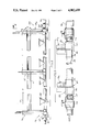
- FIG. 1 is a partial fragmentary perspective view of a poultry house in which a continuous section watering system is illustrated;
- FIG. 2 is an enlarged partial fragmentary side view of the continuous watering system illustrated in FIG. 1;
- FIG. 3 is a partial fragmentary side view of a discrete length watering system showing hangers with integrally formed end couplings in which the ends of the water pipe are securely retained;
- FIG. 4 is an enlarged sectional view taken along line 4--4 in FIG. 3;
- FIG. 5 is an enlarged sectional view taken along the line 5--5 in FIG. 2;
- FIG. 6 is a fragmentary side view taken along line 6-6 in FIG. 5;
- FIG. 7 is an enlarged fragmentary view of detail 7 in FIG. 3 showing a support member blind end as formed in the beam member support portion of the hanger;
- FIG. 8 is an enlarged fragmentary perspective view of a suspension means attachment portion of a hanger illustrating a suspension horn, suspension means bore, and anti-roost insulating bore;
- FIG. 9 is an enlarged partial fragmentary view of water controlling hardware coupled to threaded nipples of end hangers.
- FIG. 1 provides a partial fragmentary perspective view of a poultry house in which a continuous watering system 12 is illustrated.
- the watering system 12 is comprised of hanger means or hanger members 14 which hold and secure a support member or beam 16 preferably, although not necessarily, formed from steel, adding structural support to the watering system 12, and a water pipe 18 preferably formed from plastic to which is attached to a bottom end or portion 20 of the hanger members 14.
- Suspension means in the form of flexible element 24 such as cords or cables are connected to top ends 22 of the hanger members 14, to hold the continuous watering system 12 a distance above the floor of the poultry house.
- the hanger members 14 are spaced periodically along the length of the watering system 12 to provide secure support for the supporting member 16 and the water pipe 18.
- FIG. 2 shows a source end 26 and a terminal end 28 as well as hanger members 14 periodically spaced over the length of the watering system 12.
- the top end 22 of each hanger member 14 has formed thereon a suspension means attaching portion 30 for securing the hanger 14 to suspension means 24 which is secured to a suspension means anchor 32 such as an eye bolt connected to an overhead support member 34.
- suspension means anchor 32 such as an eye bolt connected to an overhead support member 34.
- the suspension means 24 is securable directly to the overhead support member 34 without the suspension means anchor 32.
- each hanger member 14 Located at the bottom end 20 of each hanger member 14 is a pipe supporting portion 36 which securely retains the water pipe 18 to the hanger member 14.
- the cross section of the pipe supporting portion 36 is a non-continuous circular shape which cooperatively mates with the shape of the water pipe 18 retained therein.
- the water pipe 18 is snapped into the pipe supporting portion 36 through the open section 37 (better illustrated in FIG. 5 and described herein below).
- a support member bore 38 formed through the hanger member 14.
- the support member bore 38 securely retains the support member 16 thereby providing structural support for the watering system 12.
- an anti-roost wire 40 Positioned between the top portion 22 of the hanger member 14 and the support member 16 is an anti-roost wire 40 which is suspended between the hanger members 14 to deter animals from stepping or roosting on the support member 16 or the water pipe 18 and attached drinking cups 42.
- the cups 42 include water controlling valves of known construction, for example, such as shown in U.S. Pat. No.4,282,831 to Nilsen.
- the continuous watering system 12 as shown in FIGS. 1 and 2 is assembled using the hanger member 14 approximately every four feet and attachment to the suspension means 24, such as a cord or cable, every eight feet. Also, every other hanger member 14, preferably although not necessarily, the hanger member 14 attached to the suspension means 24, is suitably adhesively connected between the inside surface of the pipe supporting portion 36 and the corresponding contacting portion of the water pipe 18. These periodic adhesive connections between the hanger members 14 and the water pipe 18 prevent the pipe 18 from rotating thereby maintaining the drinking cups 42 in a servicable accessible position.
- a support end hanger member 44 is mounted to the source end 26 and the terminal end 28 of the continuous length watering system.
- the support end hanger member 44 does not provide attachment of the hanger member 44 to the water pipe 18.
- the continuous waterer system may extend for the length of a poultry house and may be up to several hundred feet long. In long systems the differential between the thermal expansion and contraction of the support 16 and pipe 18 can be substantial. The absence of the pipe supporting portion 36 on the support end hangers 44 accommodates the different coefficients of thermal expansion of the support member 16 and water pipe 18.
- Shorter configurations of the watering system are assembled in substantially the same manner as the continuous watering system illustrated in FIG. 1.
- hanger members 14a at the ends of the watering system section preferably are provided with integrally formed end hanger water pipe couplings 48.
- the end hanger water pipe couplings or end couplings 48, as shown on the ends of the watering system section of FIG. 3, are illustrated in greater detail in the fragmentary view illustrated in FIG. 9.
- the end couplings 48 are formed at the bottom end 20 of the hanger members 14a such that a portion of the pipe supporting portion 36 is formed to completely surround the pipe 18 to provide a pipe enclosing portion 50 into which the pipe 18 is inserted to couple the pipe to the end coupling 48.
- an appropriate adhesive is used between the outside of the water pipe 18 and the inside of the pipe enclosing portion 50 of the end coupling 48.
- the end hanger source pipe coupling 48 is also integrally formed with a threaded nipple end 52, which permits attachment of water control hardware such as a control valve 54 and/or a spigot 56.
- FIG. 7 illustrates the construction of a blind end or socket 57 with a closed end wall 59 formed in the hanger 14a.
- the socket 57 captively retains the support member 16 to prevent the support member 16 from accidentally becoming dislodged from the watering system.
- the end hangers 44 of the embodiment shown in FIGS. 1 and 2 also have sockets 57 with closed end walls 59 for retaining the support member 16.
- the pipe enclosing portion 50 of the end coupling 48 completely encloses the end of the water pipe 18. Water passes through or is terminated at the end coupling 48 via the water control hardware 54, 56 attached to the threaded nipple 52.
- the hanger 14 comprises a generally vertically oriented beam member 58 comprising crossed flanges or webs 61 and 63 which are integrally formed with the previously mentioned top end 22, suspension means attachment portion 30, pipe supporting portion 36, and the support means receiving sleeve or support member bore 38.
- the support member sleeve or bore 38 is shown retaining a support member 16, having a generally reversed sigma shape, between upper and lower bearing surfaces 60, 62.
- the support member bore 38 is formed to accommodate either the reverse sigma shaped support member 16 as shown or a tubular support member.
- the support member sleeve 38 may be formed to accommodate a variety of appropriate support member cross-sections without departing from the scope of the invention.
- the internal surface of the support member bore 38 is a bearing surface 64, 60, 62 to facilitate relative sliding of the support member 16 retained within the support member bore 38.
- a wire insulating bore 66 is integrally formed with the hanger beam 58 between the top end 20 and the support member 16 a specified distance above the support member 16 for guiding and retaining anti-roost wire 40 between the hanger members 14 over the length of the watering system 12.
- Electrified anti-roost wire 40 is suspended between the hangers 14 of the watering system 12 to deter animals from stepping or roosting on the support member 16 and the water pipe 18. Since the material used to integrally form the insulating bore 66 in hanger member 14 is preferably a non-conductive material such as ABS PVC or other suitable plastic, a separate insulator between the hanger member 14 and the wire bore 66 is obviated.
- the pipe supporting portion 36 has a generally downwardly facing C-shaped configuration and is formed to cooperatively mate with the cross-sectional shape of the water pipe 18 while permitting the pipe 18 to be inserted into the pipe supporting portion 36 in a snap fit or press-in fashion.
- the water pipe 18 is snapped into the pipe supporting portion 36 by urging the pipe 18 past the open section 37.
- the insertion force applied to the pipe 18 flexes the edge portions 67 slightly to permit insertion of the pipe 18 whereupon the edge portions 67 flex back to their "as formed" shape to retain the water pipe 18.
- an appropriate amount of a suitable adhesive is applied between the outer surface of the water pipe 18 and the inner surface of the pipe supporting portion 36 to prevent the water pipe 18 from rotating while held within the pipe supporting portion 36.
- adhesive should only be applied where necessary to prevent rotation of the water pipe 18 within the pipe supporting portion 36 thereby accommodating the expansion and contraction of the water pipe 18 retained within the pipe supporting portion 36.
- the suspension means attaching portion 30 is integrally formed on the top end 22 of the hanger means 14.
- the suspension means 24 used with the present invention is a flexible cord or other relatively flexible material such as an appropriate size, suitably strong cable.
- the suspension means attaching portion 30 comprises a suspension horn 68 integrally formed on the top end 22 of the hanger means 14.
- a top notch 70 and a lower side notch 72 are formed on the suspension horn 68 of the point which the suspension horn 68 is integrally formed with the hanger member 14.
- a bore 74 is formed beneath to notch 70 and laterally inwardly of the notch 72.
- the suspension means 24 is threaded through the suspension means bore 74 and wrapped around the suspension horn 68 to provide a purchase to adjustably secure the flexible cord 24 to the suspension means attaching portion 30.
- the flexible cord 24 is threaded through the suspension means bore 74, up along a first side of the suspension horn 68 and over and into the top notch 70, down along a second side of the suspension horn 68 and under and into the lower notch 72, back up along the first side of the suspension horn 68 and under the flexible cord 24 positioned through the suspension means bore 74 and over and in the top notch 70, a trailing end 76 of the flexible cord 24 is securely attached to the overhead support 34 and a free end 78 being accessible to elevationally adjust the watering system 12.
- the downward force exerted on the trailing end 76 securely grips the free end 78 which is threaded under a looped portion 79 of the flexible cord 24.
- the relatively thin cross-section of the beam 58 at the top portion 22 of the hanger member 14 promotes hanging of the hanger member 14, suspended from the suspension means 24 in the manner described above, in a generally vertically oriented position.
- the hanger member and all of its constituent portions is a single piece integrally formed of an appropriate plastic such as ABS or PVC.
- the hanger member 14 permits the assembly of a water system without fasteners or tools by providing slide through, snap-on and wrap around attachments of the suspension means 24, anti-roost wire 40, support member 16, and the water pipe 18. Therefore, the watering system described hereinabove provides a simplified, economical and efficient hanger member 14 for the assembly of a watering system.
Abstract
Description
Claims (18)
Priority Applications (1)
| Application Number | Priority Date | Filing Date | Title |
|---|---|---|---|
| US07/375,150 US4982699A (en) | 1989-06-30 | 1989-06-30 | Floor waterer hanger |
Applications Claiming Priority (1)
| Application Number | Priority Date | Filing Date | Title |
|---|---|---|---|
| US07/375,150 US4982699A (en) | 1989-06-30 | 1989-06-30 | Floor waterer hanger |
Publications (1)
| Publication Number | Publication Date |
|---|---|
| US4982699A true US4982699A (en) | 1991-01-08 |
Family
ID=23479703
Family Applications (1)
| Application Number | Title | Priority Date | Filing Date |
|---|---|---|---|
| US07/375,150 Expired - Fee Related US4982699A (en) | 1989-06-30 | 1989-06-30 | Floor waterer hanger |
Country Status (1)
| Country | Link |
|---|---|
| US (1) | US4982699A (en) |
Cited By (6)
| Publication number | Priority date | Publication date | Assignee | Title |
|---|---|---|---|---|
| US5062391A (en) * | 1991-01-29 | 1991-11-05 | Avtron, Inc. | Bracket filler for animal watering device |
| US5178079A (en) * | 1992-01-22 | 1993-01-12 | Ziggity Systems, Inc. | Extruded pipe watering system |
| US5184570A (en) * | 1992-01-22 | 1993-02-09 | Ziggity Systems, Inc | Component watering system |
| US5284110A (en) * | 1991-08-20 | 1994-02-08 | Avtron, Inc. | Bracket connector for a water supply system |
| US5857429A (en) * | 1995-12-20 | 1999-01-12 | Hostetler; Eldon | Poultry watering system |
| US6439159B1 (en) * | 1999-12-27 | 2002-08-27 | James R. Rizzo | Fluid dripper for birds |
Citations (3)
| Publication number | Priority date | Publication date | Assignee | Title |
|---|---|---|---|---|
| US4724797A (en) * | 1985-09-06 | 1988-02-16 | Val Products, Inc. | Height-adjustable watering systems for poultry, small animals and the like |
| US4753196A (en) * | 1986-08-06 | 1988-06-28 | Agri Manufacturing Corp. | Animal watering apparatus and method |
| US4794881A (en) * | 1986-11-20 | 1989-01-03 | Monoflo International, Inc. | Poultry watering system with float box and elongated line |
-
1989
- 1989-06-30 US US07/375,150 patent/US4982699A/en not_active Expired - Fee Related
Patent Citations (3)
| Publication number | Priority date | Publication date | Assignee | Title |
|---|---|---|---|---|
| US4724797A (en) * | 1985-09-06 | 1988-02-16 | Val Products, Inc. | Height-adjustable watering systems for poultry, small animals and the like |
| US4753196A (en) * | 1986-08-06 | 1988-06-28 | Agri Manufacturing Corp. | Animal watering apparatus and method |
| US4794881A (en) * | 1986-11-20 | 1989-01-03 | Monoflo International, Inc. | Poultry watering system with float box and elongated line |
Cited By (7)
| Publication number | Priority date | Publication date | Assignee | Title |
|---|---|---|---|---|
| US5062391A (en) * | 1991-01-29 | 1991-11-05 | Avtron, Inc. | Bracket filler for animal watering device |
| US5284110A (en) * | 1991-08-20 | 1994-02-08 | Avtron, Inc. | Bracket connector for a water supply system |
| US5178079A (en) * | 1992-01-22 | 1993-01-12 | Ziggity Systems, Inc. | Extruded pipe watering system |
| US5184570A (en) * | 1992-01-22 | 1993-02-09 | Ziggity Systems, Inc | Component watering system |
| US5857429A (en) * | 1995-12-20 | 1999-01-12 | Hostetler; Eldon | Poultry watering system |
| US6439159B1 (en) * | 1999-12-27 | 2002-08-27 | James R. Rizzo | Fluid dripper for birds |
| US6578519B2 (en) * | 1999-12-27 | 2003-06-17 | James R. Rizzo | Fluid dripper for birds |
Similar Documents
| Publication | Publication Date | Title |
|---|---|---|
| US4884528A (en) | Water pipe bracket and clip for poultry, small animals and the like watering system | |
| US4669422A (en) | Height-adjustable watering systems for poultry, small animals and the like | |
| US4821988A (en) | Catheter bag holder | |
| US5293835A (en) | Wild bird feeding station with a cluster of bird feeders and baffles which prevent squirrels from reaching the feeders | |
| US5941193A (en) | Adjustable poultry feeder assembly | |
| US4724797A (en) | Height-adjustable watering systems for poultry, small animals and the like | |
| US5284110A (en) | Bracket connector for a water supply system | |
| US4982699A (en) | Floor waterer hanger | |
| US5184570A (en) | Component watering system | |
| WO2005072326A2 (en) | Animal watering system with keyed components | |
| US5230302A (en) | Watering system for poultry, small animals and the like | |
| US4753196A (en) | Animal watering apparatus and method | |
| US4794881A (en) | Poultry watering system with float box and elongated line | |
| US5282440A (en) | Extruded pipe watering system | |
| US5097798A (en) | Fowl watering system | |
| US5048462A (en) | Hanger for water supply system and method of installation | |
| US5601263A (en) | Tree-mounted spray apparatus and method | |
| US4267800A (en) | Suspended watering system for poultry house | |
| US5857429A (en) | Poultry watering system | |
| AU609115B2 (en) | Suspension-type water supply system for poultry | |
| US3389689A (en) | Poultry feeder and suspended unit support | |
| US5245950A (en) | Poultry watering system | |
| US6085691A (en) | Formed treat support | |
| US4341182A (en) | Animal watering apparatus | |
| US6698964B2 (en) | Variably configurable cattle stall connection |
Legal Events
| Date | Code | Title | Description |
|---|---|---|---|
| AS | Assignment |
Owner name: CTB, INC., P.O. BOX 2000, MILFORD, INDIANA Free format text: ASSIGNMENT OF ASSIGNORS INTEREST.;ASSIGNOR:MOMONT, TIMOTHY W.;REEL/FRAME:005145/0410 Effective date: 19890628 |
|
| FEPP | Fee payment procedure |
Free format text: PAYOR NUMBER ASSIGNED (ORIGINAL EVENT CODE: ASPN); ENTITY STATUS OF PATENT OWNER: LARGE ENTITY |
|
| FPAY | Fee payment |
Year of fee payment: 4 |
|
| AS | Assignment |
Owner name: SOCIETY NATIONAL BANK, OHIO Free format text: COLLATERAL ASSIGNMENT & SECURITY AGREEMENT;ASSIGNOR:CTB, INC.;REEL/FRAME:007795/0681 Effective date: 19960104 |
|
| AS | Assignment |
Owner name: CTB, INC., INDIANA Free format text: RELEASE AND ASSIGNMENT OF PATENTS;ASSIGNOR:KEYBANK NATIONAL ASSOCIATION (FORMERLY KNOWN AS, SOCIETY NATIONAL BANK), AS AGENT;REEL/FRAME:008907/0257 Effective date: 19970902 |
|
| FPAY | Fee payment |
Year of fee payment: 8 |
|
| AS | Assignment |
Owner name: CTB IP, INC., DELAWARE Free format text: ASSIGNMENT OF ASSIGNORS INTEREST;ASSIGNOR:CTB, INC.;REEL/FRAME:012463/0254 Effective date: 20011001 |
|
| REMI | Maintenance fee reminder mailed | ||
| LAPS | Lapse for failure to pay maintenance fees | ||
| STCH | Information on status: patent discontinuation |
Free format text: PATENT EXPIRED DUE TO NONPAYMENT OF MAINTENANCE FEES UNDER 37 CFR 1.362 |
|
| FP | Lapsed due to failure to pay maintenance fee |
Effective date: 20030108 |