US4982705A - Cam pulley and cylinder head arrangement for an overhead cam engine - Google Patents
Cam pulley and cylinder head arrangement for an overhead cam engine Download PDFInfo
- Publication number
- US4982705A US4982705A US07/483,063 US48306390A US4982705A US 4982705 A US4982705 A US 4982705A US 48306390 A US48306390 A US 48306390A US 4982705 A US4982705 A US 4982705A
- Authority
- US
- United States
- Prior art keywords
- cylinder head
- crankcase
- camshaft
- air
- crankshaft
- Prior art date
- Legal status (The legal status is an assumption and is not a legal conclusion. Google has not performed a legal analysis and makes no representation as to the accuracy of the status listed.)
- Expired - Lifetime
Links
Images

Classifications
-
- F—MECHANICAL ENGINEERING; LIGHTING; HEATING; WEAPONS; BLASTING
- F02—COMBUSTION ENGINES; HOT-GAS OR COMBUSTION-PRODUCT ENGINE PLANTS
- F02B—INTERNAL-COMBUSTION PISTON ENGINES; COMBUSTION ENGINES IN GENERAL
- F02B63/00—Adaptations of engines for driving pumps, hand-held tools or electric generators; Portable combinations of engines with engine-driven devices
- F02B63/02—Adaptations of engines for driving pumps, hand-held tools or electric generators; Portable combinations of engines with engine-driven devices for hand-held tools
-
- F—MECHANICAL ENGINEERING; LIGHTING; HEATING; WEAPONS; BLASTING
- F01—MACHINES OR ENGINES IN GENERAL; ENGINE PLANTS IN GENERAL; STEAM ENGINES
- F01P—COOLING OF MACHINES OR ENGINES IN GENERAL; COOLING OF INTERNAL-COMBUSTION ENGINES
- F01P5/00—Pumping cooling-air or liquid coolants
- F01P5/02—Pumping cooling-air; Arrangements of cooling-air pumps, e.g. fans or blowers
- F01P5/06—Guiding or ducting air to, or from, ducted fans
-
- F—MECHANICAL ENGINEERING; LIGHTING; HEATING; WEAPONS; BLASTING
- F02—COMBUSTION ENGINES; HOT-GAS OR COMBUSTION-PRODUCT ENGINE PLANTS
- F02B—INTERNAL-COMBUSTION PISTON ENGINES; COMBUSTION ENGINES IN GENERAL
- F02B75/00—Other engines
- F02B75/007—Other engines having vertical crankshafts
-
- F—MECHANICAL ENGINEERING; LIGHTING; HEATING; WEAPONS; BLASTING
- F01—MACHINES OR ENGINES IN GENERAL; ENGINE PLANTS IN GENERAL; STEAM ENGINES
- F01P—COOLING OF MACHINES OR ENGINES IN GENERAL; COOLING OF INTERNAL-COMBUSTION ENGINES
- F01P1/00—Air cooling
- F01P1/02—Arrangements for cooling cylinders or cylinder heads, e.g. ducting cooling-air from its pressure source to cylinders or along cylinders
-
- F—MECHANICAL ENGINEERING; LIGHTING; HEATING; WEAPONS; BLASTING
- F02—COMBUSTION ENGINES; HOT-GAS OR COMBUSTION-PRODUCT ENGINE PLANTS
- F02B—INTERNAL-COMBUSTION PISTON ENGINES; COMBUSTION ENGINES IN GENERAL
- F02B75/00—Other engines
- F02B75/02—Engines characterised by their cycles, e.g. six-stroke
- F02B2075/022—Engines characterised by their cycles, e.g. six-stroke having less than six strokes per cycle
- F02B2075/027—Engines characterised by their cycles, e.g. six-stroke having less than six strokes per cycle four
-
- F—MECHANICAL ENGINEERING; LIGHTING; HEATING; WEAPONS; BLASTING
- F02—COMBUSTION ENGINES; HOT-GAS OR COMBUSTION-PRODUCT ENGINE PLANTS
- F02B—INTERNAL-COMBUSTION PISTON ENGINES; COMBUSTION ENGINES IN GENERAL
- F02B2275/00—Other engines, components or details, not provided for in other groups of this subclass
- F02B2275/20—SOHC [Single overhead camshaft]
Definitions
- the present invention relates generally to overhead cam air-cooled internal combustion engines, and more particularly to such engines wherein the camshaft is driven by an external timing belt and cam pulley.
- Air-cooled internal combustion engines often employ a combination fan/flywheel mounted directly on the crankshaft externally of the crankcase to supply a flow of cooling air over the engine. Since the flywheel is located near the crankcase rather than near the cylinder and cylinder head, which are the portions of the engine most in need of cooling, a blower housing or other ducting is often used to direct the flow of air from the fan/flywheel toward and over the cylinder and cylinder head. This scheme works well in L-head or overhead valve type engines where the valve actuating mechanism is enclosed within the engine castings, since the exteriors of the cylinder and the cylinder head are unobstructed and covered with cooling fins.
- a cam pulley is normally located on an extension of the camshaft externally of the cylinder head, and tends to obstruct the flow of air over the cylinder and cylinder head. This problem cannot be alleviated to a sufficient degree by reducing the diameter of the cam pulley, since four-cycle internal combustion engines require a 2:1 speed reduction of the camshaft relative to the crankshaft, which necessitates the cam pulley being twice as large as the drive pulley.
- the present invention in accordance with one embodiment thereof, involves an air-cooled internal combustion engine of the overhead cam type wherein the camshaft is driven by an external cam pulley connected to a drive pulley by a positive engagement timing belt or chain.
- the cam pulley is provided with integral fan blades for causing air to flow through the cam pulley upon rotation of the cam pulley during engine operation.
- the blades are oriented to cause air to flow toward and over the cylinder and cylinder head, thereby overcoming the air flow blocking effect that the cam pulley would otherwise have.
- the cylinder head includes an air passageway therethrough disposed substantially parallel to the camshaft and located between the intake and exhaust valves and between the camshaft and the cylinder.
- the air passageway increases the cooling surface area of the cylinder head, especially in the immediate proximity of the valves and combustion chamber. The passage of cooling air to the side of the cylinder head opposite the cam pulley is also facilitated.
- Another aspect of the present invention involves the combined cooling effect of a combination fan/flywheel mounted on the crankshaft, a cam pulley configured as a fan, and a blower housing overlying both such that air is drawn in axially by the fan/flywheel, directed longitudinally of the cylinder by the blower housing, and then drawn axially by the fan/cam-pulley and directed particularly over the cylinder head.
- the present invention includes an air-cooled internal combustion engine having a crankcase, a crankshaft disposed within the crankcase and extending externally thereof, and a cylinder extending from the crankcase and having a piston mounted for reciprocation therein and connected to the crankshaft.
- a cylinder head is connected to the cylinder and includes an overhead camshaft disposed therein.
- the camshaft extends externally of the cylinder head.
- a drive pulley is mounted to the crankshaft externally of the crankcase, and a cam pulley is mounted to the camshaft externally of the cylinder head.
- the cam pulley includes a plurality of fan blades for directing air axially toward the cylinder head upon rotation of the cam pulley.
- Drive means positively engages the drive pulley and the cam pulley for transmitting rotary motion therebetween.
- the present invention further includes a cylinder head having an intake valve, an exhaust valve, and an air passageway extending therethrough substantially parallel to the camshaft, the air passage being located between the intake and exhaust valves and between the camshaft and the cylinder.
- FIG. 1 is a vertical section view of an internal combustion engine in accordance with the present invention, taken in the plane defined by the axis of the crankshaft and the axis of the cylinder.
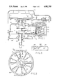
- FIG. 2 is top view of the cam pulley of the engine of FIG. 1, taken along line 2--2 of FIG. 1 and viewed in the direction of the arrows.
- FIG. 3 is a partial section view of the cam pulley of FIG. 2, taken along line 3--3 of FIG. 2 and viewed in the direction of the arrows.
- FIG. 4 is a horizontal section view of an alternative embodiment of a cylinder head useful in combination with the engine of FIG. 1.
- FIG. 5 is a top view of the alternative cylinder head of FIG. 4.
- Engine 10 includes a crankcase 12 which is divided along separation line 14 into upper crankcase housing 16 and lower crankcase housing 18.
- Upper crankcase housing 16 includes upper crankshaft bearing journal 20 and upper crankshaft seal 22.
- piston 25, Disposed for horizontal reciprocation within cylinder 24 is piston 25, which is linked to crankshaft 36 via connecting rod 27.
- Lower crankcase housing 18 provides a mounting base 28 for engine 10 and also provides a lubrication oil sump 30.
- Lower crankcase housing 18 includes lower crankcase bearing journal 32 and lower crankshaft seal 34.
- crankshaft 36 having upper shaft portion 38 situated within upper crankshaft journal 20 and having lower shaft portion 40 situated within lower crankshaft journal 32.
- Lower extension 42 of lower shaft portion 40 provides a drive shaft stub for power take off from engine 10 to be connected to a lawnmower blade or other element.
- Upper extension 44 of upper shaft portion 38 provides a drive shaft stub for driving combination fan/flywheel 46, which is attached thereto for rotation therewith. Also attached to extension 44 for rotation therewith is drive pulley 48 which will be explained further below.
- cylinder head 50 is attached conventionally via bolts (not shown) to the top (with respect to the direction of piston movement) of cylinder 24.
- Overhead camshaft 52 is journalled for rotation within cylinder head 50 and is oriented vertically and parallel to crankshaft 36. Integral cam lobes 54 and 56 on camshaft 52 engage valve operators 58 and 60 which in turn cause reciprocation of intake and exhaust valves 62 and 64.
- Camshaft 52 includes extension 66 which extends upwardly and exteriorly of cylinder head 50. Mounted to extension 66 for rotation therewith is cam pulley 68 which is mounted in the same horizontal plane as drive pulley 48.
- Drive pulley 48 and cam pulley 68 are similarly notched to ensure positive registration of timing belt 70 with each pulley, thereby maintaining over time the desired angular relationship between crankshaft 36 and camshaft 66.
- Cam pulley 68 has a diameter which is twice that of drive pulley 48, which results in camshaft 52 rotating at one-half the rate of rotation of crankshaft 36. This 2:1 speed relationship is necessitated by the four-cycle nature of engine 10.
- Cooling of engine 10 is accomplished by the forced flow of air thereover, provided primarily by combination fan/flywheel 46, which is of conventional design.
- Fan/flywheel 46 operates predominantly as a centrifugal type blower, wherein air is drawn in axially toward crankshaft 36 and expelled radially.
- Blower cover 72 which overlies fan/flywheel 46, cylinder 24 and cylinder head 50, directs the radial air flow downwardly and over cylinder 24 and cylinder head 50.
- cam pulley 68 Because of the relatively large diameter of cam pulley 68, necessitated by the required 2:1 speed reduction from drive pulley 48, air flow over cylinder head 50 would be largely blocked by cam pulley 68 if it were of conventional design. A solid cam pulley would totally prevent air flow therethrough, resulting in a substantial reduction in the cooling efficacy of fan/flywheel 46. It has been found that a conventional sprocketed or spoked cam pulley blocks the flow of air over cylinder head 50 nearly as greatly as a solid pulley. This is believed to be the result of such a pulley acting essentially like a centrifugal blower, causing axial air flow toward the camshaft generated by fan/flywheel 46 to be redirected around the cam pulley instead of proceeding through it.
- the present invention permits the use of an external cam pulley driven by an external drive pulley on the crankshaft without impeding air cooling of the cylinder and cylinder head over which the cam pulley lies. This is accomplished by configuring the cam pulley as shown in FIGS. 2 and 3.
- Cam pulley 68 includes a hub 74 which circumscribes and mounts on extension 66 of camshaft 52. Hub 74 is secured to shaft 66 by conventional keying or splining to ensure that cam pulley 68 does not slip with respect to camshaft 52.
- An integral annular inner ring portion 76 is attached to hub 74 in a plane perpendicular to camshaft extension 66, and an integral annular outer ring portion 78 defining the outer diameter of cam pulley 68 is disposed in the same plane as inner ring 76.
- Connecting inner ring 76 and outer ring 78 in their common plane is a plurality of interspersed radial spokes 82.
- Fan blades 84 are inclined with respect to the plane of pulley 68 in a direction perpendicular to the radial spoke 82 from which fan blades 84 extend.
- cam pulley 68 (as viewed from above) results in cam pulley 68 acting as a fan to accelerate air axially toward cylinder head 50, thereby overcoming the air blocking effect of the cam pulley and in fact positively contributing to the flow of air over cylinder head 50.
- Portions 76, 82, 84 and 78 of pulley 68 may be integral and may be made of cast aluminum, molded plastic or any other suitable material.
- a preferred material for pulley 68 is nylon cast around a metal hub.
- Cylinder head 50' includes intake port 86 and exhaust port 88 located opposite one another on either side of cylinder head 50'. The flow of gases into and out of the combustion chamber is predominantly in the horizontal direction, and perpendicular to the axis of the camshaft 52'.
- Intake valve 62' and exhaust valve 64' are offset from one another in the axial direction of camshaft 52', and are inclined toward one another in the horizontal plane in the direction toward combustion chamber 90.
- Valves 62' and 64' reciprocate in valve guide bores 92 and 94, respectively, and are biased toward their respective valve seats 96 and 98 by valve springs 100 and 102 which bear with their bottom ends on cylinder head 50' and with their top ends on valve spring retainers 104 and 106, which are connected to the upper ends of the valve stems of valves 62' and 64'.
- a pair of rocker arms 108 and 110 are pivotally mounted on a rocker shaft 112 disposed in cylinder head 50' parallel to camshaft 52'. Cam follower surfaces 114 and 116 of rocker arms 108 and 110 engage the respective intake and exhaust cam lobes 54' and 56'.
- a removable cover 118 encloses the top end of cylinder head 50'.
- cylinder head 50' is constructed with vertically oriented cooling fins 120 cast integrally therewith, and with a through opening 122 which provides a generally vertical passageway parallel to the axis of the camshaft for the passage of air through the cylinder head.
- Opening 122 is situated between the intake and exhaust valves 92 and 94, and below the camshaft 52', and serves to increase the total surface area of cylinder head 52' as well as to provide an additional path for cooling air to reach the bottom side of cylinder head 52'.
- opening 122 permits air to flow immediately adjacent the top of combustion chamber 90 and next to the valve heads.
Abstract
Description
Claims (13)
Priority Applications (2)
| Application Number | Priority Date | Filing Date | Title |
|---|---|---|---|
| US07/483,063 US4982705A (en) | 1990-02-21 | 1990-02-21 | Cam pulley and cylinder head arrangement for an overhead cam engine |
| CA002026952A CA2026952A1 (en) | 1990-02-21 | 1990-10-04 | Cooling means for overhead cam engine |
Applications Claiming Priority (1)
| Application Number | Priority Date | Filing Date | Title |
|---|---|---|---|
| US07/483,063 US4982705A (en) | 1990-02-21 | 1990-02-21 | Cam pulley and cylinder head arrangement for an overhead cam engine |
Publications (1)
| Publication Number | Publication Date |
|---|---|
| US4982705A true US4982705A (en) | 1991-01-08 |
Family
ID=23918491
Family Applications (1)
| Application Number | Title | Priority Date | Filing Date |
|---|---|---|---|
| US07/483,063 Expired - Lifetime US4982705A (en) | 1990-02-21 | 1990-02-21 | Cam pulley and cylinder head arrangement for an overhead cam engine |
Country Status (2)
| Country | Link |
|---|---|
| US (1) | US4982705A (en) |
| CA (1) | CA2026952A1 (en) |
Cited By (32)
| Publication number | Priority date | Publication date | Assignee | Title |
|---|---|---|---|---|
| US5199388A (en) * | 1992-07-02 | 1993-04-06 | Outboard Marine Corporation | Axial fan flywheel |
| US5245954A (en) * | 1992-07-02 | 1993-09-21 | Outboard Marine Corporation | Axial fan flywheel |
| US5755194A (en) * | 1995-07-06 | 1998-05-26 | Tecumseh Products Company | Overhead cam engine with dry sump lubrication system |
| US6223713B1 (en) | 1996-07-01 | 2001-05-01 | Tecumseh Products Company | Overhead cam engine with cast-in valve seats |
| US6813971B2 (en) * | 2000-05-25 | 2004-11-09 | Enplas Corporation | Molded gear |
| US20050186091A1 (en) * | 2004-02-09 | 2005-08-25 | Ghassem Zarbi | Cooling fan mechanism for a motor-driven pressure washer |
| US20050218178A1 (en) * | 2004-04-02 | 2005-10-06 | Alan Berry | Lock-out for activation arm mechanism in a power tool |
| US20050218186A1 (en) * | 2004-04-02 | 2005-10-06 | Michael Forster | Method for sizing a motor for a power tool |
| US20050218174A1 (en) * | 2004-04-02 | 2005-10-06 | Kenney James J | Activation arm configuration for a power tool |
| US20050218181A1 (en) * | 2004-04-02 | 2005-10-06 | Paul Gross | Upper bumper configuration for a power tool |
| US20050218183A1 (en) * | 2004-04-02 | 2005-10-06 | Alan Berry | Driver configuration for a power tool |
| US20050217873A1 (en) * | 2004-04-02 | 2005-10-06 | Paul Gross | Solenoid positioning methodology |
| US20050218184A1 (en) * | 2004-04-02 | 2005-10-06 | Buck John E | Structural backbone / motor mount for a power tool |
| US20050217876A1 (en) * | 2004-04-02 | 2005-10-06 | Kenney James J | Activation arm assembly method |
| US20050218180A1 (en) * | 2004-04-02 | 2005-10-06 | Paul Gross | Lower bumper configuration for a power tool |
| US20050218182A1 (en) * | 2004-04-02 | 2005-10-06 | Alan Berry | Return cord assembly for a power tool |
| US20050217416A1 (en) * | 2004-04-02 | 2005-10-06 | Alan Berry | Overmolded article and method for forming same |
| US20050218185A1 (en) * | 2004-04-02 | 2005-10-06 | Kenney James J | Cam and clutch configuration for a power tool |
| US20050224552A1 (en) * | 2004-04-02 | 2005-10-13 | Alan Berry | Flywheel configuration for a power tool |
| US7138595B2 (en) | 2004-04-02 | 2006-11-21 | Black & Decker Inc. | Trigger configuration for a power tool |
| US20070102471A1 (en) * | 2004-04-02 | 2007-05-10 | Gross Paul G | Power take off for cordless nailer |
| US20080238221A1 (en) * | 2007-04-02 | 2008-10-02 | Yamaha Motor Power Products Kabushiki Kaisha | Soundproof type engine generator |
| US20080302852A1 (en) * | 2007-06-11 | 2008-12-11 | Brendel Lee M | Profile lifter for a nailer |
| EP2177658A1 (en) * | 2008-10-14 | 2010-04-21 | BSH Electrodomésticos España, S.A. | Pulley and washing machine with a pulley |
| US20120160194A1 (en) * | 2010-12-24 | 2012-06-28 | Takahiro Yano | Cooling apparatus of engine |
| US20150034345A1 (en) * | 2013-08-01 | 2015-02-05 | Basso Industry Corp. | Electric power tool |
| JP2015151885A (en) * | 2014-02-12 | 2015-08-24 | スズキ株式会社 | Cooling structure of engine |
| US20150322843A1 (en) * | 2014-05-06 | 2015-11-12 | Champion Engine Technology, LLC | Air flow guide for an internal combustion engine |
| CN109372633A (en) * | 2018-12-25 | 2019-02-22 | 苏州帕瓦麦斯动力有限公司 | The inversion small-size double cylinder generating set of high-efficient noise-reducing |
| US10766128B2 (en) * | 2014-07-28 | 2020-09-08 | Black & Decker Inc. | Power tool drive mechanism |
| CN111790211A (en) * | 2019-04-04 | 2020-10-20 | 赛峰飞机发动机公司 | Oil-gas separator transmission gear and related turbine accessory box and turbine |
| US10882172B2 (en) | 2004-04-02 | 2021-01-05 | Black & Decker, Inc. | Powered hand-held fastening tool |
Citations (22)
| Publication number | Priority date | Publication date | Assignee | Title |
|---|---|---|---|---|
| US1270124A (en) * | 1917-01-23 | 1918-06-18 | W H Kendricks | Internal-combustion engine. |
| US1271354A (en) * | 1916-11-15 | 1918-07-02 | Glenn Nus | Valve mechanism for internal-combustion engines. |
| US1357135A (en) * | 1919-09-09 | 1920-10-26 | Arthur L Anderson | Internal-combustion motor |
| US1464357A (en) * | 1921-06-21 | 1923-08-07 | Fox Motor Car Company | Air-cooling system for engines of motor vehicles |
| US1512546A (en) * | 1922-03-06 | 1924-10-21 | Marathon Electric Mfg Co | Pulley-ventilating means |
| US1673191A (en) * | 1927-11-17 | 1928-06-12 | Bryan Screw Machine Products C | Air compressor and the like |
| US2270990A (en) * | 1940-01-25 | 1942-01-27 | Reconstruction Finance Corp | Engine |
| US2410411A (en) * | 1942-05-19 | 1946-11-05 | Fairchild Engine & Airplane | Engine valve control mechanism |
| US2426438A (en) * | 1944-03-01 | 1947-08-26 | Fairchild Engine & Airplane | Engine cylinder construction |
| US3079902A (en) * | 1958-11-15 | 1963-03-05 | Linde Eismasch Ag | Air-cooled cylinder head, in particular for internal combustion engines |
| US3166053A (en) * | 1962-12-03 | 1965-01-19 | Maschf Augsburg Nuernberg Ag | Monobloc air-cooled internal combustion engine cylinder |
| US3598092A (en) * | 1968-09-14 | 1971-08-10 | Honda Motor Co Ltd | Air cooling apparatus for an internal combustion engine of a vehicle |
| US3669082A (en) * | 1969-05-07 | 1972-06-13 | Hatz Motoren | Internal combustion engine having a cooling-air blower |
| JPS5537507A (en) * | 1978-09-07 | 1980-03-15 | Yamaha Motor Co Ltd | Two wheeler provided with overhead cam shaft type 4-cycle engine |
| US4216746A (en) * | 1977-06-07 | 1980-08-12 | Hans List | Cylinder head for an air-cooled internal combustion engine |
| GB2066361A (en) * | 1980-01-02 | 1981-07-08 | Nat Res Dev | Valve timing mechanisms of internal combustion engines |
| US4391231A (en) * | 1980-03-04 | 1983-07-05 | Mitsubishi Jukogyo Kabushiki Kaisha | Cylinder head for air-cooled engines |
| US4493677A (en) * | 1981-12-29 | 1985-01-15 | Honda Motor Co., Ltd. | Belt transmission having circulated air cooling function |
| US4525993A (en) * | 1983-12-27 | 1985-07-02 | Northern Telecom Limited | Twisting machine |
| US4561386A (en) * | 1983-12-20 | 1985-12-31 | Kawasaki Jukogyo Kabushiki Kaisha | Fan housing for engine |
| US4633824A (en) * | 1984-03-30 | 1987-01-06 | Kubota Limited | Cooling means for the squish part of an air cooling overhead valve engine |
| US4635592A (en) * | 1984-03-14 | 1987-01-13 | Bombardier-Rotax Gesellschaft M.B.H. | Valve control for an internal combustion engine |
-
1990
- 1990-02-21 US US07/483,063 patent/US4982705A/en not_active Expired - Lifetime
- 1990-10-04 CA CA002026952A patent/CA2026952A1/en not_active Abandoned
Patent Citations (22)
| Publication number | Priority date | Publication date | Assignee | Title |
|---|---|---|---|---|
| US1271354A (en) * | 1916-11-15 | 1918-07-02 | Glenn Nus | Valve mechanism for internal-combustion engines. |
| US1270124A (en) * | 1917-01-23 | 1918-06-18 | W H Kendricks | Internal-combustion engine. |
| US1357135A (en) * | 1919-09-09 | 1920-10-26 | Arthur L Anderson | Internal-combustion motor |
| US1464357A (en) * | 1921-06-21 | 1923-08-07 | Fox Motor Car Company | Air-cooling system for engines of motor vehicles |
| US1512546A (en) * | 1922-03-06 | 1924-10-21 | Marathon Electric Mfg Co | Pulley-ventilating means |
| US1673191A (en) * | 1927-11-17 | 1928-06-12 | Bryan Screw Machine Products C | Air compressor and the like |
| US2270990A (en) * | 1940-01-25 | 1942-01-27 | Reconstruction Finance Corp | Engine |
| US2410411A (en) * | 1942-05-19 | 1946-11-05 | Fairchild Engine & Airplane | Engine valve control mechanism |
| US2426438A (en) * | 1944-03-01 | 1947-08-26 | Fairchild Engine & Airplane | Engine cylinder construction |
| US3079902A (en) * | 1958-11-15 | 1963-03-05 | Linde Eismasch Ag | Air-cooled cylinder head, in particular for internal combustion engines |
| US3166053A (en) * | 1962-12-03 | 1965-01-19 | Maschf Augsburg Nuernberg Ag | Monobloc air-cooled internal combustion engine cylinder |
| US3598092A (en) * | 1968-09-14 | 1971-08-10 | Honda Motor Co Ltd | Air cooling apparatus for an internal combustion engine of a vehicle |
| US3669082A (en) * | 1969-05-07 | 1972-06-13 | Hatz Motoren | Internal combustion engine having a cooling-air blower |
| US4216746A (en) * | 1977-06-07 | 1980-08-12 | Hans List | Cylinder head for an air-cooled internal combustion engine |
| JPS5537507A (en) * | 1978-09-07 | 1980-03-15 | Yamaha Motor Co Ltd | Two wheeler provided with overhead cam shaft type 4-cycle engine |
| GB2066361A (en) * | 1980-01-02 | 1981-07-08 | Nat Res Dev | Valve timing mechanisms of internal combustion engines |
| US4391231A (en) * | 1980-03-04 | 1983-07-05 | Mitsubishi Jukogyo Kabushiki Kaisha | Cylinder head for air-cooled engines |
| US4493677A (en) * | 1981-12-29 | 1985-01-15 | Honda Motor Co., Ltd. | Belt transmission having circulated air cooling function |
| US4561386A (en) * | 1983-12-20 | 1985-12-31 | Kawasaki Jukogyo Kabushiki Kaisha | Fan housing for engine |
| US4525993A (en) * | 1983-12-27 | 1985-07-02 | Northern Telecom Limited | Twisting machine |
| US4635592A (en) * | 1984-03-14 | 1987-01-13 | Bombardier-Rotax Gesellschaft M.B.H. | Valve control for an internal combustion engine |
| US4633824A (en) * | 1984-03-30 | 1987-01-06 | Kubota Limited | Cooling means for the squish part of an air cooling overhead valve engine |
Cited By (57)
| Publication number | Priority date | Publication date | Assignee | Title |
|---|---|---|---|---|
| US5199388A (en) * | 1992-07-02 | 1993-04-06 | Outboard Marine Corporation | Axial fan flywheel |
| US5245954A (en) * | 1992-07-02 | 1993-09-21 | Outboard Marine Corporation | Axial fan flywheel |
| US5755194A (en) * | 1995-07-06 | 1998-05-26 | Tecumseh Products Company | Overhead cam engine with dry sump lubrication system |
| US5979392A (en) * | 1995-07-06 | 1999-11-09 | Tecumseh Products Company | Overhead cam engine with integral head |
| US5988135A (en) * | 1995-07-06 | 1999-11-23 | Tecumseh Products Company | Overhead vertical camshaft engine with external camshaft drive |
| US6032635A (en) * | 1995-07-06 | 2000-03-07 | Tecumseh Products Company | Overhead cam engine with integral head |
| US6223713B1 (en) | 1996-07-01 | 2001-05-01 | Tecumseh Products Company | Overhead cam engine with cast-in valve seats |
| US6813971B2 (en) * | 2000-05-25 | 2004-11-09 | Enplas Corporation | Molded gear |
| US20050186091A1 (en) * | 2004-02-09 | 2005-08-25 | Ghassem Zarbi | Cooling fan mechanism for a motor-driven pressure washer |
| US8302833B2 (en) | 2004-04-02 | 2012-11-06 | Black & Decker Inc. | Power take off for cordless nailer |
| US7204403B2 (en) | 2004-04-02 | 2007-04-17 | Black & Decker Inc. | Activation arm configuration for a power tool |
| US20050218174A1 (en) * | 2004-04-02 | 2005-10-06 | Kenney James J | Activation arm configuration for a power tool |
| US20050218181A1 (en) * | 2004-04-02 | 2005-10-06 | Paul Gross | Upper bumper configuration for a power tool |
| US20050218183A1 (en) * | 2004-04-02 | 2005-10-06 | Alan Berry | Driver configuration for a power tool |
| US20050217873A1 (en) * | 2004-04-02 | 2005-10-06 | Paul Gross | Solenoid positioning methodology |
| US20050218184A1 (en) * | 2004-04-02 | 2005-10-06 | Buck John E | Structural backbone / motor mount for a power tool |
| US20050217876A1 (en) * | 2004-04-02 | 2005-10-06 | Kenney James J | Activation arm assembly method |
| US20050218180A1 (en) * | 2004-04-02 | 2005-10-06 | Paul Gross | Lower bumper configuration for a power tool |
| US20050218182A1 (en) * | 2004-04-02 | 2005-10-06 | Alan Berry | Return cord assembly for a power tool |
| US20050217416A1 (en) * | 2004-04-02 | 2005-10-06 | Alan Berry | Overmolded article and method for forming same |
| US20050218185A1 (en) * | 2004-04-02 | 2005-10-06 | Kenney James J | Cam and clutch configuration for a power tool |
| US20050224552A1 (en) * | 2004-04-02 | 2005-10-13 | Alan Berry | Flywheel configuration for a power tool |
| US7138595B2 (en) | 2004-04-02 | 2006-11-21 | Black & Decker Inc. | Trigger configuration for a power tool |
| US7165305B2 (en) | 2004-04-02 | 2007-01-23 | Black & Decker Inc. | Activation arm assembly method |
| US8231039B2 (en) | 2004-04-02 | 2012-07-31 | Black & Decker Inc. | Structural backbone/motor mount for a power tool |
| US20070102471A1 (en) * | 2004-04-02 | 2007-05-10 | Gross Paul G | Power take off for cordless nailer |
| US7322506B2 (en) | 2004-04-02 | 2008-01-29 | Black & Decker Inc. | Electric driving tool with driver propelled by flywheel inertia |
| US7331403B2 (en) | 2004-04-02 | 2008-02-19 | Black & Decker Inc. | Lock-out for activation arm mechanism in a power tool |
| US11090791B2 (en) | 2004-04-02 | 2021-08-17 | Black & Decker Inc. | Powered hand-held fastening tool |
| US10882172B2 (en) | 2004-04-02 | 2021-01-05 | Black & Decker, Inc. | Powered hand-held fastening tool |
| US7503401B2 (en) | 2004-04-02 | 2009-03-17 | Black & Decker Inc. | Solenoid positioning methodology |
| US10272554B2 (en) | 2004-04-02 | 2019-04-30 | Black & Decker Inc. | Powered hand-held fastening tool |
| US20050218186A1 (en) * | 2004-04-02 | 2005-10-06 | Michael Forster | Method for sizing a motor for a power tool |
| US7686199B2 (en) | 2004-04-02 | 2010-03-30 | Black & Decker Inc. | Lower bumper configuration for a power tool |
| US9486905B2 (en) | 2004-04-02 | 2016-11-08 | Black & Decker Inc. | Driving tool with controller having microswitch for controlling operation of motor |
| US7726536B2 (en) | 2004-04-02 | 2010-06-01 | Black & Decker Inc. | Upper bumper configuration for a power tool |
| US7789169B2 (en) | 2004-04-02 | 2010-09-07 | Black & Decker Inc. | Driver configuration for a power tool |
| US7975893B2 (en) | 2004-04-02 | 2011-07-12 | Black & Decker Inc. | Return cord assembly for a power tool |
| US8011549B2 (en) | 2004-04-02 | 2011-09-06 | Black & Decker Inc. | Flywheel configuration for a power tool |
| US8123099B2 (en) | 2004-04-02 | 2012-02-28 | Black & Decker Inc. | Cam and clutch configuration for a power tool |
| US20050218178A1 (en) * | 2004-04-02 | 2005-10-06 | Alan Berry | Lock-out for activation arm mechanism in a power tool |
| US7557458B2 (en) * | 2007-04-02 | 2009-07-07 | Yamaha Motor Power Products Kabushiki Kaisha | Soundproof type engine generator |
| US20080238221A1 (en) * | 2007-04-02 | 2008-10-02 | Yamaha Motor Power Products Kabushiki Kaisha | Soundproof type engine generator |
| US7556184B2 (en) | 2007-06-11 | 2009-07-07 | Black & Decker Inc. | Profile lifter for a nailer |
| US20080302852A1 (en) * | 2007-06-11 | 2008-12-11 | Brendel Lee M | Profile lifter for a nailer |
| EP2177658A1 (en) * | 2008-10-14 | 2010-04-21 | BSH Electrodomésticos España, S.A. | Pulley and washing machine with a pulley |
| US8899191B2 (en) * | 2010-12-24 | 2014-12-02 | Kawasaki Jukogyo Kabushiki Kaisha | Cooling apparatus of engine |
| US20120160194A1 (en) * | 2010-12-24 | 2012-06-28 | Takahiro Yano | Cooling apparatus of engine |
| US20150034345A1 (en) * | 2013-08-01 | 2015-02-05 | Basso Industry Corp. | Electric power tool |
| JP2015151885A (en) * | 2014-02-12 | 2015-08-24 | スズキ株式会社 | Cooling structure of engine |
| US9617951B2 (en) * | 2014-05-06 | 2017-04-11 | Champion Engine Technology, LLC | Air flow guide for an internal combustion engine |
| US20150322843A1 (en) * | 2014-05-06 | 2015-11-12 | Champion Engine Technology, LLC | Air flow guide for an internal combustion engine |
| US10766128B2 (en) * | 2014-07-28 | 2020-09-08 | Black & Decker Inc. | Power tool drive mechanism |
| CN109372633A (en) * | 2018-12-25 | 2019-02-22 | 苏州帕瓦麦斯动力有限公司 | The inversion small-size double cylinder generating set of high-efficient noise-reducing |
| CN111790211A (en) * | 2019-04-04 | 2020-10-20 | 赛峰飞机发动机公司 | Oil-gas separator transmission gear and related turbine accessory box and turbine |
| US11433336B2 (en) * | 2019-04-04 | 2022-09-06 | Safran Aircraft Engines | Drive pinion of an air-oil separator of a turbomachine accessory gearbox |
| EP3719283B1 (en) * | 2019-04-04 | 2023-06-07 | Safran Aircraft Engines | Pinion for driving an air/oil separator of an accessories unit of a turbine engine |
Also Published As
| Publication number | Publication date |
|---|---|
| CA2026952A1 (en) | 1991-08-22 |
Similar Documents
| Publication | Publication Date | Title |
|---|---|---|
| US4982705A (en) | Cam pulley and cylinder head arrangement for an overhead cam engine | |
| AU762227B2 (en) | Mid cam engine | |
| US6945215B2 (en) | Multiple-position, operator-carried, four-stroke engine | |
| JP3566087B2 (en) | Four cycle engine | |
| EP1039099B1 (en) | Drive train for overhead cam engine | |
| US6276324B1 (en) | Overhead ring cam engine with angled split housing | |
| US6925970B2 (en) | Air-cooled four-stroke internal combustion engine | |
| KR100528821B1 (en) | V-2 engine | |
| CN1170056C (en) | Hand four stroke engine | |
| JP2005282582A (en) | Four-stroke internal combustion engine | |
| JPH0658198A (en) | Internal combustion engine with integral cylinder head | |
| US6584964B1 (en) | Engine having a centrifugal oil separator | |
| EP1039098B1 (en) | External drive double shaft overhead cam engine (dschc) | |
| US6799548B2 (en) | Bearing case for engine | |
| US7357108B2 (en) | Valve-operating mechanism | |
| JPH0874551A (en) | Breather device in engine | |
| US20020007983A1 (en) | Lubricating system for OHC engine | |
| JP2003239740A (en) | Cooling water pump device for engine | |
| CN1153900C (en) | Seal structure between cylinder cap and end cap in engine | |
| JPH09177528A (en) | Lubricating device for four cycle engine | |
| JP3273330B2 (en) | Motorcycle unit swing engine | |
| JPH032671Y2 (en) | ||
| JP3309187B2 (en) | Motorcycle unit swing engine | |
| JPH0110407Y2 (en) | ||
| JP2002242674A (en) | Cooling fan for general engine |
Legal Events
| Date | Code | Title | Description |
|---|---|---|---|
| AS | Assignment |
Owner name: TECUMSEH PRODUCTS COMPANY, MICHIGAN Free format text: ASSIGNMENT OF ASSIGNORS INTEREST.;ASSIGNOR:HUDSON, ERIC B.;REEL/FRAME:005235/0830 Effective date: 19900216 |
|
| STCF | Information on status: patent grant |
Free format text: PATENTED CASE |
|
| FEPP | Fee payment procedure |
Free format text: PAYOR NUMBER ASSIGNED (ORIGINAL EVENT CODE: ASPN); ENTITY STATUS OF PATENT OWNER: LARGE ENTITY |
|
| FPAY | Fee payment |
Year of fee payment: 4 |
|
| FPAY | Fee payment |
Year of fee payment: 8 |
|
| FPAY | Fee payment |
Year of fee payment: 12 |
|
| AS | Assignment |
Owner name: JPMORGAN CHASE BANK, N.A.,MICHIGAN Free format text: SECURITY AGREEMENT;ASSIGNOR:TECUMSEH PRODUCTS COMPANY;REEL/FRAME:016641/0380 Effective date: 20050930 Owner name: JPMORGAN CHASE BANK, N.A., MICHIGAN Free format text: SECURITY AGREEMENT;ASSIGNOR:TECUMSEH PRODUCTS COMPANY;REEL/FRAME:016641/0380 Effective date: 20050930 |
|
| AS | Assignment |
Owner name: CITICORP USA, INC.,NEW YORK Free format text: SECURITY INTEREST;ASSIGNORS:TECUMSEH PRODUCTS COMPANY;CONVERGENT TECHNOLOGIES INTERNATIONAL, INC.;TECUMSEH TRADING COMPANY;AND OTHERS;REEL/FRAME:017606/0644 Effective date: 20060206 Owner name: CITICORP USA, INC., NEW YORK Free format text: SECURITY INTEREST;ASSIGNORS:TECUMSEH PRODUCTS COMPANY;CONVERGENT TECHNOLOGIES INTERNATIONAL, INC.;TECUMSEH TRADING COMPANY;AND OTHERS;REEL/FRAME:017606/0644 Effective date: 20060206 |
|
| AS | Assignment |
Owner name: TECUMSEH POWER COMPANY, CALIFORNIA Free format text: ASSIGNMENT OF ASSIGNORS INTEREST;ASSIGNOR:TECUMSEH PRODUCTS COMPANY;REEL/FRAME:020196/0612 Effective date: 20071109 |
|
| AS | Assignment |
Owner name: TECUMSEH DO BRASIL USA, LLC, MICHIGAN Free format text: PARTIAL RELEASE OF SECURITY INTEREST;ASSIGNOR:CITICORP NORTH AMERICA, INC.;REEL/FRAME:020417/0052 Effective date: 20080111 Owner name: CONVERGENT TECHNOLOGIES INTERNATIONAL, INC., MICHI Free format text: PARTIAL RELEASE OF SECURITY INTEREST;ASSIGNOR:CITICORP NORTH AMERICA, INC.;REEL/FRAME:020417/0052 Effective date: 20080111 Owner name: EUROMOTOR, INC., MICHIGAN Free format text: PARTIAL RELEASE OF SECURITY INTEREST;ASSIGNOR:CITICORP NORTH AMERICA, INC.;REEL/FRAME:020417/0052 Effective date: 20080111 Owner name: TECUMSEH AUTO, INC., FORMERLY FASCO INDUSTRIES, IN Free format text: PARTIAL RELEASE OF SECURITY INTEREST;ASSIGNOR:CITICORP NORTH AMERICA, INC.;REEL/FRAME:020417/0052 Effective date: 20080111 Owner name: TECUMSEH PRODUCTS COMPANY, MICHIGAN Free format text: PARTIAL RELEASE OF SECURITY INTEREST;ASSIGNOR:CITICORP NORTH AMERICA, INC.;REEL/FRAME:020417/0052 Effective date: 20080111 Owner name: TECUMSEH TRADING COMPANY, MICHIGAN Free format text: PARTIAL RELEASE OF SECURITY INTEREST;ASSIGNOR:CITICORP NORTH AMERICA, INC.;REEL/FRAME:020417/0052 Effective date: 20080111 Owner name: TECUMSEH POWER COMPANY, WISCONSIN Free format text: PARTIAL RELEASE OF SECURITY INTEREST;ASSIGNOR:CITICORP NORTH AMERICA, INC.;REEL/FRAME:020417/0052 Effective date: 20080111 Owner name: VON WEISE GEAR COMPANY, MICHIGAN Free format text: PARTIAL RELEASE OF SECURITY INTEREST;ASSIGNOR:CITICORP NORTH AMERICA, INC.;REEL/FRAME:020417/0052 Effective date: 20080111 Owner name: HAYTON PROPERTY COMPANY, LLC, MICHIGAN Free format text: PARTIAL RELEASE OF SECURITY INTEREST;ASSIGNOR:CITICORP NORTH AMERICA, INC.;REEL/FRAME:020417/0052 Effective date: 20080111 Owner name: M.P. PUMPS, INC., MICHIGAN Free format text: PARTIAL RELEASE OF SECURITY INTEREST;ASSIGNOR:CITICORP NORTH AMERICA, INC.;REEL/FRAME:020417/0052 Effective date: 20080111 Owner name: TECUMSEH COMPRESSOR COMPANY, MICHIGAN Free format text: PARTIAL RELEASE OF SECURITY INTEREST;ASSIGNOR:CITICORP NORTH AMERICA, INC.;REEL/FRAME:020417/0052 Effective date: 20080111 Owner name: EVERGY, INC., MICHIGAN Free format text: PARTIAL RELEASE OF SECURITY INTEREST;ASSIGNOR:CITICORP NORTH AMERICA, INC.;REEL/FRAME:020417/0052 Effective date: 20080111 Owner name: MANUFACTURING DATA SYSTEMS, INC., MICHIGAN Free format text: PARTIAL RELEASE OF SECURITY INTEREST;ASSIGNOR:CITICORP NORTH AMERICA, INC.;REEL/FRAME:020417/0052 Effective date: 20080111 Owner name: TECUMSEH PUMP COMPANY, MICHIGAN Free format text: PARTIAL RELEASE OF SECURITY INTEREST;ASSIGNOR:CITICORP NORTH AMERICA, INC.;REEL/FRAME:020417/0052 Effective date: 20080111 Owner name: TECUMSEH CANADA HOLDING COMPANY, MICHIGAN Free format text: PARTIAL RELEASE OF SECURITY INTEREST;ASSIGNOR:CITICORP NORTH AMERICA, INC.;REEL/FRAME:020417/0052 Effective date: 20080111 Owner name: LITTLE GIANT PUMP COMPANY, OKLAHOMA Free format text: PARTIAL RELEASE OF SECURITY INTEREST;ASSIGNOR:CITICORP NORTH AMERICA, INC.;REEL/FRAME:020417/0052 Effective date: 20080111 |
|
| AS | Assignment |
Owner name: WELLS FARGO FOOTHILL, LLC, CALIFORNIA Free format text: SECURITY AGREEMENT;ASSIGNOR:TECUMSEH POWER COMPANY;REEL/FRAME:020431/0127 Effective date: 20071221 |
|
| AS | Assignment |
Owner name: TECUMSEH PRODUCTS COMPANY, MICHIGAN Free format text: PARTIAL RELEASE OF SECURITY INTEREST;ASSIGNOR:JPMORGAN CHASE BANK, N.A.;REEL/FRAME:020582/0023 Effective date: 20080115 Owner name: VON WEISE GEAR COMPANY, MICHIGAN Free format text: PARTIAL RELEASE OF SECURITY INTEREST;ASSIGNOR:JPMORGAN CHASE BANK, N.A.;REEL/FRAME:020582/0023 Effective date: 20080115 Owner name: DOUGLAS HOLDINGS, INC., MICHIGAN Free format text: PARTIAL RELEASE OF SECURITY INTEREST;ASSIGNOR:JPMORGAN CHASE BANK, N.A.;REEL/FRAME:020582/0023 Effective date: 20080115 Owner name: CONVERGENT TECHNOLOGIES INTERNATIONAL, INC., MICHI Free format text: PARTIAL RELEASE OF SECURITY INTEREST;ASSIGNOR:JPMORGAN CHASE BANK, N.A.;REEL/FRAME:020582/0023 Effective date: 20080115 Owner name: TECUMSEH POWER COMPANY, WISCONSIN Free format text: PARTIAL RELEASE OF SECURITY INTEREST;ASSIGNOR:JPMORGAN CHASE BANK, N.A.;REEL/FRAME:020582/0023 Effective date: 20080115 Owner name: EUROMOTOR, INC., MICHIGAN Free format text: PARTIAL RELEASE OF SECURITY INTEREST;ASSIGNOR:JPMORGAN CHASE BANK, N.A.;REEL/FRAME:020582/0023 Effective date: 20080115 Owner name: MANUFACTURING DATA SYSTEMS, INC., MICHIGAN Free format text: PARTIAL RELEASE OF SECURITY INTEREST;ASSIGNOR:JPMORGAN CHASE BANK, N.A.;REEL/FRAME:020582/0023 Effective date: 20080115 Owner name: M.P. PUMPS, INC., MICHIGAN Free format text: PARTIAL RELEASE OF SECURITY INTEREST;ASSIGNOR:JPMORGAN CHASE BANK, N.A.;REEL/FRAME:020582/0023 Effective date: 20080115 Owner name: LITTLE GIANT PUMP COMPANY, OKLAHOMA Free format text: PARTIAL RELEASE OF SECURITY INTEREST;ASSIGNOR:JPMORGAN CHASE BANK, N.A.;REEL/FRAME:020582/0023 Effective date: 20080115 Owner name: TECUMSEH COMPRESSOR COMPANY, MICHIGAN Free format text: PARTIAL RELEASE OF SECURITY INTEREST;ASSIGNOR:JPMORGAN CHASE BANK, N.A.;REEL/FRAME:020582/0023 Effective date: 20080115 Owner name: EVERGY, INC., MICHIGAN Free format text: PARTIAL RELEASE OF SECURITY INTEREST;ASSIGNOR:JPMORGAN CHASE BANK, N.A.;REEL/FRAME:020582/0023 Effective date: 20080115 Owner name: TECUMSEH PUMP COMPANY, MICHIGAN Free format text: PARTIAL RELEASE OF SECURITY INTEREST;ASSIGNOR:JPMORGAN CHASE BANK, N.A.;REEL/FRAME:020582/0023 Effective date: 20080115 Owner name: TECUMSEH INVESTMENTS, INC., MICHIGAN Free format text: PARTIAL RELEASE OF SECURITY INTEREST;ASSIGNOR:JPMORGAN CHASE BANK, N.A.;REEL/FRAME:020582/0023 Effective date: 20080115 Owner name: TECUMSEH CANADA HOLDING COMPANY, MICHIGAN Free format text: PARTIAL RELEASE OF SECURITY INTEREST;ASSIGNOR:JPMORGAN CHASE BANK, N.A.;REEL/FRAME:020582/0023 Effective date: 20080115 Owner name: HAYTON PROPERTY COMPANY, LLC, MICHIGAN Free format text: PARTIAL RELEASE OF SECURITY INTEREST;ASSIGNOR:JPMORGAN CHASE BANK, N.A.;REEL/FRAME:020582/0023 Effective date: 20080115 Owner name: TECUMSEH DO BRASIL USA, LLC, MICHIGAN Free format text: PARTIAL RELEASE OF SECURITY INTEREST;ASSIGNOR:JPMORGAN CHASE BANK, N.A.;REEL/FRAME:020582/0023 Effective date: 20080115 Owner name: TECUMSEH AUTO, INC., FORMERLY FASCO INDUSTRIES, IN Free format text: PARTIAL RELEASE OF SECURITY INTEREST;ASSIGNOR:JPMORGAN CHASE BANK, N.A.;REEL/FRAME:020582/0023 Effective date: 20080115 |