US4985106A - Insulation structure for appliances - Google Patents
Insulation structure for appliances Download PDFInfo
- Publication number
- US4985106A US4985106A US07/220,027 US22002788A US4985106A US 4985106 A US4985106 A US 4985106A US 22002788 A US22002788 A US 22002788A US 4985106 A US4985106 A US 4985106A
- Authority
- US
- United States
- Prior art keywords
- insulation
- layer
- enclosing
- panel
- enclosing material
- Prior art date
- Legal status (The legal status is an assumption and is not a legal conclusion. Google has not performed a legal analysis and makes no representation as to the accuracy of the status listed.)
- Expired - Lifetime
Links
- 238000009413 insulation Methods 0.000 title claims abstract description 309
- 239000000463 material Substances 0.000 claims abstract description 119
- 230000002093 peripheral effect Effects 0.000 claims abstract description 39
- -1 polyethylene Polymers 0.000 claims abstract description 32
- 239000011230 binding agent Substances 0.000 claims abstract description 21
- 239000004698 Polyethylene Substances 0.000 claims abstract description 20
- 229920000573 polyethylene Polymers 0.000 claims abstract description 20
- 230000000694 effects Effects 0.000 claims abstract description 13
- 239000012774 insulation material Substances 0.000 claims description 130
- 238000000034 method Methods 0.000 claims description 23
- 239000011152 fibreglass Substances 0.000 claims description 22
- 238000004519 manufacturing process Methods 0.000 claims description 18
- 230000000717 retained effect Effects 0.000 claims description 8
- 230000009467 reduction Effects 0.000 claims description 7
- 239000004115 Sodium Silicate Substances 0.000 claims description 5
- NTHWMYGWWRZVTN-UHFFFAOYSA-N sodium silicate Chemical compound [Na+].[Na+].[O-][Si]([O-])=O NTHWMYGWWRZVTN-UHFFFAOYSA-N 0.000 claims description 5
- 229910052911 sodium silicate Inorganic materials 0.000 claims description 5
- ISWSIDIOOBJBQZ-UHFFFAOYSA-N phenol group Chemical group C1(=CC=CC=C1)O ISWSIDIOOBJBQZ-UHFFFAOYSA-N 0.000 claims description 4
- 238000005304 joining Methods 0.000 claims description 3
- 238000010030 laminating Methods 0.000 claims description 2
- 229920002994 synthetic fiber Polymers 0.000 claims 2
- 239000011810 insulating material Substances 0.000 abstract description 8
- 239000004743 Polypropylene Substances 0.000 abstract description 6
- 229920001155 polypropylene Polymers 0.000 abstract description 6
- 238000007789 sealing Methods 0.000 description 49
- 230000004888 barrier function Effects 0.000 description 35
- XLYOFNOQVPJJNP-UHFFFAOYSA-N water Substances O XLYOFNOQVPJJNP-UHFFFAOYSA-N 0.000 description 35
- 239000003570 air Substances 0.000 description 24
- 239000000853 adhesive Substances 0.000 description 19
- 230000001070 adhesive effect Effects 0.000 description 19
- 239000006260 foam Substances 0.000 description 13
- 238000009434 installation Methods 0.000 description 13
- 238000003475 lamination Methods 0.000 description 13
- 238000010276 construction Methods 0.000 description 10
- 239000002245 particle Substances 0.000 description 9
- 230000008569 process Effects 0.000 description 9
- 239000012080 ambient air Substances 0.000 description 8
- 238000010521 absorption reaction Methods 0.000 description 7
- 230000006870 function Effects 0.000 description 7
- 238000002485 combustion reaction Methods 0.000 description 6
- 238000004806 packaging method and process Methods 0.000 description 6
- 241000288673 Chiroptera Species 0.000 description 5
- JOYRKODLDBILNP-UHFFFAOYSA-N Ethyl urethane Chemical compound CCOC(N)=O JOYRKODLDBILNP-UHFFFAOYSA-N 0.000 description 5
- 230000008901 benefit Effects 0.000 description 5
- 230000005540 biological transmission Effects 0.000 description 5
- 239000000835 fiber Substances 0.000 description 5
- 239000002657 fibrous material Substances 0.000 description 5
- 239000013618 particulate matter Substances 0.000 description 5
- 239000002984 plastic foam Substances 0.000 description 5
- 239000010426 asphalt Substances 0.000 description 4
- 239000001913 cellulose Substances 0.000 description 4
- 229920002678 cellulose Polymers 0.000 description 4
- 239000000919 ceramic Substances 0.000 description 4
- 239000011490 mineral wool Substances 0.000 description 4
- 239000000203 mixture Substances 0.000 description 4
- 238000000926 separation method Methods 0.000 description 4
- 239000011324 bead Substances 0.000 description 3
- 238000005520 cutting process Methods 0.000 description 3
- 238000005187 foaming Methods 0.000 description 3
- 239000011888 foil Substances 0.000 description 3
- 230000007794 irritation Effects 0.000 description 3
- 229910052751 metal Inorganic materials 0.000 description 3
- 239000002184 metal Substances 0.000 description 3
- 229920002689 polyvinyl acetate Polymers 0.000 description 3
- 239000011118 polyvinyl acetate Substances 0.000 description 3
- 238000013459 approach Methods 0.000 description 2
- 239000006185 dispersion Substances 0.000 description 2
- 239000006261 foam material Substances 0.000 description 2
- 230000007246 mechanism Effects 0.000 description 2
- 238000012986 modification Methods 0.000 description 2
- 230000004048 modification Effects 0.000 description 2
- 239000004800 polyvinyl chloride Substances 0.000 description 2
- 238000005096 rolling process Methods 0.000 description 2
- 239000000243 solution Substances 0.000 description 2
- 229920001169 thermoplastic Polymers 0.000 description 2
- 239000004416 thermosoftening plastic Substances 0.000 description 2
- 125000000391 vinyl group Chemical group [H]C([*])=C([H])[H] 0.000 description 2
- 229920002554 vinyl polymer Polymers 0.000 description 2
- 239000011800 void material Substances 0.000 description 2
- 239000004793 Polystyrene Substances 0.000 description 1
- 229920006266 Vinyl film Polymers 0.000 description 1
- 230000002411 adverse Effects 0.000 description 1
- 230000004075 alteration Effects 0.000 description 1
- 229910052782 aluminium Inorganic materials 0.000 description 1
- XAGFODPZIPBFFR-UHFFFAOYSA-N aluminium Chemical compound [Al] XAGFODPZIPBFFR-UHFFFAOYSA-N 0.000 description 1
- 238000004891 communication Methods 0.000 description 1
- 230000007423 decrease Effects 0.000 description 1
- 238000000151 deposition Methods 0.000 description 1
- 238000004851 dishwashing Methods 0.000 description 1
- 230000009970 fire resistant effect Effects 0.000 description 1
- 239000012530 fluid Substances 0.000 description 1
- 239000011494 foam glass Substances 0.000 description 1
- 230000036541 health Effects 0.000 description 1
- 230000005802 health problem Effects 0.000 description 1
- 238000002347 injection Methods 0.000 description 1
- 239000007924 injection Substances 0.000 description 1
- 231100001032 irritation of the eye Toxicity 0.000 description 1
- 239000007788 liquid Substances 0.000 description 1
- 239000011140 metalized polyester Substances 0.000 description 1
- 239000002557 mineral fiber Substances 0.000 description 1
- 230000007935 neutral effect Effects 0.000 description 1
- 239000003921 oil Substances 0.000 description 1
- 239000011236 particulate material Substances 0.000 description 1
- 238000005192 partition Methods 0.000 description 1
- 229920003023 plastic Polymers 0.000 description 1
- 239000004033 plastic Substances 0.000 description 1
- 239000002985 plastic film Substances 0.000 description 1
- 229920006255 plastic film Polymers 0.000 description 1
- 229920006267 polyester film Polymers 0.000 description 1
- 229920002223 polystyrene Polymers 0.000 description 1
- 229920000915 polyvinyl chloride Polymers 0.000 description 1
- 238000009417 prefabrication Methods 0.000 description 1
- 230000001737 promoting effect Effects 0.000 description 1
- 238000005086 pumping Methods 0.000 description 1
- 230000008439 repair process Effects 0.000 description 1
- 239000004576 sand Substances 0.000 description 1
- 230000008961 swelling Effects 0.000 description 1
- 229920001187 thermosetting polymer Polymers 0.000 description 1
- 238000012546 transfer Methods 0.000 description 1
- 238000003466 welding Methods 0.000 description 1
Images


Classifications
-
- B—PERFORMING OPERATIONS; TRANSPORTING
- B32—LAYERED PRODUCTS
- B32B—LAYERED PRODUCTS, i.e. PRODUCTS BUILT-UP OF STRATA OF FLAT OR NON-FLAT, e.g. CELLULAR OR HONEYCOMB, FORM
- B32B3/00—Layered products comprising a layer with external or internal discontinuities or unevennesses, or a layer of non-planar form; Layered products having particular features of form
- B32B3/02—Layered products comprising a layer with external or internal discontinuities or unevennesses, or a layer of non-planar form; Layered products having particular features of form characterised by features of form at particular places, e.g. in edge regions
-
- A—HUMAN NECESSITIES
- A47—FURNITURE; DOMESTIC ARTICLES OR APPLIANCES; COFFEE MILLS; SPICE MILLS; SUCTION CLEANERS IN GENERAL
- A47L—DOMESTIC WASHING OR CLEANING; SUCTION CLEANERS IN GENERAL
- A47L15/00—Washing or rinsing machines for crockery or tableware
- A47L15/42—Details
- A47L15/4209—Insulation arrangements, e.g. for sound damping or heat insulation
-
- B—PERFORMING OPERATIONS; TRANSPORTING
- B32—LAYERED PRODUCTS
- B32B—LAYERED PRODUCTS, i.e. PRODUCTS BUILT-UP OF STRATA OF FLAT OR NON-FLAT, e.g. CELLULAR OR HONEYCOMB, FORM
- B32B27/00—Layered products comprising a layer of synthetic resin
- B32B27/12—Layered products comprising a layer of synthetic resin next to a fibrous or filamentary layer
-
- B—PERFORMING OPERATIONS; TRANSPORTING
- B32—LAYERED PRODUCTS
- B32B—LAYERED PRODUCTS, i.e. PRODUCTS BUILT-UP OF STRATA OF FLAT OR NON-FLAT, e.g. CELLULAR OR HONEYCOMB, FORM
- B32B27/00—Layered products comprising a layer of synthetic resin
- B32B27/32—Layered products comprising a layer of synthetic resin comprising polyolefins
-
- B—PERFORMING OPERATIONS; TRANSPORTING
- B32—LAYERED PRODUCTS
- B32B—LAYERED PRODUCTS, i.e. PRODUCTS BUILT-UP OF STRATA OF FLAT OR NON-FLAT, e.g. CELLULAR OR HONEYCOMB, FORM
- B32B5/00—Layered products characterised by the non- homogeneity or physical structure, i.e. comprising a fibrous, filamentary, particulate or foam layer; Layered products characterised by having a layer differing constitutionally or physically in different parts
- B32B5/22—Layered products characterised by the non- homogeneity or physical structure, i.e. comprising a fibrous, filamentary, particulate or foam layer; Layered products characterised by having a layer differing constitutionally or physically in different parts characterised by the presence of two or more layers which are next to each other and are fibrous, filamentary, formed of particles or foamed
- B32B5/24—Layered products characterised by the non- homogeneity or physical structure, i.e. comprising a fibrous, filamentary, particulate or foam layer; Layered products characterised by having a layer differing constitutionally or physically in different parts characterised by the presence of two or more layers which are next to each other and are fibrous, filamentary, formed of particles or foamed one layer being a fibrous or filamentary layer
-
- B—PERFORMING OPERATIONS; TRANSPORTING
- B32—LAYERED PRODUCTS
- B32B—LAYERED PRODUCTS, i.e. PRODUCTS BUILT-UP OF STRATA OF FLAT OR NON-FLAT, e.g. CELLULAR OR HONEYCOMB, FORM
- B32B7/00—Layered products characterised by the relation between layers; Layered products characterised by the relative orientation of features between layers, or by the relative values of a measurable parameter between layers, i.e. products comprising layers having different physical, chemical or physicochemical properties; Layered products characterised by the interconnection of layers
- B32B7/04—Interconnection of layers
- B32B7/12—Interconnection of layers using interposed adhesives or interposed materials with bonding properties
-
- E—FIXED CONSTRUCTIONS
- E04—BUILDING
- E04B—GENERAL BUILDING CONSTRUCTIONS; WALLS, e.g. PARTITIONS; ROOFS; FLOORS; CEILINGS; INSULATION OR OTHER PROTECTION OF BUILDINGS
- E04B1/00—Constructions in general; Structures which are not restricted either to walls, e.g. partitions, or floors or ceilings or roofs
- E04B1/62—Insulation or other protection; Elements or use of specified material therefor
- E04B1/74—Heat, sound or noise insulation, absorption, or reflection; Other building methods affording favourable thermal or acoustical conditions, e.g. accumulating of heat within walls
- E04B1/76—Heat, sound or noise insulation, absorption, or reflection; Other building methods affording favourable thermal or acoustical conditions, e.g. accumulating of heat within walls specifically with respect to heat only
- E04B1/78—Heat insulating elements
- E04B1/80—Heat insulating elements slab-shaped
- E04B1/803—Heat insulating elements slab-shaped with vacuum spaces included in the slab
-
- E—FIXED CONSTRUCTIONS
- E04—BUILDING
- E04B—GENERAL BUILDING CONSTRUCTIONS; WALLS, e.g. PARTITIONS; ROOFS; FLOORS; CEILINGS; INSULATION OR OTHER PROTECTION OF BUILDINGS
- E04B1/00—Constructions in general; Structures which are not restricted either to walls, e.g. partitions, or floors or ceilings or roofs
- E04B1/62—Insulation or other protection; Elements or use of specified material therefor
- E04B1/74—Heat, sound or noise insulation, absorption, or reflection; Other building methods affording favourable thermal or acoustical conditions, e.g. accumulating of heat within walls
- E04B1/88—Insulating elements for both heat and sound
-
- F—MECHANICAL ENGINEERING; LIGHTING; HEATING; WEAPONS; BLASTING
- F16—ENGINEERING ELEMENTS AND UNITS; GENERAL MEASURES FOR PRODUCING AND MAINTAINING EFFECTIVE FUNCTIONING OF MACHINES OR INSTALLATIONS; THERMAL INSULATION IN GENERAL
- F16L—PIPES; JOINTS OR FITTINGS FOR PIPES; SUPPORTS FOR PIPES, CABLES OR PROTECTIVE TUBING; MEANS FOR THERMAL INSULATION IN GENERAL
- F16L59/00—Thermal insulation in general
- F16L59/02—Shape or form of insulating materials, with or without coverings integral with the insulating materials
- F16L59/026—Mattresses, mats, blankets or the like
-
- F—MECHANICAL ENGINEERING; LIGHTING; HEATING; WEAPONS; BLASTING
- F24—HEATING; RANGES; VENTILATING
- F24H—FLUID HEATERS, e.g. WATER OR AIR HEATERS, HAVING HEAT-GENERATING MEANS, e.g. HEAT PUMPS, IN GENERAL
- F24H1/00—Water heaters, e.g. boilers, continuous-flow heaters or water-storage heaters
- F24H1/18—Water-storage heaters
- F24H1/181—Construction of the tank
- F24H1/182—Insulation
-
- F—MECHANICAL ENGINEERING; LIGHTING; HEATING; WEAPONS; BLASTING
- F24—HEATING; RANGES; VENTILATING
- F24H—FLUID HEATERS, e.g. WATER OR AIR HEATERS, HAVING HEAT-GENERATING MEANS, e.g. HEAT PUMPS, IN GENERAL
- F24H9/00—Details
- F24H9/02—Casings; Cover lids; Ornamental panels
-
- B—PERFORMING OPERATIONS; TRANSPORTING
- B32—LAYERED PRODUCTS
- B32B—LAYERED PRODUCTS, i.e. PRODUCTS BUILT-UP OF STRATA OF FLAT OR NON-FLAT, e.g. CELLULAR OR HONEYCOMB, FORM
- B32B2262/00—Composition or structural features of fibres which form a fibrous or filamentary layer or are present as additives
- B32B2262/10—Inorganic fibres
- B32B2262/101—Glass fibres
-
- B—PERFORMING OPERATIONS; TRANSPORTING
- B32—LAYERED PRODUCTS
- B32B—LAYERED PRODUCTS, i.e. PRODUCTS BUILT-UP OF STRATA OF FLAT OR NON-FLAT, e.g. CELLULAR OR HONEYCOMB, FORM
- B32B2307/00—Properties of the layers or laminate
- B32B2307/20—Properties of the layers or laminate having particular electrical or magnetic properties, e.g. piezoelectric
- B32B2307/206—Insulating
-
- B—PERFORMING OPERATIONS; TRANSPORTING
- B32—LAYERED PRODUCTS
- B32B—LAYERED PRODUCTS, i.e. PRODUCTS BUILT-UP OF STRATA OF FLAT OR NON-FLAT, e.g. CELLULAR OR HONEYCOMB, FORM
- B32B2315/00—Other materials containing non-metallic inorganic compounds not provided for in groups B32B2311/00 - B32B2313/04
- B32B2315/08—Glass
- B32B2315/085—Glass fiber cloth or fabric
-
- B—PERFORMING OPERATIONS; TRANSPORTING
- B32—LAYERED PRODUCTS
- B32B—LAYERED PRODUCTS, i.e. PRODUCTS BUILT-UP OF STRATA OF FLAT OR NON-FLAT, e.g. CELLULAR OR HONEYCOMB, FORM
- B32B2323/00—Polyalkenes
- B32B2323/04—Polyethylene
-
- E—FIXED CONSTRUCTIONS
- E04—BUILDING
- E04B—GENERAL BUILDING CONSTRUCTIONS; WALLS, e.g. PARTITIONS; ROOFS; FLOORS; CEILINGS; INSULATION OR OTHER PROTECTION OF BUILDINGS
- E04B1/00—Constructions in general; Structures which are not restricted either to walls, e.g. partitions, or floors or ceilings or roofs
- E04B1/62—Insulation or other protection; Elements or use of specified material therefor
- E04B1/74—Heat, sound or noise insulation, absorption, or reflection; Other building methods affording favourable thermal or acoustical conditions, e.g. accumulating of heat within walls
- E04B1/76—Heat, sound or noise insulation, absorption, or reflection; Other building methods affording favourable thermal or acoustical conditions, e.g. accumulating of heat within walls specifically with respect to heat only
- E04B2001/7687—Crumble resistant fibrous blankets or panels using adhesives or meltable fibres
-
- E—FIXED CONSTRUCTIONS
- E04—BUILDING
- E04B—GENERAL BUILDING CONSTRUCTIONS; WALLS, e.g. PARTITIONS; ROOFS; FLOORS; CEILINGS; INSULATION OR OTHER PROTECTION OF BUILDINGS
- E04B1/00—Constructions in general; Structures which are not restricted either to walls, e.g. partitions, or floors or ceilings or roofs
- E04B1/62—Insulation or other protection; Elements or use of specified material therefor
- E04B1/74—Heat, sound or noise insulation, absorption, or reflection; Other building methods affording favourable thermal or acoustical conditions, e.g. accumulating of heat within walls
- E04B1/76—Heat, sound or noise insulation, absorption, or reflection; Other building methods affording favourable thermal or acoustical conditions, e.g. accumulating of heat within walls specifically with respect to heat only
- E04B2001/7691—Heat reflecting layers or coatings
-
- E—FIXED CONSTRUCTIONS
- E04—BUILDING
- E04B—GENERAL BUILDING CONSTRUCTIONS; WALLS, e.g. PARTITIONS; ROOFS; FLOORS; CEILINGS; INSULATION OR OTHER PROTECTION OF BUILDINGS
- E04B1/00—Constructions in general; Structures which are not restricted either to walls, e.g. partitions, or floors or ceilings or roofs
- E04B1/62—Insulation or other protection; Elements or use of specified material therefor
- E04B1/74—Heat, sound or noise insulation, absorption, or reflection; Other building methods affording favourable thermal or acoustical conditions, e.g. accumulating of heat within walls
- E04B1/82—Heat, sound or noise insulation, absorption, or reflection; Other building methods affording favourable thermal or acoustical conditions, e.g. accumulating of heat within walls specifically with respect to sound only
- E04B1/84—Sound-absorbing elements
- E04B2001/8414—Sound-absorbing elements with non-planar face, e.g. curved, egg-crate shaped
-
- E—FIXED CONSTRUCTIONS
- E04—BUILDING
- E04B—GENERAL BUILDING CONSTRUCTIONS; WALLS, e.g. PARTITIONS; ROOFS; FLOORS; CEILINGS; INSULATION OR OTHER PROTECTION OF BUILDINGS
- E04B1/00—Constructions in general; Structures which are not restricted either to walls, e.g. partitions, or floors or ceilings or roofs
- E04B1/62—Insulation or other protection; Elements or use of specified material therefor
- E04B1/74—Heat, sound or noise insulation, absorption, or reflection; Other building methods affording favourable thermal or acoustical conditions, e.g. accumulating of heat within walls
- E04B1/82—Heat, sound or noise insulation, absorption, or reflection; Other building methods affording favourable thermal or acoustical conditions, e.g. accumulating of heat within walls specifically with respect to sound only
- E04B1/84—Sound-absorbing elements
- E04B2001/8457—Solid slabs or blocks
- E04B2001/8461—Solid slabs or blocks layered
-
- F—MECHANICAL ENGINEERING; LIGHTING; HEATING; WEAPONS; BLASTING
- F25—REFRIGERATION OR COOLING; COMBINED HEATING AND REFRIGERATION SYSTEMS; HEAT PUMP SYSTEMS; MANUFACTURE OR STORAGE OF ICE; LIQUEFACTION SOLIDIFICATION OF GASES
- F25D—REFRIGERATORS; COLD ROOMS; ICE-BOXES; COOLING OR FREEZING APPARATUS NOT OTHERWISE PROVIDED FOR
- F25D2201/00—Insulation
- F25D2201/10—Insulation with respect to heat
- F25D2201/14—Insulation with respect to heat using subatmospheric pressure
-
- Y—GENERAL TAGGING OF NEW TECHNOLOGICAL DEVELOPMENTS; GENERAL TAGGING OF CROSS-SECTIONAL TECHNOLOGIES SPANNING OVER SEVERAL SECTIONS OF THE IPC; TECHNICAL SUBJECTS COVERED BY FORMER USPC CROSS-REFERENCE ART COLLECTIONS [XRACs] AND DIGESTS
- Y02—TECHNOLOGIES OR APPLICATIONS FOR MITIGATION OR ADAPTATION AGAINST CLIMATE CHANGE
- Y02A—TECHNOLOGIES FOR ADAPTATION TO CLIMATE CHANGE
- Y02A30/00—Adapting or protecting infrastructure or their operation
- Y02A30/24—Structural elements or technologies for improving thermal insulation
- Y02A30/242—Slab shaped vacuum insulation
-
- Y—GENERAL TAGGING OF NEW TECHNOLOGICAL DEVELOPMENTS; GENERAL TAGGING OF CROSS-SECTIONAL TECHNOLOGIES SPANNING OVER SEVERAL SECTIONS OF THE IPC; TECHNICAL SUBJECTS COVERED BY FORMER USPC CROSS-REFERENCE ART COLLECTIONS [XRACs] AND DIGESTS
- Y02—TECHNOLOGIES OR APPLICATIONS FOR MITIGATION OR ADAPTATION AGAINST CLIMATE CHANGE
- Y02B—CLIMATE CHANGE MITIGATION TECHNOLOGIES RELATED TO BUILDINGS, e.g. HOUSING, HOUSE APPLIANCES OR RELATED END-USER APPLICATIONS
- Y02B40/00—Technologies aiming at improving the efficiency of home appliances, e.g. induction cooking or efficient technologies for refrigerators, freezers or dish washers
-
- Y—GENERAL TAGGING OF NEW TECHNOLOGICAL DEVELOPMENTS; GENERAL TAGGING OF CROSS-SECTIONAL TECHNOLOGIES SPANNING OVER SEVERAL SECTIONS OF THE IPC; TECHNICAL SUBJECTS COVERED BY FORMER USPC CROSS-REFERENCE ART COLLECTIONS [XRACs] AND DIGESTS
- Y02—TECHNOLOGIES OR APPLICATIONS FOR MITIGATION OR ADAPTATION AGAINST CLIMATE CHANGE
- Y02B—CLIMATE CHANGE MITIGATION TECHNOLOGIES RELATED TO BUILDINGS, e.g. HOUSING, HOUSE APPLIANCES OR RELATED END-USER APPLICATIONS
- Y02B80/00—Architectural or constructional elements improving the thermal performance of buildings
- Y02B80/10—Insulation, e.g. vacuum or aerogel insulation
-
- Y—GENERAL TAGGING OF NEW TECHNOLOGICAL DEVELOPMENTS; GENERAL TAGGING OF CROSS-SECTIONAL TECHNOLOGIES SPANNING OVER SEVERAL SECTIONS OF THE IPC; TECHNICAL SUBJECTS COVERED BY FORMER USPC CROSS-REFERENCE ART COLLECTIONS [XRACs] AND DIGESTS
- Y10—TECHNICAL SUBJECTS COVERED BY FORMER USPC
- Y10T—TECHNICAL SUBJECTS COVERED BY FORMER US CLASSIFICATION
- Y10T156/00—Adhesive bonding and miscellaneous chemical manufacture
- Y10T156/10—Methods of surface bonding and/or assembly therefor
- Y10T156/1002—Methods of surface bonding and/or assembly therefor with permanent bending or reshaping or surface deformation of self sustaining lamina
- Y10T156/1051—Methods of surface bonding and/or assembly therefor with permanent bending or reshaping or surface deformation of self sustaining lamina by folding
-
- Y—GENERAL TAGGING OF NEW TECHNOLOGICAL DEVELOPMENTS; GENERAL TAGGING OF CROSS-SECTIONAL TECHNOLOGIES SPANNING OVER SEVERAL SECTIONS OF THE IPC; TECHNICAL SUBJECTS COVERED BY FORMER USPC CROSS-REFERENCE ART COLLECTIONS [XRACs] AND DIGESTS
- Y10—TECHNICAL SUBJECTS COVERED BY FORMER USPC
- Y10T—TECHNICAL SUBJECTS COVERED BY FORMER US CLASSIFICATION
- Y10T428/00—Stock material or miscellaneous articles
- Y10T428/23—Sheet including cover or casing
- Y10T428/239—Complete cover or casing
Definitions
- the present invention relates in general in appliance insulation for dampening vibration, reducing noise and thermal protection; the assembly of such insulation to the appliance and methods of production of the assembled insulation. More specifically the present invention relates to insulation apparata and insulation arrangements for appliances such as dishwashers.
- insulating pads, blankets and covers when formed from bats or mats of insulation material When used, either in, on or around various appliances, insulating pads, blankets and covers when formed from bats or mats of insulation material must be cut to a particular peripheral configuration which conforms to the shape and needs of the appliance to be insulated. On a production basis, this conforming to the shape and needs of the appliance requires the use of special cutting dies or similar techniques to somewhat accurately produce the desired pads or panels of insulation. The use of special cutting dies typically generates scrap material which cannot be used and thus adds to the cost of the finished product.
- a further problem with bats or mats of fibrous material, such as fiberglass, mineral fiber, ceramic fiber, and the like, is that during handling of the mats, small particulate matter (fibers) is released into the surrounding atmosphere. These small particles can cause irritation to the eyes, nose and throat of those individuals required to handle such material and to persons who are generally exposed to the material. Further health problems can also develop over time.
- a further limitation of insulation material which comes off of large bats is that the shape is somewhat limited and frequently the most desirable insulation pad or panel for a particular appliance requires a unique or complex shape which cannot be readily made from the flat stock.
- the insulating pads and panels are typically made using plastic foams or high-density molded fibrous insulation.
- plastic foams and molded fibrous insulation are relatively expensive as compared to the cost of bats or mats of flat insulation material.
- a further problem with heretofore known insulation devices using a structure which has a cavity or pocket to be filled with insulation is that the insulation will tend to shift or settle leaving voids within the cavity or pocket.
- the prior art solution was to use bats or mats of insulation material in a bag-like structure and stitch the insulation to the bag walls. This is a time-consuming process requiring many stitch lines. It also results in adversely affecting the insulation capabilities along the stitch lines and causes holes to be made in the bag walls and insulation. Further, this attempted solution will not work with loose, discrete, divided insulation material.
- insulating appliances A further concern with insulating appliances involves the manufacture, packaging, and installation.
- a hot water heater and a dishwasher it will be understood that the ideal insulating technique is to fill tightly any voids or openings with an adequate amount of insulation so as to effect desirable vibration dampening, sound insulation and thermal insulation results.
- this space is between the actual tank and the surrounding cabinet or tank wall.
- the dishwasher this space is between the outer wall of the dishwasher enclosure and the inside surface of the kitchen cabinet or counterspace where the dishwasher is installed.
- One aspect of the present invention has numerous practical applications for sealing and insulating between spaced-apart surfaces.
- a indicated in certain appliances such as hot water heaters an dishwashers it is often desirable to have the insulation completely fill the void or area between spaced-apart surfaces for the vibration, noise and heat-transfer benefits. It is, however, difficult to install insulation within a space which is no larger in transverse dimension than the thickness dimension of the insulation which is to be installed therein.
- the foam insulation material is injected in liquid form into the space between the surfaces and allowed to foam up in order to fill the space. It is, however, difficult to seal the space in order to confine the foaming insulation material and prevent the foaming insulation material from leaking out of the space to be insulated. In certain applications such as the under-the-counter dishwasher, the appliance must be removed for servicing and if locked in place within the kitchen cabinetry by foamed insulation, removal will be extremely difficult and reassembly even more so.
- One aspect of the present invention involved the use of a thick section or panel of insulation which is enclosed within a pouch or bag to which a vacuum is applied. As the air is drawn out of the insulation, the insulation thickness decreases. The result is a very thick section of insulation reduced down to a substantially thinner section which can then be more easily installed in the space or cavity to be filled. When the vacuum is released and ambient air or even air under pressure is reintroduced into the pouch or bag, the insulation returns to its previous thick section configurations. This expansion back to a normal condition (of thickness) effectively fills the cavity or void and the process may be reversed when the appliance, such as the dishwasher, must be removed for servicing.
- vibration dampening vibration insulation
- noise reduction acoustical insulation
- This form of insulation typically consists of an outer blanket of flexible insulation such as urethane foam or fiberglass.
- vibration dampening insulation material may also be applied directly to the dishwasher structure to dampen machine vibrations so that they do not generate airborne noise to and thus become magnified by the cabinetwork and countertop. Since various makes and models of automatic dishwashers have slightly different structural and component location configurations, the specific places where noise absorbing and vibration dampening insulation materials need to be applied will vary.
- the outer insulation blanket which is typically used today constitutes the major component of the total dishwasher insulation package.
- This insulation blanket principally provides acoustical insulation but also functions as a sales feature wherein the size, degree or extent of insulation may be used as a grade or quality designation. It is important for this blanket of insulation to be durable in order to withstand assembly and packaging at the manufacturing plant. Further concerns as to the durability of the insulation blanket involve transportation to the appliance dealer and installation into the kitchen cabinet system at the home of the purchaser.
- a further concern as previously mentioned is that the manufacture wants a panel or layer of insulation as thick as possible but he also wants as large a dishwasher tub as possible for increased capacity. These two concerns are obviously not compatible with one another and since the cabinet opening for most automatic dishwashers is of a standard width, a balance must be struck between the dishwasher tub size and the thickness of insulation.
- the previously mentioned evacuation technique for reducing the thickness of the insulation at the time of installing and then allowing the thickness to resume to a thicker section is particularly valuable to satisfy the manufacturer's desires in this regard.
- the present invention which incorporates a number of concepts and structures is particularly well suited to overcome each of the disadvantages and drawbacks with current appliance insulation concepts.
- the present invention discloses an enclosing structure which enables bat or mat as well as particulate insulation to be enclosed within a more durable pouch or bag so that the problems of insulation tearing during packaging and installation are minimized and handling problems and irritation problems are all but eliminated.
- a further advantage of the present invention is the ability to incorporate within the enclosed bag or pouch different types and compositions of insulation material such that acoustical absorption as well as vibration dampening may be simultaneously achieved by a single insulation pad applied to the appliance enclosure.
- This insulation filled bag or pouch is also ideally suited to the pulling of a vacuum as previously mentioned and thus also serves the purpose of creating a very thick section of insulation which can be reduced in thickness for the purposes of installation and then returned to the thicker section for enhanced acoustical absorption and vibration dampening.
- An insulation panel for an appliance for reducing one or more undesirable side effects due to the operation of the appliance such as noise, vibration and heat comprises a first layer of enclosing material having a peripheral edge of a predetermined shape, a second layer of enclosing material having a peripheral edge of a predetermined shape which is substantially the same as the peripheral edge shape of the first layer of enclosing material, an intermediate layer of loose, discrete insulation material disposed between the first and second layers, the first and second layers being joined together along their peripheral edges so as to define an enclosed cavity, the insulation material thereby being retained in the enclosed cavity and binder material dispersed in the enclosed cavity and cooperating with the insulation material so as to prevent the shifting of the insulation material within the enclosed cavity.
- an under-the-counter automatic dishwasher and an insulation panel which is cooperatively applied to the dishwasher for noise reduction wherein the insulation panel includes two layers of enclosing material which are joined around their peripheral edges so as to define an interior cavity and loose, discrete fiberglass material is disposed within the interior cavity.
- a method of fabricating an insulation panel for use on an appliance for reducing one or more undesirable side effects includes the steps of preparing a first layer of enclosing material, applying loose, discrete insulation material to that first layer, introducing a binder into the insulation material, preparing a second layer of enclosing material, laminating the second layer onto the insulation material and joining the edge peripheries of the first and second layers of enclosing material together so as define as enclosed cavity which encloses and surrounds the insulation material.
- One object of the present invention is to provide an improved insulation panel which has general applicability to noise reduction, including appliances and specific applicability to automatic dishwashers.
- Another object of the present invention is to provide an improved method of producing an insulation panel for use with appliances.
- FIG. 1 is a perspective view of an insulation panel according to a typical embodiment of the present invention.
- FIG. 2 is a front elevational view in full section of the FIG. 1 panel with a pad of vibration-dampening insulation material applied.
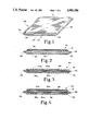
- FIG. 3 is a front elevational view in full section of the FIG. 1 insulation panel with a barrier pad of vibration-dampening insulation material disposed in the interior cavity.
- FIG. 4 is a front elevational view in full section of the FIG. 1 insulating panel including one barrier pad of vibration-dampening insulation material disposed on the exterior of the panel and a second barrier pad disposed on the interior of the insulation panel.
- FIG. 5 is a diagrammatic, perspective view of a manufacturing process which is suitable for production of the FIG. 1 insulation panel using particulate reducing material.
- FIGS. 5A and 5B are diagrammatic, perspective views of manufacturing processes suitable for production of the FIG. 1 insulation panel using bat and mat insulation material.
- FIG. 6 is a partial, diagrammatic, perspective view of an insulation panel bottom sheet with a particular shape of insulation material disposed thereon.
- FIG. 7 is an exploded, perspective view of an automatic dishwasher and insulation panel prior to assembly of the panel to the dishwasher and prior to assembly of the dishwasher into a cabinetwork opening.
- FIG. 8 is a top plan view of the FIG. 7 insulation panel with the diagrammatic addition of barrier pads of insulation material.
- FIG. 9 is a diagrammatic representation in cross-sectional view of a water heater device with a sealing and insulating device in place.
- FIG. 10 is a diagrammatic representation in cross-sectional view of one step in the process of achieving the FIG. 9 configuration.
- FIG. 11 is a diagrammatic representation in cross-sectional view of another step in the process of achieving the FIG. 9 configuration.
- FIG. 12 is a diagrammatic representation in cross-sectional view of yet another step in the process of achieving the FIG. 9 configuration.
- FIG. 13 is a diagrammatic, perspective representation of the sealing and insulating device of FIG. 9.
- FIG. 14 is an exploded, perspective diagrammatic representation of the installation of a dishwasher appliance incorporating a sealing and insulating device.
- FIG. 15 is a front view of the dishwasher appliance of FIG. 14 is installed in a confined space in a kitchen cabinetwork.
- an insulation panel 20 which is assembled as a lamination from three layers of material.
- the first layer or upper surface is a sheet 21 of a fluid impermeable, pliable material such as, for example, polyethylene film, vinyl film, polyester film, metalized polyester, metal foil such as aluminum foil and the like.
- the third or lower surface is a sheet 22 of the same kind of material.
- Disposed between top sheet 21 and bottom sheet 22 is the primary insulation material 23 which in one embodiment (FIG. 5) is a loose, discrete, divided material having thermal and/or acoustical insulation or abatement properties.
- insulation material 23 is bat or mat insulation.
- suitable materials for insulation material 23 are insulating non-interengaged fiberglass, mineral wool, cellulose, ceramic fiber, beads of plastic foam, particles of lead and the like.
- the specific insulation material for insulation material 23 would be a function of the end use and the environment in which the insulation panel 20 is used. Similarly, the material selection for top sheet 21 and bottom sheet 22 will also depend somewhat on the environment in which insulation panel 20 is used.
- a binder material may be dispersed throughout the mass of insulation material 23 in order to cohesively hold the insulation material together and prevent the insulation material 23 from shifting or settling within the cavity 24 which is defined by the top and bottom sheets, 21 and 22 respectively.
- the binder material used will be a function of the type of insulation material 23 and the environment in which the insulation panel is to be used.
- the binder material can be a thermosetting adhesive, a thermoplastic adhesive, a cold setting adhesive, a room or ambient setting, or a hot setting adhesive.
- the following is a list of appropriate binders for use with various types of insulation material 23 in order to produce insulation panel 20.
- top sheet 21 and bottom sheet 22 are drawn from large rolls or sheets which are generally of the width indicated in FIG. 1.
- the insulation material 23, with or without the binder material is then dispersed on bottom sheet 22 and top sheet 21 is thereafter applied to complete the lamination.
- the interior cavity 24 which is defined by top and bottom sheets 21 and 22 is completely filled with the insulation material 23.
- Outer edges 25 and 26 are sealed closed thereby defining the width boundaries for insulation panel 20.
- the particular technique for sealing these outer edges may be varied depending on the material and the particular production equipment available.
- One technique is to use a roller arrangement and heat or a suitable adhesive and by confining the dispersion of insulating material 23 within sheets 21 and 22 so as to leave an edge or peripheral border free of insulation, the sealing of these edges can be effected.
- leading edge 27 of the top and bottom sheets may also be sealed as the initial operation prior to dispersion of the insulating material onto the bottom sheet.
- this leading edge has not been sealed for illustrative purposes in order to be able to illustrate the interior cavity 24, the filling of that cavity with insulation material 23 and the lamination of that insulation material by top and bottom sheets 21 and 22.
- FIGS. 2-4 there are illustrated other arrangements for insulation panels according to the general principles and construction as described for FIG. 1. While the specific lamination configuration of FIGS. 2-4 are generally related, each figure depicts a particular lamination of vibration dampening and sound absorbing insulation materials which for the first time provides the efficiency and convenience of addressing both acoustical and vibrational concerns in a single prefabricated and specifically styled and contoured insulation panel. At this point, the particular peripheral geometry or contour is not discussed, only the lamination configuration and the materials which are used in that lamination.
- an insulation panel 30 which includes a top sheet 31, a bottom sheet 32, primary insulation material 33 disposed within interior cavity 34 which is created by sheets 31 and 32. Outer edges 35 and 36 are sealed as is the leading and trailing edges of insulation panel 30 such that the finished panel is completely enclosed on the top, bottom and all four edges.
- Top sheet 31 and bottom sheet 32 may be constructed of any of the materials previously mentioned for top and bottom sheets 21 and 22. In the preferred embodiment, sheets 31 and 32 will be constructed from polyethylene film, PVC film, or polypropylene film.
- the primary insulation material 33 which is disposed within interior cavity 34 is selected for the purposes of acoustical insulation or sound absorption.
- vibration barrier material insulation configured as a pad 38 may either be applied to the top outer surface (FIG. 2) of top sheet 31, or to the inside surface of top sheet 31 (not illustrated).
- This barrier insulation material pad 38 is adhesively joined to top sheet 31 or yet another alternative may be to dispose it within interior cavity 34 (as illustrated in FIG. 3).
- Appropriate dampening vibration materials insulation for the barrier pad 38 include loaded vinyl, loaded asphalt, and asphalt impregnated felt. When the barrier material pad is not directly applied to the vibrating surface, it may be thought of more as a transmission vibration barrier (see FIG. 3)
- insulation pads 20 and 30 are to be applied on, to an around appliances such as automatic dishwashers in order to provide adequate sound absorption and vibration dampening.
- the specific placement of the insulation panels will depend upon the brand and model of dishwasher, though the advantage of the present invention is the ability to prefabricate all necessary insulation panels such that they may simply be applied easily and directly at the time of manufacture and/or may be replaced as needed by repair or service personnel.
- Top and bottom sheets 21 and 22 as well as 31 and 32 have been described as coming off a large roll of a fixed width. It should be understood that these polyethylene type sheets or films may be obtained in a variety of lengths and widths and may be cut to any particular shape or contour. Similarly, the initial size of the sheets is selected so as to permit an adequate edge border for the purposes of sealing the top and bottom sheets so as to define the interior cavity. As would be expected, the thicker the cavity which is desired, the greater amount of material which will have to be left on the border so as to bend and form the sealing edge flanges while at the same time extending above and below those flanges to create the desired cavity thickness. This need for additional edge clearance is evident from the FIG.
- insulation panel 40 which includes top sheet 41 and bottom sheet 42.
- these top and bottom sheets may be of any suitable film material such as polyethylene, PVC or polypropylene.
- a pad 48 of vibration barrier insulation material insulation panel 40 between the top and bottom sheets there are in effect upper and lower portions of primary insulation material, and these are identified as primary insulation material 43a which is below the barrier pad 48 and 43b which is the primary insulation material above the pad.
- These upper and lower portions of insulation material completely fill the corresponding interior cavities 44a which is the lower cavity and 44b which is the upper cavity.
- the outer peripheral edges of the insulation panel 40 are sealed and while only outer edges 45 and 46 are illustrated, it is to be understood that the leading and trailing edges are similarly sealed by drawing together the outer film flanges and either adhesively or by heat joining those flanges of the top and bottom sheets together. While the leading edge is sealed initially prior to the application of the insulation material, the trailing edge will be sealed whenever the desired length of insulation panel has been fabricated. Depending upon the appliance and the intended use for the insulation panel, the overall length may vary as may the contour as will be described hereinafter.
- insulation panel 40 creates an upper and lower interior cavity
- the nature of the primary insulation materials 43a and 43b which are used to fill those cavities it is possible to vary the nature of the primary insulation materials 43a and 43b which are used to fill those cavities. Again, depending on the specific application and the specific appliance, it may be desired to put insulation material of different densities in the two cavities, depending upon the specific acoustical results desired.
- this material is a vibration dampening insulation material or transmission barrier and as previously described with regard to FIG. 2, may be loaded vinyl, loaded asphalt, or asphalt impregnated felt.
- Insulation panel 50 is virtually the same as insulation panel 40 with the lone exception that insulation panel 50 includes two vibration dampening barrier pads of vibration insulation material, either of which or both may be a transmission barrier. Otherwise, insulation panel is of a similar construction in that it includes top sheet 51, bottom sheet 52, insulation materials 53a and 53b which are arranged in lower interior cavity 54a and in upper interior cavity 54b and outer edges 55 and 56.
- Interior barrier pad (transmission barrier) 58 is of a suitable dampening material to reduce vibration and exterior barrier pad 59 may be of a similar vibration dampening insulation material.
- the insulation materials which are disposed in the cavities may be different materials since there are in fact two interior cavities.
- barrier pads 58 and 59 may be of different insulation materials and may be of different thicknesses and configurations.
- the method of fabrication for the types of insulation panels described in FIGS. 2-4 includes the initial laying down of the bottom sheet which then receives an application of the insulation material which may be applied from a bat or mat or as particulate with or without a binder. If nothing further is to be disposed within the interior region, then the top sheet is installed, the edges closed and the panel completed.
- a vibration barrier pad of insulation material is to be disposed within the enclosure formed by the top and bottom sheets, that barrier pad is applied next and directly onto the lower level of primary insulating material.
- the second or upper layer of primary insulation material is applied, again with or without a binder, and the final top sheet is applied and the edges sealed closed.
- the exterior barrier pad is adhesively joined to the outer surface.
- FIGS. 1-4 solves all of the aforementioned concerns and disadvantages with appliance insulation.
- the handling and contact concerns over fiberglass are eliminated by the encasement of that fiberglass insulation or fiberglass particles by the polyethylene film sheets which comprise the top and bottom sheets of each panel.
- Both acoustical insulation and vibration dampening insulation materials can be assembled together and the particular shape of the finished panel can be selectively configured for a particular make and model of appliance.
- a tougher, more-durable film such as polyethylene or polypropylene, the concerns over tearing of the insulation during packaging, shipment and installation are virtually eliminated.
- the flimsy, tear-prone insulation pads or blankets of the past are replaced by a durable and tough enclosed insulation panel without sacrificing any sound absorption properties.
- FIG. 5 the automated process for the lamination and assembly of one style of insulation panel 20 is illustrated.
- the FIG. 5 illustration utilizes particulate material 23, while FIGS. 5A and 5B utilize bat and mat insulation, respectively.
- Top sheet 21 of polyethylene film is drawn off of a larger roll 61 as is bottom sheet 22, though its supply roll is not illustrated.
- insulation material 23 is deposited from hose 62. If a binder (adhesive) is going to be applied to the insulation material as it is deposited on bottom sheet 22, then this adhesive is interspersed into the insulation material coming from hose 62.
- These adhesive nozzles are identified as nozzles 63.
- the insulation material is deposited down the middle of bottom sheet 22 leaving edges or edge boundary areas 64 and 65 free of insulation material.
- top sheet 21 is applied as a lamination over the insulation material and on top of bottom sheet 22, the edge boundary areas of sheets 21 and 22 are sealed.
- This sealing operation is diagrammatically represented by arrows 66 and as previously indicated, this edge-sealing operation may be done adhesively or by heat.
- FIG. 5A it is virtually identical in manufacturing concept to FIG. 5 except that hose 62 and nozzles 63 are replaced with a rolled bat of insulation material 67.
- this bat insulation is applied in a width slightly less than the width of top and bottom sheets 21 and 22. This allows the edges to be sealed so as to completely enclose the strip of bat insulation.
- a precut mat 68 of insulation is used, such as fiberglass which may be cut from a larger roll or bat.
- the bat or mat insulation may be applied without adhesive or may be adhesively joined to either sheet, typically bottom sheet 22. Additionally, other insulation may be still be added, under, over or around the mat and bat insulation.
- FIG. 6 a unique capability of the present invention is illustrated.
- the present invention enables a vibration barrier pad 70 of insulation material and of a specific and preselected size and contour to be applied directly to bottom sheet 22.
- Insulation material 23 has been omitted from the FIG. 6 illustration for the purposes of making it clear that the vibration barrier pad 70 may either go on top of insulation 23 or may go directly against the bottom sheet 22 in which the case the insulation material would be disposed solely on top of vibration barrier pad 70.
- the insulation panel being created is designed to be used on a particular appliance in a particular location where there is a particular vibration problem. It may be an area of motor, blower or pump or it may be a unique problem associated with the overall support and structure of the appliance. Whatever the particular cause or reason for the vibration, the insulation panel concept of the present invention enables a pad of vibration-dampening insulation material to be selectively placed and incorporated within the acoustical absorption insulation material such that when the insulation panel is applied to the appliance at the desired location, vibration-dampening is automatically achieved without the need for multiple assembly steps and multiple insulation and dampening panels being created.
- the insulation panel of the present invention is used for an automatic dishwasher which was specific acoustical insulation needs and certain vibration dampening needs.
- thermal insulation requirements there may also be thermal insulation requirements in which case the particular primary insulation material selected or the vibration barrier insulation material selected may include thermal properties which would be adequate for the particular problem.
- barrier pad 58 could provide the vibration dampening needs while barrier pad 59 which is disposed on the outside surface could provide the thermal insulation requirements.
- FIG. 7 an automatic dishwasher prior to installation beneath the countertop within the cabinetwork of a kitchen is illustrated.
- the automatic dishwasher is illustrated as including motor compartment insulation, vibration dampening material pads applied to the diswasher enclosure and a blanket of insulation 81 which is a T-shaped member having a top, sides and a back panel and this blanket insulation is constructed according to the teachings of FIG. 1 of the present invention.
- the panel construction as illustrated by FIGS. 2-4 could also be employed for the construction of the surrounding insulation blanket.
- automatic dishwasher 73 which includes enclosure 74 which may be sheet metal or plastic and motor compartment 75.
- enclosure 74 which may be sheet metal or plastic and motor compartment 75.
- barrier pads 76 and 77 of vibration dampening insulation material are illustrated as being applied to the top and side of the dishwasher with sound insulation strips 78 and 79 being positioned on opposite sides of the motor compartment.
- the blanket insulation 81 includes insulation side panels 82 and 83, a top insulation panel 84 and a rear insulation panel 85.
- insulation blanket 81 slides over and around automatic dishwasher 73 so as to provide acoustical insulation adjacent the sides, top and rear wall portions of the automatic dishwasher. It is also to be understood that barrier pads 76 and 77 may be built into insulation blanket 81 as previously described and as further illustrated in FIG. 8.
- each such panel as a generally rectangular panel whose width was fixed and length variable as the panel is produced from rolled sheets of polyethylene film.
- the unfolded and laid-flat insulation blanket 81 is illustrated.
- This blanket has been drawn with fold lines 88, 89 and 90 so as to establish the separation between left and top insulation panels, the right and top insulation panels and the top and rear insulation panels.
- fold lines 88, 89 and 90 which are indicated by broken lines may simply be folds in the panel or may be lines which are heat-welded so as to define discrete pouches for the insulation material wherein each side panel or portion is a separate and distinct insulation panel. Heat welding of these seams creates a type of living hinge which facilitates placement of the insulation blanket around the dishwasher and makes it clear as to where the fold lines should be so that the left and right side panels and the top and rear insulation panels conform properly to the dishwasher.
- vibration barrier pads 76 and 77 are also illustrated in FIG. 8 as vibration barrier pads 76 and 77 as laminated into the top insulation panel 84 and the left side insulation panel 82, respectively.
- particulate matter such as fiberglass provides an efficient and cost-effective approach since the particulate which is used may include scrap material and remainders which are not of sufficient size for any other purpose. It is also possible to employ the polyethylene top and bottom sheets so as to enclose bat insulation or a mat insulation in accordance with the teachings of this invention.
- the bat (or mat) insulation may be laminated loosely or may be secured in place by the use of a suitable adhesive.
- one prefabrication concept includes the use of double-sided adhesive applied directly to the polyethylene material of the top and bottom sheets.
- the cover paper is peeled away and the insulation blanket stuck directly to the appliance.
- a further feature of the present invention and one which has been previously commented upon involves the concept of using thick sections of insulation so as to completely and tightly fill spaces or cavities existing either within the particular appliance (hot water heater) or between the appliance and the surrounding environment (automatic dishwasher).
- hot water heater hot water heater
- automated dishwasher automated dishwasher
- the insulation panels of the present invention where their convenience, simplicity, unique configuration which includes both acoustical insulation and vibration dampening within a single insulation pad and which provides the much-needed tear resistance.
- the space between the exterior of the dishwasher and the interior surface of the opening created below the kitchen counter needs to be tightly filled with insulation to the greatest degree possible both for a snug fit of the dishwasher within the prepared opening and for optimum acoustical insulation and vibrational dampening.
- One aspect of the present invention which enables very thick sections of insulation to be incorporated into a final assembly while at the same time not tearing or rolling up during installation is a vacuum technique which draws the air out of the particulate insulation enabling the thickness of the insulation panel to be substantially reduced thereby easing installation.
- Hot water heater 110 includes an inner water tank 112 for containing water and an outer shell 114 which is concentrically configured so as to surround the inner water tank 112.
- the outer shell 114 and inner water tank 112 cooperate so as to define an annular space 116 therebetween.
- the hot water heater 110 is of the gas fired type having a combustion chamber 118 located at the bottom end of the interior water tank 112.
- a combustion or gas burner (not shown) is located within the combustion chamber 118.
- the bottom of the annular space 116 can be closed by a bottom wall 120, and the top of the water heater 110 is closed by a top wall 122.
- a sealing and insulation device 124 is positioned within the annular space 116 in abutting contact with the first or exterior surface of the water tank 112 and the second or interior surface of outer shell 114.
- the sealing and insulation device 124 is shown in FIGS. 10-13 as comprising a closed, elongated envelope 126 fabricated of a resilient, gas impermeable material.
- the material can be, for example, a thermal plastic film such as polyethylene film or polypropylene film.
- Enclosed envelope 126 is filled with a resilient insulation material 128 such as interengaged or non-interengaged fibrous material, for example, fiberglass, mineral wool, cellulose, ceramic fiber, or divided, discrete particles of a material, for example, beads or plastic foam, oil resilient flexible foam, for example, a flexible urethane foam.
- the specific insulation material used will be a function of the end use and environment.
- the length of the envelope 126 of the insulation device 124 is sufficient to circumscribe the annular space 116 with the ends of the envelope 126 in neutral end-to-end or overlapping abutment.
- the thickness or width dimension of the envelope 126 is at least equal to the transverse dimension of the space 116 so as to be in abutting contact with both the exterior surface of the water tank 112 and the interior surface of the outer shell 114 across the space 116.
- the sealing and insulating device 124 is positioned on the first surface or exterior surface of the inner water tank 112 at a preselected location thereon.
- the sealing and insulation device 124 is wrapped around the circumference of the inner water tank 112 at a location just above the combustion chamber 118.
- the circumscribed envelope 126 is fastened to the exterior surface of the water tank 112 to prevent it from moving. This can be done using, for example, an adhesive or tape. If the sealing and insulation device 124 is located above the combustion chamber 118, a mat of insulation material 130 of fire-resistant material should be located within the space 116 below the sealing and insulation device 124 circumscribing the combustion chamber 118.
- air is evacuated from the interior of the sealing and insulation device 124 in order to shrink and reduce the thickness of the sealing and insulation device 124 to a dimension less than the width of the space 116 between the first or exterior surface of the water tank 112 and the second or interior surface of the outer shell 114.
- the removal of the air can be accomplished by using a vacuum pump 132 which may be for example a household vacuum cleaner.
- the vacuum pump 132 has a flexible hose 134 with, for example, a piercing needle at the free inlet end thereof for piercing the envelope 126 of the sealing and insulation device 124.
- the free inlet end of the hose 134 is pressed against the sealing and insulation device 124 so the needle pierces the envelope 126 establishing gas communication between the inlet end of the hose 134 and the interior of the envelope 126.
- the vacuum pump 132 When the vacuum pump 132 is activated, air is removed from the interior of the sealing and insulation device 124 which causes the envelope 126 to shrink in at least the width to a dimension less than the transverse dimension of the space 116.
- the outer shell 114 is then positioned coaxially over the inner water tank 112 so that the second or interior surface of the outer shell 114 is in a spaced-apart relationship to the first or exterior wall surface of the water tank 112.
- the vacuum pump can be reversed or the hose 134 can be connected to an air pump to introduce air back into the envelope 126 or the inlet end of the vacuum pump hose 134 is removed for engagement with the sealing and insulation device 124 allowing ambient air to re-enter the envelope 126 of the sealing and insulation device 124 through the pierced hole therein in order to recover compressively or swell the sealing and insulation device 124 back to at least its original size such that it is in abutting contact with both the exterior surface of the water tank 112 and the interior surface of the outer shell 114 across the space 116 therebetween circumferentially of the space 116.
- the annular space 116 above the sealing and annular insulating device 124 is filled with an expanded foam insulation material 138 such as urethane, polyethylene, polystyrene and the like. Expandable foam insulation material is injection or otherwise placed in the annular space 116 above the sealing and insulation device 124 and allowed to expand in place filling the annular space 116 above the insulation device 124.
- the abutting contact of the sealing and insulation device 124 with the exterior surface of the water tank 112 and the interior surface of the outer shell 114 resists the pressure generated by the expanding foaming material 138 and seals across the space 116 to prevent leakage of the foam material past the sealing and insulation device 124 as it is expanding in the space 116 above the sealing and insulation device 124.
- the sealing and insulation device 124 functions to insulate the portion of the space 116 in which it is located and also functions as a seal or stop for the expanding foam material 138 from leaking past the sealing and insulation device 124.
- the sealing and insulation device 124 could be positioned on the interior surface of the outer shell 114, then evacuated of air and next the water tank 112 would be positioned coaxially within the outer shell 114 in space-apart relationship to define the space 116. Air is then allowed to re-enter the envelope 126 of the sealing and insulation device 124 swelling the sealing and insulation device 124 back to at least its original size such that it is in contact with both the exterior surface of the tank 112 and interior surface of the shell 114.
- the outer shell can be positioned coaxially over the inner water tank so that the second interior surface of the outer shell is in spaced-apart relationship to the first or exterior wall surface of the water tank.
- Air is then evacuated from the interior of the sealing and insulation device 124 which causes the envelope 126 to shrink in at least the width dimension to a dimension which is less than the transverse dimension of space 116.
- the sealing and insulation device 124 is then positioned in space 116 and when correctly in position a vacuum pump which was used to evacuate the device can be reversed or the hose 134 can be connected to an air pump to introduce air back into the envelope 126.
- ambient air can be allowed to re-enter the envelope 126 through the pierced hole therein in order to swell the sealing and insulation device 124 back to at least its original size such that it is in abutting contact with both the first or exterior surface of the water tank 112 and the second or interior surface of the outer shell 114 across space 116.
- the expandable foam insulation material 138 is then introduced into the annular space 116 and allowed to expand in place.
- a nozzle or opening can be provided in any one or all of the individual insulation panel portions such that these individual panels, namely the left and right side panels, the top panel and the rear panel can be individually and selectively filled with different thicknesses of insulation and can be individually and selectively evacuated for a thinner cross-section at the time of assembly.
- the versatility afforded in the evacuation of individual panels or pouches is consistent with the versatility afforded by the lamination construction and versatility afforded by varying materials which can be used for acoustical insulation, vibration dampening and thermal insulation, all depending on the particular make and model of appliance and the particular environment.
- a dishwasher apparatus 150 having a housing 151 which is to be installed within the confines of an opening 152 formed in a kitchen cabinetwork 153.
- the exterior surface of the dishwasher housing 151 can be considered a first surface of two spaced-apart surfaces, and the edge 154 of the opening 152 can be considered to be a second surface of the two spaced-apart surfaces.
- a sealing and insulation device 155 is shown as comprising a closed elongated envelope 156 fabricated of a resilient, gas-impermeable material.
- the material can be, for example, a thermoplastic film such as polyethylene film or polypropylene film.
- the closed envelope 156 is filled with a resilient insulation material 157 such as interengaged or non-interengaged fibrous material, for example, fiberglass, mineral wool, cellulose, ceramic fiber, or divided, discrete particles of material, for example, beads of plastic foam or resilient foam such as flexible urethane foam and the like.
- the specific insulation material used will be a function of the end use of the environment.
- the insulation material can be more generally thought of as a reducing material whose composition is selected depending upon which undesirable side effects of the dishwasher are being material whose composition is selected depending upon which undesirable side effects of the dishwasher are being addressed. If noise absorption or reduction is a concern then the insulation material (reducing material) is selected principally for noise abatement results. Similarly, if one of the objectives is vibration-dampening, then the material enclosed within elongated envelope 156 is selected for that purpose. Finally, if thermal insulation is important such as placement of the envelope over a heat source, then the reducing material selected should have good thermal insulating properties. It is also possible as previously described in this application to combine different materials so that a combination of undesirable side effects can be addressed by a single insulation device 155.
- the length of the envelope 156 of sealing and insulating device 155 is sufficient to overlay the two sides and top of the dishwasher housing 151.
- the thickness or width dimension of the envelope 156 is at least equal to the transverse dimension of the space 160 between the first or exterior surface of the dishwasher housing 151 and the second or edge 154 of the opening 152 so as to be in abutting contact with both the first and second surfaces across space 160.
- the sealing and insulating device 155 is positioned on the exterior surface of the dishwasher housing 151 overlying the two sides and top surface of the housing.
- the sealing and insulation device can be attached directly to the dishwasher housing by, for example, an adhesive or tape if desired or required to keep the insulation device from moving or shifting.
- air is evacuated from the interior of the sealing and insulation device 155 in order to shrink it and reduce the thickness or width dimension to a dimension which is less than the width of space 160. The removal of air can be accomplished in the manner previously described with regard to the insulation device used in the hot water heater.
- the dishwasher apparatus 150 is then positioned within the opening 152 of the cabinetwork.
- the vacuum pump used to remove the air from the insulation device can be reversed or alternatively a flexible hose 134 can be connected to an air pump in order to introduce air back into envelope 156.
- a still further alternative is to simply leave a small opening in the sealing and insulation device and allow ambient air to be introduced or reinter the envelope 156 so that it returns back to at least its original size such that it is in abutting contact with both the exterior surface of the dishwasher apparatus housing and the edge 154 of the cabinetwork opening across space 160.
- the vacuum can be reapplied to the insulation device so as to reduce its thickness and thereby take it out of abutment contact with the cabinetwork opening.
- the dishwasher may be easily removed and serviced and then the process repeated for reinstallation of the dishwasher into the cabinetwork opening.
Abstract
Description
______________________________________
Insulation Material
                  Binder
______________________________________
fiberglass        phenolic, sodium silicate
mineral wool      phenolic, sodium silicate
cellulose         polyvinyl acetate
sand particles    polyvinyl acetate
lead particles    polyvinyl acetate
______________________________________
Claims (24)
Priority Applications (2)
| Application Number | Priority Date | Filing Date | Title |
|---|---|---|---|
| US07220027 US4985106B1 (en) | 1986-11-17 | 1988-07-15 | Insulation structure for appliances |
| US07509899 US5044705B1 (en) | 1986-11-17 | 1990-04-16 | Insulation structure for appliances |
Applications Claiming Priority (3)
| Application Number | Priority Date | Filing Date | Title |
|---|---|---|---|
| US93115086A | 1986-11-17 | 1986-11-17 | |
| US17743988A | 1988-04-04 | 1988-04-04 | |
| US07220027 US4985106B1 (en) | 1986-11-17 | 1988-07-15 | Insulation structure for appliances |
Related Parent Applications (2)
| Application Number | Title | Priority Date | Filing Date |
|---|---|---|---|
| US93115086A Continuation-In-Part | 1986-11-17 | 1986-11-17 | |
| US17743988A Continuation-In-Part | 1986-11-17 | 1988-04-04 |
Related Child Applications (1)
| Application Number | Title | Priority Date | Filing Date |
|---|---|---|---|
| US07509899 Continuation US5044705B1 (en) | 1986-11-17 | 1990-04-16 | Insulation structure for appliances |
Publications (2)
| Publication Number | Publication Date |
|---|---|
| US4985106A true US4985106A (en) | 1991-01-15 |
| US4985106B1 US4985106B1 (en) | 1997-06-17 |
Family
ID=26873292
Family Applications (1)
| Application Number | Title | Priority Date | Filing Date |
|---|---|---|---|
| US07220027 Expired - Lifetime US4985106B1 (en) | 1986-11-17 | 1988-07-15 | Insulation structure for appliances |
Country Status (1)
| Country | Link |
|---|---|
| US (1) | US4985106B1 (en) |
Cited By (60)
| Publication number | Priority date | Publication date | Assignee | Title |
|---|---|---|---|---|
| US5044705A (en) * | 1986-11-17 | 1991-09-03 | Soltech, Inc. | Insulation structure for appliances |
| US5084313A (en) * | 1988-12-16 | 1992-01-28 | Meyer Tool And Manufacturing, Inc. | Insulating material and method of making same |
| US5100016A (en) * | 1989-12-12 | 1992-03-31 | Rock-Tenn Company | Insulating blanket for shipping container |
| US5142842A (en) * | 1989-12-13 | 1992-09-01 | W. R. Grace & Co.-Conn. | Method for making a film/foil panel |
| US5273801A (en) * | 1991-12-31 | 1993-12-28 | Whirlpool Corporation | Thermoformed vacuum insulation container |
| US5549760A (en) * | 1994-12-01 | 1996-08-27 | White Consolidated Industries, Inc. | Mounting device for dishwasher insulation |
| US5827385A (en) * | 1994-07-15 | 1998-10-27 | Vacupanel, Inc. | Method of producing an evacuated insulated container |
| WO1998059125A1 (en) * | 1997-06-24 | 1998-12-30 | Owens Corning | Vacuum packaged batt |
| US5866858A (en) * | 1996-03-26 | 1999-02-02 | Dewey; Jon Severen | Loudspeaker method and apparatus |
| US6018842A (en) * | 1997-08-13 | 2000-02-01 | Billco Manufacturing, Inc. | Glass washing machine |
| WO2001007848A1 (en) * | 1999-07-23 | 2001-02-01 | BSH Bosch und Siemens Hausgeräte GmbH | Heat-insulating wall |
| WO2002026100A2 (en) * | 2000-09-29 | 2002-04-04 | Owens Corning | Acoustical insulation blanket for dishwasher |
| NL1016899C2 (en) * | 2000-12-18 | 2002-06-19 | Rubber Design B V | Insulation element with multi layer flexible core, has fireproof flexible mantle |
| US20020106499A1 (en) * | 2000-01-31 | 2002-08-08 | Cartier John L. | Ice breaker mat |
| US20030008592A1 (en) * | 2000-06-30 | 2003-01-09 | Block Thomas L. | Hood, dash, firewall or engine cover liner |
| US6572723B1 (en) | 2000-06-30 | 2003-06-03 | Owens Corning Fiberglas Technology, Inc. | Process for forming a multilayer, multidensity composite insulator |
| EP1353018A1 (en) * | 2002-04-12 | 2003-10-15 | Serge Branlant | Sratified material for thermal insulation, its process of manufacturing and device for its implementation |
| US6669265B2 (en) | 2000-06-30 | 2003-12-30 | Owens Corning Fiberglas Technology, Inc. | Multidensity liner/insulator |
| US20040014382A1 (en) * | 2002-07-18 | 2004-01-22 | Macaulay John J. | Laminate and use of such laminate as a facer in making insulation boards and other products |
| US20040060644A1 (en) * | 2000-02-01 | 2004-04-01 | Peter Danko | Method and apparatus for closing an open end of a product, and product formed thereby |
| US20040069527A1 (en) * | 2002-10-14 | 2004-04-15 | Carl Vanhoutte | Laminated bus bar assembly |
| US6726980B2 (en) * | 2001-11-09 | 2004-04-27 | Owens Corning Fiberglass Technology, Inc. | Acoustic doorliner with integral water barrier |
| US6851229B2 (en) * | 2001-09-14 | 2005-02-08 | Metal-Era, Inc. | Anchor bar splice |
| US20050058790A1 (en) * | 1996-01-11 | 2005-03-17 | Robert Simon | Metallized heat resistant material with thermal barrier |
| US20050092353A1 (en) * | 2003-10-29 | 2005-05-05 | Retsema Andrew J. | Dishwasher and motor cavity sound attenuator |
| US20050155881A1 (en) * | 2002-08-08 | 2005-07-21 | Hitchings Timothy J. | Method of producing a data disk holder with adhesive seal strip |
| US20050208263A1 (en) * | 2004-03-05 | 2005-09-22 | Reiner Wilkens | Composite component |
| US6955845B1 (en) * | 2000-06-30 | 2005-10-18 | Owens Corning Fiberglas Technology, Inc. | Acoustical and thermal insulator |
| FR2869972A1 (en) * | 2004-05-07 | 2005-11-11 | Saipem S A Sa | ISOLATING COMPLEX WITH METAL ENVELOPE FOR DRIVING |
| US20060037630A1 (en) * | 2004-08-03 | 2006-02-23 | Rowland Griffin | Acoustic insulation blanket for dishwashers |
| US7040329B2 (en) * | 2002-05-03 | 2006-05-09 | Whirlpool Corporation | Low-noise in-sink dishwasher |
| US20070042156A1 (en) * | 2005-08-22 | 2007-02-22 | Rockwell Anthony L | Die cut insulation blanket and method for producing same |
| US20070095454A1 (en) * | 2004-09-02 | 2007-05-03 | Panther Allen L | Ultrasonic joining of polymer mats to mechanical devices including electric appliances |
| US20070102029A1 (en) * | 2005-11-04 | 2007-05-10 | Panther Allen L | Acoustic seal for use in kitchen appliance |
| US20070113800A1 (en) * | 2005-11-23 | 2007-05-24 | Bradford White Corporation | Water heater and system for insulating same |
| FR2897139A1 (en) * | 2006-02-08 | 2007-08-10 | Kdb Isolation Sa | Multi-functional, especially thermal, insulating material has thermal insulation strip on one inner face of overlapping joint zone to prevent thermal bridge |
| WO2007100830A2 (en) * | 2006-02-27 | 2007-09-07 | Owens Corning Intellectual Capital, Llc | Appliance noise reduction blanket |
| US7297384B2 (en) | 2004-12-07 | 2007-11-20 | Shawn Kelly Crowley | Metallized heat resistant material with thermal barrier |
| US20080022620A1 (en) * | 2006-06-26 | 2008-01-31 | Shawn Crowley | Flexible weather resistant building wrap |
| US20080032077A1 (en) * | 2005-12-07 | 2008-02-07 | Crowley Shawn K | Metallized heat resistant material with thermal barrier |
| US20080128005A1 (en) * | 2006-12-01 | 2008-06-05 | Electrolux Home Products, Inc. | Dishwasher apparatus including sound absorbing device |
| US20080190806A1 (en) * | 2005-03-11 | 2008-08-14 | Lg Electronics Inc. | Protection Pad for Home Appliances |
| US20090095234A1 (en) * | 2007-10-16 | 2009-04-16 | Bradford White Corporation | Water heater and system for insulating same |
| US20100024851A1 (en) * | 2008-08-04 | 2010-02-04 | Rockwell Anthony L | Insulation Element For An Electrical Appliance Such As A Dishwasher |
| US20100062921A1 (en) * | 2008-09-11 | 2010-03-11 | Simple Container Solutions, Inc. | Expandable insulated packaging |
| US20110088805A1 (en) * | 2009-10-20 | 2011-04-21 | Nakagawa Sangyo Co., Ltd. | Heat insulator suitable for a vehicle exhaust pipe |
| US8061478B2 (en) | 2008-05-06 | 2011-11-22 | Moderco Inc. | Acoustic face of polymer and embedded coarse aggregates and an acoustic panel assembly |
| US20120013228A1 (en) * | 2010-07-16 | 2012-01-19 | BSH Bosch und Siemens Hausgeräte GmbH | Method for manufacturing a dishwasher with at least one, especially prefabricated, bitumen mat for deadening of noise and/or sound absorption of a component |
| US8133568B2 (en) | 2005-08-22 | 2012-03-13 | Owens Corning Intellectual Capital, Llc | Die cut insulation blanket |
| US20120260862A1 (en) * | 2011-04-14 | 2012-10-18 | Alexander Paul H | Vibration Reduction Pad |
| CN104723029A (en) * | 2014-07-25 | 2015-06-24 | 芜湖美的洗涤电器制造有限公司 | Inner container manufacturing method and dish washing machine |
| US9175863B2 (en) | 2007-04-09 | 2015-11-03 | Owens Corning Intellectual Capital, Llc | Insulation configuration for thermal appliances |
| EP2572621A3 (en) * | 2011-09-21 | 2016-03-02 | Whirlpool Corporation | Dishwasher with multi-piece tub |
| CN105534454A (en) * | 2016-01-22 | 2016-05-04 | 宁波欧琳厨具有限公司 | Noise-reduction and heat-insulation door sheet for cleaning device |
| CN105980126A (en) * | 2014-02-06 | 2016-09-28 | 巴斯夫欧洲公司 | Insulating assembly for a storage vessel and process for preparation thereof |
| US9510724B2 (en) | 2011-09-21 | 2016-12-06 | Whirlpool Corporation | Dishwasher with multi-piece tub |
| US9714480B2 (en) | 2011-05-24 | 2017-07-25 | Owens Corning Intellectual Capital, Llc | Acoustically insulated machine |
| US9845564B2 (en) | 2010-12-31 | 2017-12-19 | Owens Corning Intellectual Capital, Llc | Appliance having a housing dampening portion and method |
| US11141952B2 (en) | 2015-04-06 | 2021-10-12 | Industrial & Environmental Concepts, Inc. | Sludge covers, sludge management systems, and related methods |
| CN113646162A (en) * | 2019-02-08 | 2021-11-12 | 杜邦安全与建筑公司 | Flame-retardant and heat-insulating material suitable for battery unit |
Citations (26)
| Publication number | Priority date | Publication date | Assignee | Title |
|---|---|---|---|---|
| US137145A (en) * | 1873-03-25 | Improvement in sieves for separators | ||
| US174534A (en) * | 1876-03-07 | Improvement in bottle-stoppers | ||
| US174535A (en) * | 1876-03-07 | Improvement in curtain-fixtures | ||
| US1880153A (en) * | 1931-03-19 | 1932-09-27 | Rosenzweig Siegfried | Sound insulating and vibration dampening structural unit |
| US1923195A (en) * | 1928-11-09 | 1933-08-22 | Joseph L Finck | Heat insulating structure |
| US1949677A (en) * | 1931-06-16 | 1934-03-06 | Crawford Wllbur Francis | Shipping jacket for ice cream |
| US2013914A (en) * | 1932-07-27 | 1935-09-10 | Morgan J Doyle | Electric water heater |
| US2216809A (en) * | 1937-08-10 | 1940-10-08 | Norman L Derby | Heater and thermo control therefor |
| US2365086A (en) * | 1943-09-21 | 1944-12-12 | Joseph T Kamowski | Thermal insulating jacket |
| US2700633A (en) * | 1952-05-02 | 1955-01-25 | Gen Electric | Insulating structure and method of forming same |
| US2817124A (en) * | 1956-02-08 | 1957-12-24 | Gen Motors Corp | Refrigeration apparatus |
| US2927626A (en) * | 1958-02-03 | 1960-03-08 | Robert G Corwin | Insulating blanket for concrete |
| US3056708A (en) * | 1959-05-13 | 1962-10-02 | West Virginia Pulp & Paper Co | Mineral fiber mat formation |
| US3502843A (en) * | 1968-09-30 | 1970-03-24 | Chester Lewis Stryer | Electric water heating unit |
| US3730144A (en) * | 1972-02-17 | 1973-05-01 | Jet Spray Cooler Inc | Hot water tank |
| US4039098A (en) * | 1976-01-05 | 1977-08-02 | Kenneth Morris Stilts | Thermal insulation jacket for water heaters |
| US4269890A (en) * | 1977-10-25 | 1981-05-26 | Daimler-Benz Aktiengesellschaft | Process and apparatus for introducing foam into automobile body cavities |
| US4282279A (en) * | 1979-10-16 | 1981-08-04 | Rip 'n Rap, Inc. | Formable removable insulating enclosure for a container |
| US4318427A (en) * | 1980-10-31 | 1982-03-09 | Cross Jr Roger H | Thermal insulation system |
| US4350001A (en) * | 1975-11-18 | 1982-09-21 | Tex Innovation Ab | Method for treating insulating fiber |
| US4372028A (en) * | 1980-10-06 | 1983-02-08 | Rheem Manufacturing Company | Method of manufacturing foam insulated tank |
| US4403023A (en) * | 1980-10-09 | 1983-09-06 | Brown, Boveri & Cie Ag | Thermal insulation |
| US4447377A (en) * | 1979-12-10 | 1984-05-08 | State Industries, Inc. | Method of insulating the exterior of a water heater tank |
| US4477399A (en) * | 1982-06-16 | 1984-10-16 | Gsw Inc. | Method and apparatus for manufacturing a foam insulated water heater |
| US4510890A (en) * | 1983-04-11 | 1985-04-16 | Cowan Edwin J | Infrared water heater |
| US4739781A (en) * | 1985-03-13 | 1988-04-26 | Top S.R.L. | Compact top loading dishwasher suitable for fitting inside furniture units |
-
1988
- 1988-07-15 US US07220027 patent/US4985106B1/en not_active Expired - Lifetime
Patent Citations (26)
| Publication number | Priority date | Publication date | Assignee | Title |
|---|---|---|---|---|
| US137145A (en) * | 1873-03-25 | Improvement in sieves for separators | ||
| US174534A (en) * | 1876-03-07 | Improvement in bottle-stoppers | ||
| US174535A (en) * | 1876-03-07 | Improvement in curtain-fixtures | ||
| US1923195A (en) * | 1928-11-09 | 1933-08-22 | Joseph L Finck | Heat insulating structure |
| US1880153A (en) * | 1931-03-19 | 1932-09-27 | Rosenzweig Siegfried | Sound insulating and vibration dampening structural unit |
| US1949677A (en) * | 1931-06-16 | 1934-03-06 | Crawford Wllbur Francis | Shipping jacket for ice cream |
| US2013914A (en) * | 1932-07-27 | 1935-09-10 | Morgan J Doyle | Electric water heater |
| US2216809A (en) * | 1937-08-10 | 1940-10-08 | Norman L Derby | Heater and thermo control therefor |
| US2365086A (en) * | 1943-09-21 | 1944-12-12 | Joseph T Kamowski | Thermal insulating jacket |
| US2700633A (en) * | 1952-05-02 | 1955-01-25 | Gen Electric | Insulating structure and method of forming same |
| US2817124A (en) * | 1956-02-08 | 1957-12-24 | Gen Motors Corp | Refrigeration apparatus |
| US2927626A (en) * | 1958-02-03 | 1960-03-08 | Robert G Corwin | Insulating blanket for concrete |
| US3056708A (en) * | 1959-05-13 | 1962-10-02 | West Virginia Pulp & Paper Co | Mineral fiber mat formation |
| US3502843A (en) * | 1968-09-30 | 1970-03-24 | Chester Lewis Stryer | Electric water heating unit |
| US3730144A (en) * | 1972-02-17 | 1973-05-01 | Jet Spray Cooler Inc | Hot water tank |
| US4350001A (en) * | 1975-11-18 | 1982-09-21 | Tex Innovation Ab | Method for treating insulating fiber |
| US4039098A (en) * | 1976-01-05 | 1977-08-02 | Kenneth Morris Stilts | Thermal insulation jacket for water heaters |
| US4269890A (en) * | 1977-10-25 | 1981-05-26 | Daimler-Benz Aktiengesellschaft | Process and apparatus for introducing foam into automobile body cavities |
| US4282279A (en) * | 1979-10-16 | 1981-08-04 | Rip 'n Rap, Inc. | Formable removable insulating enclosure for a container |
| US4447377A (en) * | 1979-12-10 | 1984-05-08 | State Industries, Inc. | Method of insulating the exterior of a water heater tank |
| US4372028A (en) * | 1980-10-06 | 1983-02-08 | Rheem Manufacturing Company | Method of manufacturing foam insulated tank |
| US4403023A (en) * | 1980-10-09 | 1983-09-06 | Brown, Boveri & Cie Ag | Thermal insulation |
| US4318427A (en) * | 1980-10-31 | 1982-03-09 | Cross Jr Roger H | Thermal insulation system |
| US4477399A (en) * | 1982-06-16 | 1984-10-16 | Gsw Inc. | Method and apparatus for manufacturing a foam insulated water heater |
| US4510890A (en) * | 1983-04-11 | 1985-04-16 | Cowan Edwin J | Infrared water heater |
| US4739781A (en) * | 1985-03-13 | 1988-04-26 | Top S.R.L. | Compact top loading dishwasher suitable for fitting inside furniture units |
Cited By (94)
| Publication number | Priority date | Publication date | Assignee | Title |
|---|---|---|---|---|
| US5044705A (en) * | 1986-11-17 | 1991-09-03 | Soltech, Inc. | Insulation structure for appliances |
| US5084313A (en) * | 1988-12-16 | 1992-01-28 | Meyer Tool And Manufacturing, Inc. | Insulating material and method of making same |
| US5100016A (en) * | 1989-12-12 | 1992-03-31 | Rock-Tenn Company | Insulating blanket for shipping container |
| US5142842A (en) * | 1989-12-13 | 1992-09-01 | W. R. Grace & Co.-Conn. | Method for making a film/foil panel |
| US5273801A (en) * | 1991-12-31 | 1993-12-28 | Whirlpool Corporation | Thermoformed vacuum insulation container |
| US5827385A (en) * | 1994-07-15 | 1998-10-27 | Vacupanel, Inc. | Method of producing an evacuated insulated container |
| US5549760A (en) * | 1994-12-01 | 1996-08-27 | White Consolidated Industries, Inc. | Mounting device for dishwasher insulation |
| US20050058790A1 (en) * | 1996-01-11 | 2005-03-17 | Robert Simon | Metallized heat resistant material with thermal barrier |
| US5866858A (en) * | 1996-03-26 | 1999-02-02 | Dewey; Jon Severen | Loudspeaker method and apparatus |
| US5987833A (en) * | 1997-06-24 | 1999-11-23 | Owens Corning Fiberglas Technology, Inc. | Vacuum packaged batt |
| WO1998059125A1 (en) * | 1997-06-24 | 1998-12-30 | Owens Corning | Vacuum packaged batt |
| US6018842A (en) * | 1997-08-13 | 2000-02-01 | Billco Manufacturing, Inc. | Glass washing machine |
| WO2001007848A1 (en) * | 1999-07-23 | 2001-02-01 | BSH Bosch und Siemens Hausgeräte GmbH | Heat-insulating wall |
| CN1318813C (en) * | 1999-07-23 | 2007-05-30 | Bsh博施及西门子家用器具有限公司 | Heat-insulating wall |
| US6725624B2 (en) | 1999-07-23 | 2004-04-27 | Bsh Bosch Und Siemens Aktiengesellschaft | Heat-insulating walling |
| US20020106499A1 (en) * | 2000-01-31 | 2002-08-08 | Cartier John L. | Ice breaker mat |
| US7951252B2 (en) * | 2000-02-01 | 2011-05-31 | Peter Danko | Method and apparatus for closing an open end of a product, and product formed thereby |
| US20040060644A1 (en) * | 2000-02-01 | 2004-04-01 | Peter Danko | Method and apparatus for closing an open end of a product, and product formed thereby |
| US20030008592A1 (en) * | 2000-06-30 | 2003-01-09 | Block Thomas L. | Hood, dash, firewall or engine cover liner |
| JP4831920B2 (en) * | 2000-06-30 | 2011-12-07 | オウェンス コーニング インテレクチュアル キャピタル リミテッド ライアビリティ カンパニー | Soundproof and heat insulating material |
| US6669265B2 (en) | 2000-06-30 | 2003-12-30 | Owens Corning Fiberglas Technology, Inc. | Multidensity liner/insulator |
| US6572723B1 (en) | 2000-06-30 | 2003-06-03 | Owens Corning Fiberglas Technology, Inc. | Process for forming a multilayer, multidensity composite insulator |
| US8361912B2 (en) | 2000-06-30 | 2013-01-29 | Owens Corning Intellectual Capital, Llc | Hood, dash, firewall or engine cover liner |
| US6955845B1 (en) * | 2000-06-30 | 2005-10-18 | Owens Corning Fiberglas Technology, Inc. | Acoustical and thermal insulator |
| WO2002026100A2 (en) * | 2000-09-29 | 2002-04-04 | Owens Corning | Acoustical insulation blanket for dishwasher |
| US6539955B1 (en) | 2000-09-29 | 2003-04-01 | Owens Corning Fiberglas Technology, Inc. | Acoustical insulation blanket for dishwasher |
| WO2002026100A3 (en) * | 2000-09-29 | 2002-06-06 | Owens Corning Fiberglass Corp | Acoustical insulation blanket for dishwasher |
| NL1016899C2 (en) * | 2000-12-18 | 2002-06-19 | Rubber Design B V | Insulation element with multi layer flexible core, has fireproof flexible mantle |
| US6851229B2 (en) * | 2001-09-14 | 2005-02-08 | Metal-Era, Inc. | Anchor bar splice |
| US6726980B2 (en) * | 2001-11-09 | 2004-04-27 | Owens Corning Fiberglass Technology, Inc. | Acoustic doorliner with integral water barrier |
| EP1353018A1 (en) * | 2002-04-12 | 2003-10-15 | Serge Branlant | Sratified material for thermal insulation, its process of manufacturing and device for its implementation |
| FR2838466A1 (en) * | 2002-04-12 | 2003-10-17 | Serge Branlant | LAMINATE THERMAL INSULATION MATERIAL AND MANUFACTURING METHOD THEREOF |
| US7040329B2 (en) * | 2002-05-03 | 2006-05-09 | Whirlpool Corporation | Low-noise in-sink dishwasher |
| US20040014382A1 (en) * | 2002-07-18 | 2004-01-22 | Macaulay John J. | Laminate and use of such laminate as a facer in making insulation boards and other products |
| US6872673B2 (en) | 2002-07-18 | 2005-03-29 | Edward Sider & Company | Laminate and use of such laminate as a facer in making insulation boards and other products |
| US20050155881A1 (en) * | 2002-08-08 | 2005-07-21 | Hitchings Timothy J. | Method of producing a data disk holder with adhesive seal strip |
| US7118520B2 (en) * | 2002-08-08 | 2006-10-10 | Vinyl Art, Inc. | Method of producing a data disk holder with adhesive seal strip |
| US7557298B2 (en) * | 2002-10-14 | 2009-07-07 | World Properties, Inc. | Laminated bus bar assembly |
| US20040069527A1 (en) * | 2002-10-14 | 2004-04-15 | Carl Vanhoutte | Laminated bus bar assembly |
| US7409959B2 (en) * | 2003-10-29 | 2008-08-12 | Whirlpool Corporation | Dishwasher and motor cavity sound attenuator |
| US20050092353A1 (en) * | 2003-10-29 | 2005-05-05 | Retsema Andrew J. | Dishwasher and motor cavity sound attenuator |
| WO2005087483A1 (en) * | 2004-03-05 | 2005-09-22 | Bayer Materialscience Ag | Composite part |
| US20050208263A1 (en) * | 2004-03-05 | 2005-09-22 | Reiner Wilkens | Composite component |
| US7419713B2 (en) | 2004-03-05 | 2008-09-02 | Bayer Materialscience Ag | Composite component |
| WO2005121629A1 (en) * | 2004-05-07 | 2005-12-22 | Saipem S.A. | Insulating complex with metal sheath for pipe |
| US7854241B2 (en) | 2004-05-07 | 2010-12-21 | Saipem S.A. | Metal-clad insulating complex for a pipe |
| US20070221284A1 (en) * | 2004-05-07 | 2007-09-27 | Saipem S.A. | Metal-Clad Insulating Complex for a Pipe |
| FR2869972A1 (en) * | 2004-05-07 | 2005-11-11 | Saipem S A Sa | ISOLATING COMPLEX WITH METAL ENVELOPE FOR DRIVING |
| US20060037630A1 (en) * | 2004-08-03 | 2006-02-23 | Rowland Griffin | Acoustic insulation blanket for dishwashers |
| US20070095454A1 (en) * | 2004-09-02 | 2007-05-03 | Panther Allen L | Ultrasonic joining of polymer mats to mechanical devices including electric appliances |
| US7297384B2 (en) | 2004-12-07 | 2007-11-20 | Shawn Kelly Crowley | Metallized heat resistant material with thermal barrier |
| AU2006221255B2 (en) * | 2005-03-11 | 2012-04-05 | Lg Electronics Inc. | Protection pad for home appliances |
| US20080190806A1 (en) * | 2005-03-11 | 2008-08-14 | Lg Electronics Inc. | Protection Pad for Home Appliances |
| US7923092B2 (en) | 2005-08-22 | 2011-04-12 | Owens Corning Intellectual Capital, Llc | Die cut insulation blanket and method for producing same |
| US8133568B2 (en) | 2005-08-22 | 2012-03-13 | Owens Corning Intellectual Capital, Llc | Die cut insulation blanket |
| US20070042156A1 (en) * | 2005-08-22 | 2007-02-22 | Rockwell Anthony L | Die cut insulation blanket and method for producing same |
| WO2007056024A1 (en) * | 2005-11-04 | 2007-05-18 | Owens Corning Intellectual Capital, Llc | Acoustic seal for use in kitchen appliance |
| US20070102029A1 (en) * | 2005-11-04 | 2007-05-10 | Panther Allen L | Acoustic seal for use in kitchen appliance |
| US7621238B2 (en) | 2005-11-23 | 2009-11-24 | Bradford White Corporation | Water heater and system for insulating same |
| US20070113800A1 (en) * | 2005-11-23 | 2007-05-24 | Bradford White Corporation | Water heater and system for insulating same |
| US20080032077A1 (en) * | 2005-12-07 | 2008-02-07 | Crowley Shawn K | Metallized heat resistant material with thermal barrier |
| FR2897139A1 (en) * | 2006-02-08 | 2007-08-10 | Kdb Isolation Sa | Multi-functional, especially thermal, insulating material has thermal insulation strip on one inner face of overlapping joint zone to prevent thermal bridge |
| WO2007100830A3 (en) * | 2006-02-27 | 2007-11-15 | Owens Corning Intellectual Cap | Appliance noise reduction blanket |
| US20070272285A1 (en) * | 2006-02-27 | 2007-11-29 | Herreman Kevin M | Appliance noise reduction blanket |
| WO2007100830A2 (en) * | 2006-02-27 | 2007-09-07 | Owens Corning Intellectual Capital, Llc | Appliance noise reduction blanket |
| US20080022620A1 (en) * | 2006-06-26 | 2008-01-31 | Shawn Crowley | Flexible weather resistant building wrap |
| US20080128005A1 (en) * | 2006-12-01 | 2008-06-05 | Electrolux Home Products, Inc. | Dishwasher apparatus including sound absorbing device |
| US8317935B2 (en) | 2006-12-01 | 2012-11-27 | Electrolux Home Products, Inc. | Dishwasher apparatus including sound absorbing device |
| US9513017B2 (en) | 2007-04-09 | 2016-12-06 | Owens Corning Intellectual Capital, Llc | Insulation configuration for thermal appliances |
| US9175863B2 (en) | 2007-04-09 | 2015-11-03 | Owens Corning Intellectual Capital, Llc | Insulation configuration for thermal appliances |
| US7650859B2 (en) * | 2007-10-16 | 2010-01-26 | Bradford White Corporation | Water heater and system for insulating same |
| US20090095234A1 (en) * | 2007-10-16 | 2009-04-16 | Bradford White Corporation | Water heater and system for insulating same |
| US8061478B2 (en) | 2008-05-06 | 2011-11-22 | Moderco Inc. | Acoustic face of polymer and embedded coarse aggregates and an acoustic panel assembly |
| US8205287B2 (en) * | 2008-08-04 | 2012-06-26 | Owens Corning Intellectual Capital, Llc | Insulation element for an electrical appliance such as a dishwasher |
| US20100024851A1 (en) * | 2008-08-04 | 2010-02-04 | Rockwell Anthony L | Insulation Element For An Electrical Appliance Such As A Dishwasher |
| US20100062921A1 (en) * | 2008-09-11 | 2010-03-11 | Simple Container Solutions, Inc. | Expandable insulated packaging |
| US8333279B2 (en) | 2008-09-11 | 2012-12-18 | Simple Container Solutions, Inc. | Expandable insulated packaging |
| EP2314840A1 (en) * | 2009-10-20 | 2011-04-27 | Nakagawa Sangyo Co., Ltd. | Heat insulator for a vehicle exhaust pipe, vehicle pipe and methods for manufacturing the same |
| US20110088805A1 (en) * | 2009-10-20 | 2011-04-21 | Nakagawa Sangyo Co., Ltd. | Heat insulator suitable for a vehicle exhaust pipe |
| US8556025B2 (en) * | 2010-07-16 | 2013-10-15 | Bsh Bosch Und Siemens Hausgeraete Gmbh | Method for manufacturing a dishwasher with at least one, especially prefabricated, bitumen mat for deadening of noise and/or sound absorption of a component |
| US20120013228A1 (en) * | 2010-07-16 | 2012-01-19 | BSH Bosch und Siemens Hausgeräte GmbH | Method for manufacturing a dishwasher with at least one, especially prefabricated, bitumen mat for deadening of noise and/or sound absorption of a component |
| US9845564B2 (en) | 2010-12-31 | 2017-12-19 | Owens Corning Intellectual Capital, Llc | Appliance having a housing dampening portion and method |
| US20120260862A1 (en) * | 2011-04-14 | 2012-10-18 | Alexander Paul H | Vibration Reduction Pad |
| US9714480B2 (en) | 2011-05-24 | 2017-07-25 | Owens Corning Intellectual Capital, Llc | Acoustically insulated machine |
| EP2572621A3 (en) * | 2011-09-21 | 2016-03-02 | Whirlpool Corporation | Dishwasher with multi-piece tub |
| US9549657B2 (en) | 2011-09-21 | 2017-01-24 | Whirlpool Corporation | Dishwasher with multi-piece tub |
| US9510724B2 (en) | 2011-09-21 | 2016-12-06 | Whirlpool Corporation | Dishwasher with multi-piece tub |
| CN105980126A (en) * | 2014-02-06 | 2016-09-28 | 巴斯夫欧洲公司 | Insulating assembly for a storage vessel and process for preparation thereof |
| CN104723029A (en) * | 2014-07-25 | 2015-06-24 | 芜湖美的洗涤电器制造有限公司 | Inner container manufacturing method and dish washing machine |
| US11141952B2 (en) | 2015-04-06 | 2021-10-12 | Industrial & Environmental Concepts, Inc. | Sludge covers, sludge management systems, and related methods |
| CN105534454A (en) * | 2016-01-22 | 2016-05-04 | 宁波欧琳厨具有限公司 | Noise-reduction and heat-insulation door sheet for cleaning device |
| WO2017124923A1 (en) * | 2016-01-22 | 2017-07-27 | 宁波欧琳厨具有限公司 | Noise-reduction and heat-insulation door sheet for water tank type cleaning device |
| CN105534454B (en) * | 2016-01-22 | 2017-10-13 | 宁波欧琳厨具有限公司 | A kind of noise reduction heat-insulation door plate for cleaning equipment |
| CN113646162A (en) * | 2019-02-08 | 2021-11-12 | 杜邦安全与建筑公司 | Flame-retardant and heat-insulating material suitable for battery unit |
Also Published As
| Publication number | Publication date |
|---|---|
| US4985106B1 (en) | 1997-06-17 |
Similar Documents
| Publication | Publication Date | Title |
|---|---|---|
| US4985106A (en) | Insulation structure for appliances | |
| US5044705A (en) | Insulation structure for appliances | |
| US4901676A (en) | Sealing and insulation device for the space between spaced apart surfaces | |
| US5020481A (en) | Thermal insulation jacket | |
| US5005531A (en) | Thermal insulation jacket | |
| CA2010115C (en) | Water heater and method of fabricating same | |
| US4972759A (en) | Thermal insulation jacket | |
| GB2084919A (en) | Method of manufacturing foam insulated container | |
| US5875599A (en) | Modular insulation panels and insulated structures | |
| CA2075680C (en) | Method and apparatus for containing insulation using a barrier assembly | |
| US6228485B1 (en) | Venting tape | |
| US4865014A (en) | Water heater and method of fabricating same | |
| US2192933A (en) | Heat insulation | |
| US3615149A (en) | Heat insulating product | |
| CA1094234A (en) | Water mattress with dampening construction | |
| EP0863810A1 (en) | Enhanced insulation panel | |
| US4988406A (en) | Insulation device and method of making same | |
| US5300178A (en) | Insulation arrangement for machinery | |
| US3989328A (en) | Refrigerator cabinet construction | |
| US3598463A (en) | Shelf with integral front | |
| JP4297756B2 (en) | Core material for vacuum insulation | |
| CA1321738C (en) | Water heater construction and method of making same | |
| JPS593268B2 (en) | Fireproof sheet and insulation panel using the same | |
| JPH08100991A (en) | Manufacture of thermal insulation panel | |
| JPH06194031A (en) | Thermal insulating box |
Legal Events
| Date | Code | Title | Description |
|---|---|---|---|
| AS | Assignment |
Owner name: SOLTECH, INC., A CORP. OF KY, KENTUCKY Free format text: ASSIGNMENT OF ASSIGNORS INTEREST.;ASSIGNOR:NELSON, THOMAS E.;REEL/FRAME:005371/0442 Effective date: 19890511 |
|
| STCF | Information on status: patent grant |
Free format text: PATENTED CASE |
|
| AS | Assignment |
Owner name: LIBERTY NATIONAL BANK AND TRUST COMPANY OF LOUISVI Free format text: SECURITY INTEREST;ASSIGNOR:SOLTECH, INC.;REEL/FRAME:006268/0587 Effective date: 19920923 |
|
| CC | Certificate of correction | ||
| FEPP | Fee payment procedure |
Free format text: PAYOR NUMBER ASSIGNED (ORIGINAL EVENT CODE: ASPN); ENTITY STATUS OF PATENT OWNER: LARGE ENTITY |
|
| FPAY | Fee payment |
Year of fee payment: 4 |
|
| RR | Request for reexamination filed |
Effective date: 19951227 |
|
| B1 | Reexamination certificate first reexamination | ||
| FEPP | Fee payment procedure |
Free format text: PAYER NUMBER DE-ASSIGNED (ORIGINAL EVENT CODE: RMPN); ENTITY STATUS OF PATENT OWNER: LARGE ENTITY Free format text: PAYOR NUMBER ASSIGNED (ORIGINAL EVENT CODE: ASPN); ENTITY STATUS OF PATENT OWNER: LARGE ENTITY |
|
| FEPP | Fee payment procedure |
Free format text: PAT HLDR NO LONGER CLAIMS SMALL ENT STAT AS SMALL BUSINESS (ORIGINAL EVENT CODE: LSM2); ENTITY STATUS OF PATENT OWNER: LARGE ENTITY |
|
| FPAY | Fee payment |
Year of fee payment: 8 |
|
| FPAY | Fee payment |
Year of fee payment: 12 |
|
| REMI | Maintenance fee reminder mailed |