US4991254A - Cleaning system - Google Patents
Cleaning system Download PDFInfo
- Publication number
- US4991254A US4991254A US07/519,000 US51900090A US4991254A US 4991254 A US4991254 A US 4991254A US 51900090 A US51900090 A US 51900090A US 4991254 A US4991254 A US 4991254A
- Authority
- US
- United States
- Prior art keywords
- heat
- cleaning liquid
- liquid
- engine
- cleaning
- Prior art date
- Legal status (The legal status is an assumption and is not a legal conclusion. Google has not performed a legal analysis and makes no representation as to the accuracy of the status listed.)
- Expired - Lifetime
Links
Images

Classifications
-
- A—HUMAN NECESSITIES
- A47—FURNITURE; DOMESTIC ARTICLES OR APPLIANCES; COFFEE MILLS; SPICE MILLS; SUCTION CLEANERS IN GENERAL
- A47L—DOMESTIC WASHING OR CLEANING; SUCTION CLEANERS IN GENERAL
- A47L11/00—Machines for cleaning floors, carpets, furniture, walls, or wall coverings
- A47L11/40—Parts or details of machines not provided for in groups A47L11/02 - A47L11/38, or not restricted to one of these groups, e.g. handles, arrangements of switches, skirts, buffers, levers
- A47L11/408—Means for supplying cleaning or surface treating agents
- A47L11/4083—Liquid supply reservoirs; Preparation of the agents, e.g. mixing devices
-
- A—HUMAN NECESSITIES
- A47—FURNITURE; DOMESTIC ARTICLES OR APPLIANCES; COFFEE MILLS; SPICE MILLS; SUCTION CLEANERS IN GENERAL
- A47L—DOMESTIC WASHING OR CLEANING; SUCTION CLEANERS IN GENERAL
- A47L11/00—Machines for cleaning floors, carpets, furniture, walls, or wall coverings
- A47L11/34—Machines for treating carpets in position by liquid, foam, or vapour, e.g. by steam
-
- A—HUMAN NECESSITIES
- A47—FURNITURE; DOMESTIC ARTICLES OR APPLIANCES; COFFEE MILLS; SPICE MILLS; SUCTION CLEANERS IN GENERAL
- A47L—DOMESTIC WASHING OR CLEANING; SUCTION CLEANERS IN GENERAL
- A47L11/00—Machines for cleaning floors, carpets, furniture, walls, or wall coverings
- A47L11/40—Parts or details of machines not provided for in groups A47L11/02 - A47L11/38, or not restricted to one of these groups, e.g. handles, arrangements of switches, skirts, buffers, levers
- A47L11/408—Means for supplying cleaning or surface treating agents
- A47L11/4088—Supply pumps; Spraying devices; Supply conduits
-
- A—HUMAN NECESSITIES
- A47—FURNITURE; DOMESTIC ARTICLES OR APPLIANCES; COFFEE MILLS; SPICE MILLS; SUCTION CLEANERS IN GENERAL
- A47L—DOMESTIC WASHING OR CLEANING; SUCTION CLEANERS IN GENERAL
- A47L5/00—Structural features of suction cleaners
- A47L5/12—Structural features of suction cleaners with power-driven air-pumps or air-compressors, e.g. driven by motor vehicle engine vacuum
-
- F—MECHANICAL ENGINEERING; LIGHTING; HEATING; WEAPONS; BLASTING
- F02—COMBUSTION ENGINES; HOT-GAS OR COMBUSTION-PRODUCT ENGINE PLANTS
- F02B—INTERNAL-COMBUSTION PISTON ENGINES; COMBUSTION ENGINES IN GENERAL
- F02B77/00—Component parts, details or accessories, not otherwise provided for
- F02B77/04—Cleaning of, preventing corrosion or erosion in, or preventing unwanted deposits in, combustion engines
Definitions
- This invention is concerned with liquid heating systems, particularly those suitable for heating cleaning liquid in portable cleaning systems.
- a variety of services are available today for inhouse cleaning of carpets and upholstery. These services utilize equipment for heating cleaning liquid which is conveyed under pressure to and sprayed onto the surface to be cleaned and then vacuum removed from the surface with the soil.
- This equipment which often includes an internal combustion engine for driving the cleaning liquid and vacuum pumps, is usually mounted in a panel truck, or van, for ease of transport.
- This invention contemplates extracting heat both from the exhaust gases of an internal combustion engine and the air exiting a vacuum pump to heat the cleaning liquid. Moreover, the invention contemplates mixing the heat from these two sources before imparting it to the cleaning liquid. This is preferably done by mixing the exhaust gases and the air from the vacuum pump before placing the mixture in heat exchange relationship with the cleaning liquid. The resulting mixture is at a temperature sufficient to heat the cleaning liquid but not so high as to overheat the liquid as the exhaust gases alone are prone to do. Heat from a cooling system for the internal combustion engine is also utilized to further heat the cleaning liquid.
- FIG. 1 is a side elevational view of a van equipped with a cleaning system embodying the invention
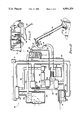
- FIG. 2 is a diagrammatic representation of a cleaning system embodying the invention.
- FIG. 3 is a diagrammatic representation of another cleaning system embodying another form of the invention.
- FIG. 1 Illustrated in FIG. 1 is a portable carpet and fabric cleaning system of the type commonly in use today.
- the system comprises a panel truck, or van, 11, a cleaning wand 12 coupled by means of hoses 13 and 14 to a cleaning liquid supply and retrieval unit housed in the truck.
- Hoses 13 and 14 may be stored on a reel 16.
- Truck 11 is provided with a door 17 to give access to the cleaning equipment.
- Wand 12 is provided at its distal end with a spray nozzle 18 which has cleaning liquid 19 supplied thereto under pressure via high pressure hose 13 (see FIG. 2).
- the wand 12 further includes a vacuum nozzle 20 adjoining the area of the surface to be cleaned which is subjected to the spray of cleaning liquid 19 from spray nozzle 18.
- Vacuum nozzle 20 is in communication with vacuum hose 14.
- the wand 12 is drawn across the surface to be cleaned so that a progressive area of the surface is subjected to a spray of hot cleaning liquid from nozzle 18.
- the cleaning liquid imparted to the surface is thereafter vacuumed by nozzle 20 to remove most of the cleaning liquid and any loosened soil from the surface.
- the flow of cleaning liquid 19 to nozzle 18 is controlled by the operator by means of a hand manipulated valve 21 in pressure hose 13 near the wand handle 22.
- the composition of the cleaning liquid 19 may vary depending upon the surface to be cleaned, but usually comprises a detergent and a surfactant admixed with water.
- the components of the cleaning liquid supply and retrieval unit 15 are illustrated diagrammatically in FIG. 2.
- This unit 15 is a multipurpose, air cooled, internal combustion engine 23. Energy to operate the engine 23 is supplied by any transportable fuel such as gasoline or propane.
- engine 23 One function performed by engine 23 is the pressurization and propelling of cleaning liquid through hose 13 to spray nozzle 18 on cleaning wand 12.
- the drive shaft 24 of engine 23 is connected by a belt drive 26 to a cleaning liquid pump 27.
- Pump 27 and associated piping constitute means for conveying cleaning liquid through first and second heat exchangers, designated 28 and 29, respectively, wherein the cleaning liquid is heated.
- Cleaning liquid enters heat exchanger 28 via an inlet conduit 31 from a supply source (not shown).
- the cleaning liquid is withdrawn from heat exchanger 28 through a low pressure pipe 32 by pump 27 and is conveyed in a high pressure pipe 33 to a coil 34 within heat exchanger 29.
- the heated cleaning liquid exits second heat exchanger 29 via high pressure hose 13 connected to cleaning wand 12.
- the second function performed by internal combustion engine 23 is to supply waste heat energy to heat the cleaning liquid passing through heat exchangers 28 and 29.
- Two sources of heat energy from engine 23 are utilized; the first source is heat in the cooling air exiting the engine and the second source is the heat in the exhaust gases exiting the engine.
- Internal combustion engine 23 is surrounded by a shroud 36 which functions as means for confining the cooling air passing over the engine and as means for conveying this cooling air away from the engine in a controlled manner.
- Heat is extracted from cooling air passing through shroud 36 and imparted to cleaning liquid in the first heat exchanger 28 by means of a heat pump which is also driven by engine 23.
- the heat pump includes a compressor 37 which is driven by a belt drive 38 coupled to the drive shaft 24 of engine 23.
- the heat pump also includes a condenser 39 associated with the first heat exchanger 28, an expansion device 41 and an evaporator 42 associated with the shroud 3 conveying cooling air away from the engine 23.
- the heat pump compressor 37, condenser 39, expansion device 41 and evaporator 42 are connected in a closed loop by tubing and charged with a suitable refrigerant, such as trichlorofluoromethane.
- a suitable refrigerant such as trichlorofluoromethane.
- gaseous refrigerant compressed by the compressor 37 is condensed in condenser 39 giving up its heat of condensation to cleaning liquid in heat exchanger 28.
- the liquid refrigerant next passes through expansion device 41 into a low pressure portion of the heat pump circuit which includes evaporator 42.
- the refrigerant absorbs heat from the engine cooling air as the latter passes over the evaporator. This causes evaporation of the refrigerant which is drawn into and compressed by the engine driven compressor 37. In this manner heat energy is transferred from the engine cooling air to the cleaning liquid passing through heat exchanger 28.
- the principal advantage to employing a heat pump to extract heat from the engine cooling air is that this makes it possible to substantially reduce the temperature of exiting cooling air below the temperature to which the cleaning liquid is being heated in first heat exchanger 28. With a properly balanced system the engine cooling air can be reduced in temperature to ambient air temperature so that the cooling air does not heat up the interior of the truck 11 when the system is operated.
- the hot cooling air conveyed away from engine 23 may be cooled by evaporator 42 back to 80° F.
- the heat thus extracted is released by condenser 39 into heat exchanger 28 to heat the cleaning liquid therein to around 140° F.
- the exhaust gases from engine 23 provide a second source of heat energy to further heat the cleaning liquid in heat exchanger 29 after the liquid has been preheated in heat exchanger 28.
- the engine 23 is equipped with an exhaust pipe 43 which functions as means for conveying exhaust gases away from the engine.
- the exhaust pipe 43 is associated with and communicates with the interior of heat exchanger 29.
- Hot exhaust gases which may be of the order of 600° F. to 1200° F., passing over coil 34 in heat exchanger 29 heat the cleaning liquid to a temperature of from 180° F. to 200° F. which is sufficiently hot to provide good cleaning action by the cleaning liquid.
- all of the heating is provided without using any auxiliary heater such as the oil fired heater required in some cleaning systems.
- the final function performed by internal combustion engine 23 is the creation of a vacuum to draw cleaning liquid, air and soil into the vacuum nozzle 20 on wand 12 and to convey the waste cleaning liquid and soil to a waste storage tank 44.
- Engine 23 drives a vacuum pump 46 through a belt drive 47 working off of drive shaft 24.
- Vacuum pump 46 is in communication with the interior of waste tank 44 through pipe 48.
- the vacuum created within tank 44 draws the air/waste cleaning liquid/soil mixture through vacuum hose 14 into tank 44 where most of the cleaning liquid and soil separate from the air which is drawn into the vacuum pump 46.
- the air expelled from vacuum pump 46 through discharge pipe 49 contains heat which can be employed in the cleaning water heating circuit. Much of this heat is imparted to the air during the period when the air is admixed with waste cleaning liquid in vacuum hose 14. Additional heat is imparted to the air when it is compressed in vacuum pump 46.
- By directing air discharge pipe 49 to the evaporator 42 of the heat pump the heat in the discharge air can be extracted by the evaporator and conveyed to the first heat exchanger 28 in the cleaning liquid heating circuit in the same manner as heat is extracted and delivered from the cooling air from the engine.
- a muffler 51 and a liquid separator 52 may be interposed in discharge air pipe 49.
- the muffler 51 reduces emission of noise from vacuum pump 46.
- the separator 52 functions to recover any liquid remaining in the exhaust air to insure that it will not accumulate and possibly freeze on evaporator 42.
- FIG. 3 illustrates another mode for carrying out the invention.
- Components of the cleaning liquid supply and retrieval unit in FIG. 3 which function in the same manner as the components of the unit shown in FIG. 2 are identified by like reference numerals.
- the FIG. 3 unit employs a cleaning wand 12 to which heated cleaning liquid is supplied by a high pressure hose 13 and from which air, spent cleaning liquid and soil are withdrawn through a vacuum hose 14.
- the unit shown in FIG. 3 preferably employs a liquid cooled internal combustion engine 60.
- Engine 60 performs several functions by driving several different pumps.
- Through belt drive 26 engine 60 drives cleaning liquid pump 27.
- the pump 27 withdraws cleaning liquid from a source (not shown) through a pipe 61 and forces the liquid through a pipe 62 which passes through first and second heat exchangers 63 and 64, respectively, and which then connects with high pressure wand hose 13.
- Vacuum pump 46 is in communication with the interior of waste storage tank 44 through pipe 48.
- the vacuum created in tank 44 draws the air/waste cleaning liquid/soil mixture through vacuum hose 14 into tank 44 where most of the cleaning liquid and soil separate from the air and are retained in the tank.
- the air expelled from vacuum pump 46 through discharge pipe 49 contains a considerable amount of heat, particularly heat generated by the compressive action of the vacuum pump 46.
- air may enter vacuum pump at around 120° F.-130° F. and exit it at the temperature of around 200° F.
- This air after passing through muffler 51 and separator 52, flows through a continuation of discharge pipe 49 to the first heat exchanger 63 where the heat therein can be imparted to the cleaning liquid flowing through pipe 61.
- the cleaning liquid is also heated in first heat exchanger 43 by heat from the exhaust gases of the internal combustion engine 60. This is preferably accomplished by conveying these gases through an exhaust pipe 43 to an air mixing chamber 66 in communication with the interior of first heat exchanger 63. Vacuum pump discharge pipe 49 also communicates with mixing chamber 66. Thus, air leaving vacuum pump 46 and engine exhaust gases flowing through exhaust pipe 43 are brought together in mixing chamber 66 and the quantities of heat therein are combined before entering heat exchanger 63.
- Exhaust gases from engine 60 may be at a temperature of 1000° to 1200° F. Air leaving the vacuum pump 46 will normally have a temperature of around 200° F. When these two gases are mixed the resulting mixture will have a temperature of something less than exhaust gas temperature and greater than vacuum pump discharge gas temperature.
- the mixture entering heat exchanger 63 is within a temperature range of about 375° F. to 400° F. This gas mixture passing through heat exchanger 63 preferably is capable of heating 70° F. cleaning liquid to a temperature of 140° F. to 150° F.
- the mixing chamber 66 can be equipped with a flow control valve 67 for adjusting the relative quantities of exhaust gases and pump discharge air entering heat exchanger 63. And this may include bypassing some of either of these gases through a discharge port 68.
- Heat exchanger 64 Secondary heating of cleaning liquid to the desired cleaning range of 170° to 200° F. is accomplished in heat exchanger 64 utilizing heat extracted from engine 60 via a cooling system. That system includes a coolant pump 69 driven by engine 60 through a belt drive 70. Pump 69 moves liquid coolant through a circuit of pipes 71 from around the cylinders (not shown) of engine 60 through second heat exchanger 64 and back to the engine 60. Any heat losses in coolant pump 69 are imparted to the circulating coolant and are available to heat the cleaning liquid in heat exchanger 64.
Abstract
Description
Claims (9)
Priority Applications (1)
| Application Number | Priority Date | Filing Date | Title |
|---|---|---|---|
| US07/519,000 US4991254A (en) | 1988-12-19 | 1990-05-04 | Cleaning system |
Applications Claiming Priority (2)
| Application Number | Priority Date | Filing Date | Title |
|---|---|---|---|
| US07/286,616 US4940082A (en) | 1988-12-19 | 1988-12-19 | Cleaning system |
| US07/519,000 US4991254A (en) | 1988-12-19 | 1990-05-04 | Cleaning system |
Related Parent Applications (1)
| Application Number | Title | Priority Date | Filing Date |
|---|---|---|---|
| US07/286,616 Continuation-In-Part US4940082A (en) | 1988-12-19 | 1988-12-19 | Cleaning system |
Publications (1)
| Publication Number | Publication Date |
|---|---|
| US4991254A true US4991254A (en) | 1991-02-12 |
Family
ID=26963958
Family Applications (1)
| Application Number | Title | Priority Date | Filing Date |
|---|---|---|---|
| US07/519,000 Expired - Lifetime US4991254A (en) | 1988-12-19 | 1990-05-04 | Cleaning system |
Country Status (1)
| Country | Link |
|---|---|
| US (1) | US4991254A (en) |
Cited By (32)
| Publication number | Priority date | Publication date | Assignee | Title |
|---|---|---|---|---|
| US5095578A (en) * | 1991-02-12 | 1992-03-17 | Steamatic, Inc. | Vacuum system for cleaning apparatus |
| US5165139A (en) * | 1992-02-03 | 1992-11-24 | Tecnically Engineered Cleaning Hydraulic Systems | Mobile cleaning unit |
| US5371918A (en) * | 1993-05-05 | 1994-12-13 | Shero; William K. | Water heater for carpet cleaning systems |
| US5377628A (en) * | 1992-12-15 | 1995-01-03 | Adams; Joseph S. | Exhaust cooling system |
| US5463791A (en) * | 1994-09-01 | 1995-11-07 | Redfield Engineering | Surface cleaning appliance |
| US5469598A (en) * | 1994-01-26 | 1995-11-28 | Sales; John K. | Mobile system cleaning apparatus |
| US6032326A (en) * | 1998-11-06 | 2000-03-07 | Professional Chemicals Corporation | Surface cleaning appliance |
| ES2141633A1 (en) * | 1994-06-24 | 2000-03-16 | Vetrella Spa | Multifunctional cleaner for domestic use |
| WO2000035329A2 (en) * | 1998-12-17 | 2000-06-22 | York Shawn L | Portable, high-temperature, high-pressure washing plant |
| US6216312B1 (en) * | 1998-04-21 | 2001-04-17 | Aussie Red Equipment Pty. Ltd. | Cleaning apparatus |
| AU752144B2 (en) * | 1998-07-27 | 2002-09-05 | Steamvac of Australia Pty. Ltd. | Steam cleaning heating unit |
| US6517639B2 (en) * | 1998-10-14 | 2003-02-11 | Alfred Kaercher Gmbh & Co. | Method and device for decontaminating interior spaces |
| US6675437B1 (en) | 1999-12-15 | 2004-01-13 | Shawn L. York | Portable high-temperature, high-pressure washing plant |
| US20040089734A1 (en) * | 2002-11-06 | 2004-05-13 | Martin Timothy R. | Vehicle engine powered high pressure water sewer clearing apparatus and method |
| US20040134649A1 (en) * | 2003-01-14 | 2004-07-15 | Paul Richardson | Carpet cleaning system |
| US20040226584A1 (en) * | 2003-05-14 | 2004-11-18 | Michael Guest | Multifunctional surface cleaning machine and method of using the same |
| GB2423240A (en) * | 2005-02-17 | 2006-08-23 | Bissell Homecare Inc | Surface cleaning apparatus with cleaning fluid supply |
| US20070061996A1 (en) * | 2005-09-17 | 2007-03-22 | Hydramaster Corporation | Heat exchanger |
| US20070095370A1 (en) * | 2005-11-03 | 2007-05-03 | Vladimir Kratser | Mobile high-temperature washing plant |
| US7216397B1 (en) | 2003-08-13 | 2007-05-15 | Paul Tanner | Collection tank and associated cleaning system |
| US20080035304A1 (en) * | 2006-08-11 | 2008-02-14 | Castle Rock Industries, Inc. | Truck mounted heat exchange device |
| US20100294459A1 (en) * | 2009-05-21 | 2010-11-25 | Ron Williams | Heat exchange configuration for use in a mobile system cleaning apparatus |
| US8056182B2 (en) | 2005-08-30 | 2011-11-15 | Tacony Corporation | Heating system for a portable carpet extractor |
| USD654234S1 (en) | 2010-12-08 | 2012-02-14 | Karcher North America, Inc. | Vacuum bag |
| WO2012010118A3 (en) * | 2010-06-10 | 2012-11-08 | Norbert Fischer | Device and method removing dirt |
| US20140082880A1 (en) * | 2009-02-09 | 2014-03-27 | Sapphire Scientific | Systems and methods for transferring heat and/or sound during fluid extraction and/or cleaning processes |
| US8887340B2 (en) | 2003-05-14 | 2014-11-18 | Kärcher North America, Inc. | Floor cleaning apparatus |
| US9015887B1 (en) | 2003-05-14 | 2015-04-28 | Kärcher North America, Inc. | Floor treatment apparatus |
| US9351622B2 (en) | 2012-09-04 | 2016-05-31 | Sapphire Scientific Inc. | Fluid extracting device with shaped head and associated systems and methods of use and manufacture |
| US10060641B2 (en) | 2015-02-25 | 2018-08-28 | Dri-Eaz Products, Inc. | Systems and methods for drying roofs |
| USD907868S1 (en) | 2019-01-24 | 2021-01-12 | Karcher North America, Inc. | Floor cleaner |
| CN114151192A (en) * | 2021-12-16 | 2022-03-08 | 中国船舶重工集团公司第七一一研究所 | Cleaning device |
Citations (10)
| Publication number | Priority date | Publication date | Assignee | Title |
|---|---|---|---|---|
| US3594849A (en) * | 1967-10-13 | 1971-07-27 | Chester L Coshow | Cleaning apparatus |
| US4109340A (en) * | 1977-01-27 | 1978-08-29 | Bates Leonard Eugene | Truck mounted carpet cleaning machine |
| US4158248A (en) * | 1977-02-14 | 1979-06-19 | Palmer Michael C | Mobile cleaning unit |
| US4284127A (en) * | 1979-06-01 | 1981-08-18 | Syd W. Collier Company Limited | Carpet cleaning systems |
| US4336627A (en) * | 1980-05-19 | 1982-06-29 | Bascus Lionel D | Water conditioning systems |
| US4443909A (en) * | 1981-09-08 | 1984-04-24 | Cameron James D | Carpet cleaning system |
| US4593753A (en) * | 1984-11-09 | 1986-06-10 | Mcconnell Research Enterprises Pty. Ltd. | Exhaust gas liquid heating system for internal combustion engines |
| US4803446A (en) * | 1985-03-28 | 1989-02-07 | New Japan Radio Co., Ltd. | Low noise microwave amplifier |
| US4862551A (en) * | 1989-02-28 | 1989-09-05 | Martinez Donald L | Self-contained cleaning system |
| US4949424A (en) * | 1989-01-23 | 1990-08-21 | William Shero | Carpet cleaning system |
-
1990
- 1990-05-04 US US07/519,000 patent/US4991254A/en not_active Expired - Lifetime
Patent Citations (10)
| Publication number | Priority date | Publication date | Assignee | Title |
|---|---|---|---|---|
| US3594849A (en) * | 1967-10-13 | 1971-07-27 | Chester L Coshow | Cleaning apparatus |
| US4109340A (en) * | 1977-01-27 | 1978-08-29 | Bates Leonard Eugene | Truck mounted carpet cleaning machine |
| US4158248A (en) * | 1977-02-14 | 1979-06-19 | Palmer Michael C | Mobile cleaning unit |
| US4284127A (en) * | 1979-06-01 | 1981-08-18 | Syd W. Collier Company Limited | Carpet cleaning systems |
| US4336627A (en) * | 1980-05-19 | 1982-06-29 | Bascus Lionel D | Water conditioning systems |
| US4443909A (en) * | 1981-09-08 | 1984-04-24 | Cameron James D | Carpet cleaning system |
| US4593753A (en) * | 1984-11-09 | 1986-06-10 | Mcconnell Research Enterprises Pty. Ltd. | Exhaust gas liquid heating system for internal combustion engines |
| US4803446A (en) * | 1985-03-28 | 1989-02-07 | New Japan Radio Co., Ltd. | Low noise microwave amplifier |
| US4949424A (en) * | 1989-01-23 | 1990-08-21 | William Shero | Carpet cleaning system |
| US4862551A (en) * | 1989-02-28 | 1989-09-05 | Martinez Donald L | Self-contained cleaning system |
Cited By (54)
| Publication number | Priority date | Publication date | Assignee | Title |
|---|---|---|---|---|
| US5095578A (en) * | 1991-02-12 | 1992-03-17 | Steamatic, Inc. | Vacuum system for cleaning apparatus |
| US5165139A (en) * | 1992-02-03 | 1992-11-24 | Tecnically Engineered Cleaning Hydraulic Systems | Mobile cleaning unit |
| US5377628A (en) * | 1992-12-15 | 1995-01-03 | Adams; Joseph S. | Exhaust cooling system |
| US5371918A (en) * | 1993-05-05 | 1994-12-13 | Shero; William K. | Water heater for carpet cleaning systems |
| US5469598A (en) * | 1994-01-26 | 1995-11-28 | Sales; John K. | Mobile system cleaning apparatus |
| ES2141633A1 (en) * | 1994-06-24 | 2000-03-16 | Vetrella Spa | Multifunctional cleaner for domestic use |
| US5463791A (en) * | 1994-09-01 | 1995-11-07 | Redfield Engineering | Surface cleaning appliance |
| US6216312B1 (en) * | 1998-04-21 | 2001-04-17 | Aussie Red Equipment Pty. Ltd. | Cleaning apparatus |
| AU752144B2 (en) * | 1998-07-27 | 2002-09-05 | Steamvac of Australia Pty. Ltd. | Steam cleaning heating unit |
| US6517639B2 (en) * | 1998-10-14 | 2003-02-11 | Alfred Kaercher Gmbh & Co. | Method and device for decontaminating interior spaces |
| US6032326A (en) * | 1998-11-06 | 2000-03-07 | Professional Chemicals Corporation | Surface cleaning appliance |
| WO2000035329A3 (en) * | 1998-12-17 | 2000-09-14 | Shawn L York | Portable, high-temperature, high-pressure washing plant |
| WO2000035329A2 (en) * | 1998-12-17 | 2000-06-22 | York Shawn L | Portable, high-temperature, high-pressure washing plant |
| US6675437B1 (en) | 1999-12-15 | 2004-01-13 | Shawn L. York | Portable high-temperature, high-pressure washing plant |
| US20040089734A1 (en) * | 2002-11-06 | 2004-05-13 | Martin Timothy R. | Vehicle engine powered high pressure water sewer clearing apparatus and method |
| US20040134649A1 (en) * | 2003-01-14 | 2004-07-15 | Paul Richardson | Carpet cleaning system |
| US9015887B1 (en) | 2003-05-14 | 2015-04-28 | Kärcher North America, Inc. | Floor treatment apparatus |
| US8887340B2 (en) | 2003-05-14 | 2014-11-18 | Kärcher North America, Inc. | Floor cleaning apparatus |
| US10555657B2 (en) | 2003-05-14 | 2020-02-11 | Kärcher North America, Inc. | Floor treatment apparatus |
| US9757005B2 (en) | 2003-05-14 | 2017-09-12 | Kärcher North America, Inc. | Floor treatment apparatus |
| US9730566B2 (en) | 2003-05-14 | 2017-08-15 | Kärcher North America, Inc. | Floor treatment apparatus |
| US9510721B2 (en) | 2003-05-14 | 2016-12-06 | Karcher North America, Inc. | Floor cleaning apparatus |
| US9451861B2 (en) | 2003-05-14 | 2016-09-27 | Kärcher North America, Inc. | Floor treatment apparatus |
| US7406739B2 (en) | 2003-05-14 | 2008-08-05 | Karcher Floor Care, Inc | Grout tool for use with an all surface cleaning apparatus |
| US9192276B2 (en) | 2003-05-14 | 2015-11-24 | Karcher North America, Inc. | Floor cleaning apparatus |
| US20060037171A1 (en) * | 2003-05-14 | 2006-02-23 | Michael Guest | Grout tool for use with an all surface cleaning apparatus |
| US20040226584A1 (en) * | 2003-05-14 | 2004-11-18 | Michael Guest | Multifunctional surface cleaning machine and method of using the same |
| US7216397B1 (en) | 2003-08-13 | 2007-05-15 | Paul Tanner | Collection tank and associated cleaning system |
| US7784148B2 (en) | 2005-02-17 | 2010-08-31 | Bissell Homecare, Inc. | Surface cleaning apparatus with cleaning fluid supply |
| US20060288518A1 (en) * | 2005-02-17 | 2006-12-28 | Bissell Homecare, Inc. | Surface cleaning apparatus with cleaning fluid supply |
| US7979951B2 (en) | 2005-02-17 | 2011-07-19 | Bissell Homecare, Inc. | Surface cleaning apparatus with recovery tank |
| US7979955B2 (en) | 2005-02-17 | 2011-07-19 | Bissell Homecare, Inc. | Surface cleaning apparatus with recovery tank |
| GB2423240A (en) * | 2005-02-17 | 2006-08-23 | Bissell Homecare Inc | Surface cleaning apparatus with cleaning fluid supply |
| US7966690B2 (en) | 2005-02-17 | 2011-06-28 | Bissell Homecare, Inc. | Surface cleaning with recovery tank float control |
| GB2423240B (en) * | 2005-02-17 | 2008-10-22 | Bissell Homecare Inc | Surface cleaning apparatus with cleaning fluid supply |
| US8505155B2 (en) | 2005-02-17 | 2013-08-13 | Bissell Homecare, Inc. | Surface cleaning apparatus with recovery tank latch |
| US8056182B2 (en) | 2005-08-30 | 2011-11-15 | Tacony Corporation | Heating system for a portable carpet extractor |
| US8032979B2 (en) * | 2005-09-17 | 2011-10-11 | Hydramaster North America, Inc. | Heat exchanger |
| US20070061996A1 (en) * | 2005-09-17 | 2007-03-22 | Hydramaster Corporation | Heat exchanger |
| US20070095370A1 (en) * | 2005-11-03 | 2007-05-03 | Vladimir Kratser | Mobile high-temperature washing plant |
| US20080035304A1 (en) * | 2006-08-11 | 2008-02-14 | Castle Rock Industries, Inc. | Truck mounted heat exchange device |
| US7841042B2 (en) | 2006-08-11 | 2010-11-30 | Karcher North America, Inc. | Truck mounted heat exchange device |
| US20140082880A1 (en) * | 2009-02-09 | 2014-03-27 | Sapphire Scientific | Systems and methods for transferring heat and/or sound during fluid extraction and/or cleaning processes |
| US9332887B2 (en) * | 2009-02-09 | 2016-05-10 | Sapphire Scientific | Systems and methods for transferring heat and/or sound during fluid extraction and/or cleaning processes |
| US20100294459A1 (en) * | 2009-05-21 | 2010-11-25 | Ron Williams | Heat exchange configuration for use in a mobile system cleaning apparatus |
| US8458852B2 (en) | 2009-05-21 | 2013-06-11 | Kärcher North America, Inc. | Heat exchange configuration for use in a mobile system cleaning apparatus |
| WO2012010118A3 (en) * | 2010-06-10 | 2012-11-08 | Norbert Fischer | Device and method removing dirt |
| USD654234S1 (en) | 2010-12-08 | 2012-02-14 | Karcher North America, Inc. | Vacuum bag |
| US9351622B2 (en) | 2012-09-04 | 2016-05-31 | Sapphire Scientific Inc. | Fluid extracting device with shaped head and associated systems and methods of use and manufacture |
| US10060641B2 (en) | 2015-02-25 | 2018-08-28 | Dri-Eaz Products, Inc. | Systems and methods for drying roofs |
| US10753628B2 (en) | 2015-02-25 | 2020-08-25 | Legend Brands, Inc. | Systems and methods for drying roofs |
| US11686482B2 (en) | 2015-02-25 | 2023-06-27 | Legend Brands, Inc. | Systems and methods for drying roofs |
| USD907868S1 (en) | 2019-01-24 | 2021-01-12 | Karcher North America, Inc. | Floor cleaner |
| CN114151192A (en) * | 2021-12-16 | 2022-03-08 | 中国船舶重工集团公司第七一一研究所 | Cleaning device |
Similar Documents
| Publication | Publication Date | Title |
|---|---|---|
| US4991254A (en) | Cleaning system | |
| US4940082A (en) | Cleaning system | |
| US5469598A (en) | Mobile system cleaning apparatus | |
| US8032979B2 (en) | Heat exchanger | |
| US4109340A (en) | Truck mounted carpet cleaning machine | |
| EP0365351B1 (en) | Method and apparatus for operating a refrigeration system | |
| EP0045144B1 (en) | Heat pump systems for residential use | |
| CN107893715B (en) | Intake and exhaust system of internal combustion engine | |
| EP0859136A1 (en) | Gas turbine with energy recovering | |
| US6334436B1 (en) | Secondary air system for an internal combustion engine | |
| CN103080523B (en) | Engine arrangement comprising a heat recovery circuit and an exhaust gases after-treatment system | |
| JPH11506181A (en) | Combined cycle power plant using liquefied natural gas (LNG) and gas turbine plant using LNG as fuel | |
| US6182328B1 (en) | Mobile cleaning system | |
| US4513572A (en) | Method of recovering energy in a power generator and power generator for carrying out the said method | |
| US5537974A (en) | Method and apparatus for using exhaust gas condenser to reclaim and filter expansion fluid which has been mixed with combustion gas in combined cycle heat engine expansion process | |
| CA2110937C (en) | Exhaust cooling system | |
| CN100434836C (en) | Water cooling type engine heat pump | |
| JPH06207755A (en) | Air type freezing cycle device | |
| EP0397760B1 (en) | Method and apparatus for recovery of refrigerant | |
| US20070204962A1 (en) | Accelerated flameless evaporation system | |
| JPH08193504A (en) | Combined-cycle of power plant | |
| JPS6438129A (en) | Dehumidifying apparatus with ice heat accumulating function | |
| JPS6040800A (en) | Vacuum system | |
| IL114123A (en) | Gas turbine system with heat recovery cycle and method for using the same | |
| JPH0328676A (en) | Refrigerant recovery equipment |
Legal Events
| Date | Code | Title | Description |
|---|---|---|---|
| AS | Assignment |
Owner name: PROFESSIONAL CHEMICALS CORPORATION, ARIZONA Free format text: ASSIGNMENT OF ASSIGNORS INTEREST.;ASSIGNORS:RODEN, JAMES R.;RODEN, MICHAEL R.;REEL/FRAME:005301/0421 Effective date: 19900426 |
|
| STCF | Information on status: patent grant |
Free format text: PATENTED CASE |
|
| FEPP | Fee payment procedure |
Free format text: PAYOR NUMBER ASSIGNED (ORIGINAL EVENT CODE: ASPN); ENTITY STATUS OF PATENT OWNER: SMALL ENTITY |
|
| FEPP | Fee payment procedure |
Free format text: PAYMENT IS IN EXCESS OF AMOUNT REQUIRED. REFUND SCHEDULED (ORIGINAL EVENT CODE: F169); ENTITY STATUS OF PATENT OWNER: SMALL ENTITY |
|
| FEPP | Fee payment procedure |
Free format text: PAT HLDR NO LONGER CLAIMS SMALL ENT STAT AS SMALL BUSINESS (ORIGINAL EVENT CODE: LSM2); ENTITY STATUS OF PATENT OWNER: SMALL ENTITY |
|
| FPAY | Fee payment |
Year of fee payment: 4 |
|
| FEPP | Fee payment procedure |
Free format text: PAYER NUMBER DE-ASSIGNED (ORIGINAL EVENT CODE: RMPN); ENTITY STATUS OF PATENT OWNER: SMALL ENTITY Free format text: PAT HOLDER CLAIMS SMALL ENTITY STATUS - SMALL BUSINESS (ORIGINAL EVENT CODE: SM02); ENTITY STATUS OF PATENT OWNER: SMALL ENTITY |
|
| FPAY | Fee payment |
Year of fee payment: 8 |
|
| FEPP | Fee payment procedure |
Free format text: PAYOR NUMBER ASSIGNED (ORIGINAL EVENT CODE: ASPN); ENTITY STATUS OF PATENT OWNER: SMALL ENTITY |
|
| AS | Assignment |
Owner name: FLEET NATIONAL BANK, MASSACHUSETTS Free format text: ASSIGNMENT OF ASSIGNORS INTEREST;ASSIGNOR:PROFESSIONAL CHEMICALS CORPORATION;REEL/FRAME:010776/0371 Effective date: 20000418 |
|
| AS | Assignment |
Owner name: FLEET NATIONAL BANK, AS AGENT, MASSACHUSETTS Free format text: RE-RECORD TO CORRECT THE BRIEF ON THE COVER SHEET, PREVIOUSLY RECORDED AT REEL 010776, FRAME 0371.;ASSIGNOR:PROFESSIONAL CHEMICALS CORPORATION;REEL/FRAME:011103/0486 Effective date: 20000418 |
|
| AS | Assignment |
Owner name: PROFESSIONAL CHEMICALS CORPORATION, ARIZONA Free format text: ASSIGNMENT OF ASSIGNORS INTEREST;ASSIGNOR:FLEET NATIONAL BANK, AS AGENT;REEL/FRAME:012795/0019 Effective date: 20020328 |
|
| AS | Assignment |
Owner name: FLEET NATIONAL BANK, AS AGENT, MASSACHUSETTS Free format text: SECURITY INTEREST;ASSIGNOR:PROFESSIONAL CHEMICALS CORPORATION;REEL/FRAME:012865/0502 Effective date: 20020328 |
|
| FPAY | Fee payment |
Year of fee payment: 12 |
|
| REMI | Maintenance fee reminder mailed | ||
| AS | Assignment |
Owner name: CASTLE ROCK INDUSTRIES, INC., COLORADO Free format text: ASSIGNMENT OF ASSIGNORS INTEREST;ASSIGNOR:PROFESSIONAL CHEMICALS CORPORATION;REEL/FRAME:015293/0159 Effective date: 20040412 |
|
| AS | Assignment |
Owner name: HARRIS TRUST AND SAVINGS BANK, AS ADMINISTRATIVE A Free format text: SECURITY AGREEMENT;ASSIGNOR:PROFESSIONAL CHEMICALS CORPORATION;REEL/FRAME:015509/0283 Effective date: 20040602 |
|
| AS | Assignment |
Owner name: PROFESSIONAL CHEMICALS CORPORATION, COLORADO Free format text: RELEASE BY SECURED PARTY;ASSIGNOR:FLEET NATIONAL BANK, AS AGENT;REEL/FRAME:015541/0286 Effective date: 20040614 |
|
| AS | Assignment |
Owner name: KARCHER FLOOR CARE, INC., COLORADO Free format text: CHANGE OF NAME;ASSIGNOR:CASTLE ROCK INDUSTRIES, INC.;REEL/FRAME:019795/0132 Effective date: 20070419 |
|
| AS | Assignment |
Owner name: KARCHER NORTH AMERICA, INC., COLORADO Free format text: MERGER;ASSIGNORS:KARCHER FLOOR CARE, INC.;KARCHER RESIDENTIAL SOLUTIONS, INC.;REEL/FRAME:022390/0283 Effective date: 20081231 |
|
| AS | Assignment |
Owner name: PROFESSIONAL CHEMICALS CORPORATION, COLORADO Free format text: RELEASE BY SECURED PARTY;ASSIGNOR:BMO HARRIS BANK N.A., SUCCESSOR TO HARRIS TRUST AND SAVINGS BANK;REEL/FRAME:041688/0188 Effective date: 20170322 |