US4991435A - Electronic fuel gauge system - Google Patents
Electronic fuel gauge system Download PDFInfo
- Publication number
- US4991435A US4991435A US07/402,377 US40237789A US4991435A US 4991435 A US4991435 A US 4991435A US 40237789 A US40237789 A US 40237789A US 4991435 A US4991435 A US 4991435A
- Authority
- US
- United States
- Prior art keywords
- liquid level
- current source
- slew rate
- level indicating
- indicating system
- Prior art date
- Legal status (The legal status is an assumption and is not a legal conclusion. Google has not performed a legal analysis and makes no representation as to the accuracy of the status listed.)
- Expired - Lifetime
Links
Images


Classifications
-
- G—PHYSICS
- G01—MEASURING; TESTING
- G01F—MEASURING VOLUME, VOLUME FLOW, MASS FLOW OR LIQUID LEVEL; METERING BY VOLUME
- G01F23/00—Indicating or measuring liquid level or level of fluent solid material, e.g. indicating in terms of volume or indicating by means of an alarm
- G01F23/80—Arrangements for signal processing
- G01F23/806—Particular electronic circuits for handling non-digital processing equipment
Definitions
- the present invention relates generally to a liquid level indicating system and, more particularly, to such a system for monitoring liquid level variations produced by consumption of the liquid substantially independent of relatively rapid variations in the liquid level due to unavoidable transient disturbances.
- the system is particularly applicable to measuring the fuel level in a motor vehicle fuel tank and accordingly will be described with reference to this application herein.
- a basic gauge system includes a liquid level sensor in the fuel tank and a gauge connected to indicate to the driver the status of the sensor unit and therefor the fuel level.
- a variety of damping arrangements have been incorporated into the gauge systems to eliminate rapid transient movements of the fuel gauge due to fuel slosh so that the driver can accurately monitor vehicle fuel level. Damping arrangements include mechanical damping devices associated with the level sensor in the fuel tank, the fuel level gauge or both. More commonly in modern gauge systems, electrical damping circuitry is provided.
- an improved liquid level indicating system is needed which will provide a consistent damping characteristic and be simple and inexpensive to produce and service.
- the improved system will facilitate production of the damping circuitry as an integrated circuit to still further reduce costs, ease production and service, and add to the versatility of the system.
- the liquid level indicating system of the present invention which includes an anti-slosh feature incorporated into a system amplifier to substantially eliminate fluctuations in the fuel level indicated by a fuel gauge driven by the amplifier.
- the anti-slosh feature is provided by limiting the slew rate of the amplifier during normal operation of the system.
- the slew rate is limited by using a limited current source to provide dc bias current within the amplifier. Accordingly, while the input to the amplifier can change at any rate, the output can change only at the limited slew rate which is set by the limited current source.
- the normally limited current source is supplemented by a secondary current source which Provides substantially higher dc bias current within the amplifier and accordingly a substantially higher slew rate for the amplifier.
- the secondary current source is activated for a defined period of time to allow the fuel gauge to initialize, and then is disabled such that the amplifier is slew rate limited to correct for fuel slosh.
- Amplification means are interconnected between the sensor and the gauge for amplifying the signal, with the amplification means being slew rate limited to substantially eliminate the rapid variations from the signal.
- the liquid level indicating system is typically activated by switch means, such as a motor vehicle ignition switch, for selectively powering the system.
- switch means such as a motor vehicle ignition switch
- the amplification means comprises slew rate control means for changing the slew rate of the amplification means to rapidly initialize the fuel gauge upon activation of the switch means.
- the slew rate control means may comprise first and second current source means for setting dc bias current within the amplification means.
- the first current source means limits current to set the slew rate of the amplification means at a level which substantially eliminates the rapid variations in the signal and the second current source means provides additional dc bias current to increase the slew rate for rapid initialization of the fuel gauge of the system.
- Timer means may be provided for enabling the second current source means for a selected period of time upon activation of the switch means.
- the timer means may comprise a timer circuit or a resistor-capacitor (RC) circuit and a comparator circuit.
- the amplification means including the first current source means and the second current source means may be combined into an integrated circuit.
- the timer means, the amplification means, the first current source means and the second current source means are combined into an integrated circuit.
- a liquid level indicating system comprises a sensor for generating a signal having a magnitude corresponding to the liquid level and a liquid level signaling gauge.
- Amplification means are interconnected between the sensor and the gauge for amplifying the signal.
- First current source means provides dc bias current within the amplification means with the first current source means being limited to a defined current to thereby limit the slew rate of the amplification means to substantially eliminate transient variations in the amplified signal resulting from sloshing of the liquid.
- the system may further comprise second current source means for providing supplemental dc bias current within the amplification means with the second current source means providing sufficient current to substantially increase the slew rate of the amplification means for initialization of the gauge upon power up of the liquid level indicating system.
- Timer means enable the second current source means for a defined initialization time period upon power up of the liquid level indicating system and thereafter disable the second current source means.
- the amplification means, the first current source means and the second current source means may be combined into an integrated circuit.
- the timer means, the amplification means, the first current source means and the second current source means are combined into an integrated circuit.
- Slew rate control means are coupled to the amplification means for limiting the slew rate of the amplification means to substantially eliminate the rapid variations from the amplified signal.
- the slew rate control means may comprise first and second current source means for setting dc bias current within the amplification means, the first current source means limiting current to a level to set the slew rate of the amplification means at a level to substantially eliminate the rapid variations from the amplified signal and the second current source means providing additional current to increase the slew rate for rapid initialization of the liquid level indicating system.
- an object of the present invention to provide an improved liquid level indicating system which includes an anti-slosh feature coupled to a system amplifier connected between a liquid level sensor and a liquid level indicating gauge to substantially eliminate fluctuations in the level indicated by the gauge; to provide an improved liquid level indicating system which includes an anti-slosh feature provided by limiting the slew rate of an amplifier connected between a liquid level sensor and a liquid level indicating gauge to substantially eliminate fluctuations in the level indicated by the gauge; to provide an improved liquid level indicating system which includes an anti-slosh feature provided by setting dc bias current within an amPlifier connected between a liquid level sensor and a liquid level indicating gauge via a first limited current source to limit the slew rate of the amplifier and thereby substantially eliminate fluctuations in the level indicated by the gauge; and, to provide an improved liquid level indicating system which includes an anti-slosh feature provided by limiting dc bias current within an amplifier connected between a liquid level sensor and a liquid level indicating gauge via a first limited current
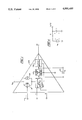
- FIG. 1 is a schematic block diagram of an operational amplifier including selective slew rate control particularly applicable to an electronic fuel gauge system in accordance with the present invention
- FIGS. 2 and 3 are schematic block diagrams of two embodiments of electronic fuel gauge systems in accordance with the present invention illustrating an integrated circuit which includes the operational amplifier of FIG. 1 and associated timer circuitry to further adapt that amplifier for use is such electronic fuel gauge systems;
- FIG. 4 shows a resistor-capacitor (RC) circuit which will be analyzed hereinafter.
- FIGS. 2 and 3 Two of a number of possible alternative embodiments of a liquid level indicating system 100 in accordance with the present invention are shown in FIGS. 2 and 3.
- the system 100 is intended for use in an environment in which the liquid level is subjected to relatively rapid variations compared to the variations which are to be monitored by the system. While generally applicable for measuring liquid levels, the system 100 is Particularly applicable for measuring fuel levels in a motor vehicle and accordingly will be described with reference to this application.
- the system 100 comprises a sensor 102 for generating a signal representative of the fuel level within a vehicle tank (not shown) and a fuel level signaling gauge 104.
- Amplification means comprising the operational amplifier 106 in the illustrated embodiments and shown in detail in FIG. 1, is interconnected between the sensor 102 and the gauge 104 for amplifying the signal generated by the sensor 102.
- the amplifier 106 is slew rate limited to substantially eliminate rapid variations in the signal generated by the sensor 102 by fuel slosh due to the normal operating movements of the vehicle before the signal is applied to the gauge 104.
- the slew rate of an amplifier is the rate at which the amplifier can change or swing its output voltage level.
- the slew rate is determined by the current available to charge capacitance within and associated with the amplifier, for example the current available from the input stage of an operational amplifier and the amplifier compensation capacitor.
- the operational amplifier 106 is structured in accordance with well known analog/integrated circuit technology and includes an output amplifier stage 108, voltage gain and output driver stage 110 and differential input amplifier stage 112.
- a compensation capacitor 114 is externally connected to the amplifier 106 also in a conventional manner.
- the operational amplifier 106 includes slew rae control means comprising first and second current source means for setting dc bias currents within the amplifier 106 and in particular within the input amplifier stage 112.
- the first current source means comprises a current source circuit 116 which limits dc bias current within the input amplifier stage 112 of the amplifier 106.
- the rate at which the limited dc bias current from the current source circuit 116 charges the compensation capacitor 114 and any other parasitic capacitance within the circuit determines the slew rate of the amplifier 106.
- the slew rate is set by the current source 116 (and the selection of the capacitor 114) at a level which substantially eliminates the rapid variations in the signal generated by the sensor 102.
- the second current source means comprises a current source circuit 118 which provides additional dc bias current to increase the slew rate for rapid initialization of the gauge 104 and hence the liquid level indicating system 100. It is noted that the second current source circuit 118 is preferred for the motor vehicle application, but is not required for all applications of the present invention, such as where the system is continuously powered.
- the liquid level indicating system 100 may further comprise switch means such as an ignition switch 120 for selectively powering the system 100 by connecting either power or ground to the system dependent upon the power requirements of the system components.
- switch means such as an ignition switch 120 for selectively powering the system 100 by connecting either power or ground to the system dependent upon the power requirements of the system components.
- the system 100 When the system 100 is selectively powered, it may be rapidly initialized upon power-up by activating the second current source circuit 118 for an initial period of time.
- the system 100 can further comprise timer means for enabling the second current source circuit 118 for a selected period of time upon activation of the switch 120.
- the timer means can comprise any appropriate timer circuit such as the timer circuit 122 which is shown in FIGS. 2 and 3.
- the timer circuit 122 is indicated as a timer/comparator and utilizes a timing capacitor 124 as illustrated.
- the timer circuit can be a simple RC circuit in combination with a comparator circuit, a more sophisticated pulse timer circuit, a monopulser or other appropriate circuit which can initially activate the second current source 118 for a selected period of time upon activation of the switch 120 and then deactivate it.
- the operational amplifier 106 incorporating the current source circuits 116 and 118 can be formed as an integrated circuit in and of itself. Such formation of the amplifier 106 permits potentially wider utilization of the integrated circuit for applications other than the electronic fuel gauge system of the present invention.
- the operational amplifier 106 and the timer circuit 122 are combined into a single integrated circuit 126.
- the timer circuit 122 is combined with the operational amplifier 106 into the integrated circuit 126, the structure of the timer circuit is dictated or at least must be compatible with the structure selected for the operational amplifier 106 as will be apparent to those skilled in the art.
- the 9 pin count of the integrated circuit 126 can be accommodated by existing integrated circuit packages. Alternately, by selecting a single system architecture with a specified input to output topology, the pin count can be reduced to 8, for example in FIG. 2 pins 7 and 8 can be internally connected.
- FIGS. 2 and 3 illustrate non-inverting and inverting operation of the amplifier 106, respectively. While the systems of FIGS. 2 and 3 show the gauge 104 as being connected to V BAT referred to as "low-side" drive systems, it will be apparent to those skilled in the art that comparable systems can be configured with the gauge 104 connected to ground referred to as "high-side” drive systems. Further, a large number of system configurations will be apparent utilizing either the operational amplifier 106 or the integrated circuit 126.
- V c (t) is the output voltage of the RC circuit
- V ss is the steady state input voltage magnitude
- V c (O) is the initial voltage across the capacitor before switching takes place
- R is the resistance is ohms
- C is the capacitance in farads.
- a conventional operational amplifier is modified to produce a slew rate limited response or time lag to the fuel monitoring system
- the slew rate limiting of the amplifier will affect the fuel sensor signal only when the signal changes at a rate which is greater than the slew rate.
- the slew rate filtering effect is characterized and can be controlled by the selection of the first current source 116 and the compensation capacitor 114.
- the slew rate is increased for initialization by temporarily activating the second current source 118 upon activation of the switch 120 such as upon start up of a motor vehicle. In this way, the fuel gauge will quickly reach a level corresponding to the fuel level in the vehicle tank and thereafter, after the second current source 118 is disabled, accurately reflect the fuel level irrespective of interference generated by fuel slosh.
Abstract
Description
V.sub.c (t)=V.sub.ss -[(V.sub.ss -V.sub.c (O))*e.sup.(-t/(R*C))]ps
t=-R*C*ln[(V.sub.c (t)-V.sub.ss)/(-V.sub.ss +V.sub.c (O))]
dt=-R*C*ln[(V.sub.c (t)-V.sub.ss)/(-V.sub.ss +dV.sub.c (0))]
Claims (20)
Priority Applications (1)
| Application Number | Priority Date | Filing Date | Title |
|---|---|---|---|
| US07/402,377 US4991435A (en) | 1989-09-05 | 1989-09-05 | Electronic fuel gauge system |
Applications Claiming Priority (1)
| Application Number | Priority Date | Filing Date | Title |
|---|---|---|---|
| US07/402,377 US4991435A (en) | 1989-09-05 | 1989-09-05 | Electronic fuel gauge system |
Publications (1)
| Publication Number | Publication Date |
|---|---|
| US4991435A true US4991435A (en) | 1991-02-12 |
Family
ID=23591628
Family Applications (1)
| Application Number | Title | Priority Date | Filing Date |
|---|---|---|---|
| US07/402,377 Expired - Lifetime US4991435A (en) | 1989-09-05 | 1989-09-05 | Electronic fuel gauge system |
Country Status (1)
| Country | Link |
|---|---|
| US (1) | US4991435A (en) |
Cited By (14)
| Publication number | Priority date | Publication date | Assignee | Title |
|---|---|---|---|---|
| US5257300A (en) * | 1991-12-23 | 1993-10-26 | Ford Motor Company | Digital anti-slosh system |
| US5345398A (en) * | 1992-09-11 | 1994-09-06 | Delco Electronics Corporation | Gauge glider |
| EP0618427A1 (en) * | 1993-04-01 | 1994-10-05 | FIAT AUTO S.p.A. | A damper circuit for a device for indicating the level of liquid in a tank, particularly for motor vehicles |
| US5394344A (en) * | 1992-09-11 | 1995-02-28 | Delco Electronics Corporation | Slew rate limiter with asymmetrical operation |
| US5408418A (en) * | 1992-09-11 | 1995-04-18 | Delco Electronics Corporation | Fuel wobbler |
| EP0683383A1 (en) * | 1994-05-17 | 1995-11-22 | FIAT AUTO S.p.A. | A damper circuit for a device for indicating the level of a liquid in a tank, particularly for motor vehicles |
| US5483109A (en) * | 1993-07-06 | 1996-01-09 | Delco Electronics Corporation | Anti-fuel slosh circuit |
| EP0854356A1 (en) * | 1996-12-31 | 1998-07-22 | STMicroelectronics, Inc. | Liquid level gauge interface system |
| EP0854355A1 (en) * | 1996-12-31 | 1998-07-22 | STMicroelectronics, Inc. | Liquid level gauge interface system having dynamic offset |
| DE10034144A1 (en) * | 2000-07-13 | 2002-01-24 | Volkswagen Ag | Fluid level display device for automobile has usage sensor coupled to display via low-pass filter and damping element with usage dependent damping |
| US20060130574A1 (en) * | 2004-12-17 | 2006-06-22 | Visteon Global Technologies, Inc. | Instrument cluster integrated bias circuit for fuel level sensor on flex-fuel vehicles |
| US20070236262A1 (en) * | 2006-04-10 | 2007-10-11 | Stmicroelectronics, Inc. | Low voltage output circuit |
| US10284157B2 (en) * | 2016-12-28 | 2019-05-07 | Texas Instruments Incorporated | Analog driver with built-in wave shaping |
| US11186198B2 (en) * | 2019-05-31 | 2021-11-30 | Ford Global Technologies, Llc | Methods and systems for vehicle battery cell failure detection and overcharge protection |
Citations (9)
| Publication number | Priority date | Publication date | Assignee | Title |
|---|---|---|---|---|
| US3886518A (en) * | 1974-01-04 | 1975-05-27 | Ford Motor Co | Critical liquid-level warning circuit |
| US3938117A (en) * | 1974-09-20 | 1976-02-10 | Ford Motor Company | Critical liquid-level warning circuit |
| US4497205A (en) * | 1982-12-17 | 1985-02-05 | Gulf & Western Manufacturing Company | Method and apparatus for automatically sensing the level of a liquid in a reservoir |
| US4513277A (en) * | 1982-03-09 | 1985-04-23 | General Motors Corporation | Low fuel indicator system |
| US4622482A (en) * | 1985-08-30 | 1986-11-11 | Motorola, Inc. | Slew rate limited driver circuit which minimizes crossover distortion |
| US4635043A (en) * | 1984-07-09 | 1987-01-06 | Vdo Adolf Schindling Ag | Level indication |
| US4760736A (en) * | 1985-12-30 | 1988-08-02 | Veglia | On board indicator for motor vehicles |
| US4838082A (en) * | 1988-01-15 | 1989-06-13 | Chrysler Motors Corporation | Fuel gauge damper circuit |
| US4857863A (en) * | 1988-08-25 | 1989-08-15 | Motorola, Inc. | Low power output driver circuit with slew rate limiting |
-
1989
- 1989-09-05 US US07/402,377 patent/US4991435A/en not_active Expired - Lifetime
Patent Citations (9)
| Publication number | Priority date | Publication date | Assignee | Title |
|---|---|---|---|---|
| US3886518A (en) * | 1974-01-04 | 1975-05-27 | Ford Motor Co | Critical liquid-level warning circuit |
| US3938117A (en) * | 1974-09-20 | 1976-02-10 | Ford Motor Company | Critical liquid-level warning circuit |
| US4513277A (en) * | 1982-03-09 | 1985-04-23 | General Motors Corporation | Low fuel indicator system |
| US4497205A (en) * | 1982-12-17 | 1985-02-05 | Gulf & Western Manufacturing Company | Method and apparatus for automatically sensing the level of a liquid in a reservoir |
| US4635043A (en) * | 1984-07-09 | 1987-01-06 | Vdo Adolf Schindling Ag | Level indication |
| US4622482A (en) * | 1985-08-30 | 1986-11-11 | Motorola, Inc. | Slew rate limited driver circuit which minimizes crossover distortion |
| US4760736A (en) * | 1985-12-30 | 1988-08-02 | Veglia | On board indicator for motor vehicles |
| US4838082A (en) * | 1988-01-15 | 1989-06-13 | Chrysler Motors Corporation | Fuel gauge damper circuit |
| US4857863A (en) * | 1988-08-25 | 1989-08-15 | Motorola, Inc. | Low power output driver circuit with slew rate limiting |
Non-Patent Citations (2)
| Title |
|---|
| National Semiconductor, Appendix A, "The Monolithic Operational Amplifier: A Tutorial Study", pp. 1180-1200. |
| National Semiconductor, Appendix A, The Monolithic Operational Amplifier: A Tutorial Study , pp. 1180 1200. * |
Cited By (18)
| Publication number | Priority date | Publication date | Assignee | Title |
|---|---|---|---|---|
| US5257300A (en) * | 1991-12-23 | 1993-10-26 | Ford Motor Company | Digital anti-slosh system |
| US5345398A (en) * | 1992-09-11 | 1994-09-06 | Delco Electronics Corporation | Gauge glider |
| US5394344A (en) * | 1992-09-11 | 1995-02-28 | Delco Electronics Corporation | Slew rate limiter with asymmetrical operation |
| US5408418A (en) * | 1992-09-11 | 1995-04-18 | Delco Electronics Corporation | Fuel wobbler |
| EP0618427A1 (en) * | 1993-04-01 | 1994-10-05 | FIAT AUTO S.p.A. | A damper circuit for a device for indicating the level of liquid in a tank, particularly for motor vehicles |
| US5483109A (en) * | 1993-07-06 | 1996-01-09 | Delco Electronics Corporation | Anti-fuel slosh circuit |
| EP0683383A1 (en) * | 1994-05-17 | 1995-11-22 | FIAT AUTO S.p.A. | A damper circuit for a device for indicating the level of a liquid in a tank, particularly for motor vehicles |
| EP0854355A1 (en) * | 1996-12-31 | 1998-07-22 | STMicroelectronics, Inc. | Liquid level gauge interface system having dynamic offset |
| EP0854356A1 (en) * | 1996-12-31 | 1998-07-22 | STMicroelectronics, Inc. | Liquid level gauge interface system |
| US5866797A (en) * | 1996-12-31 | 1999-02-02 | Stmicroelectronics, Inc. | Liquid level gauge interface system having dynamic offset |
| US5887479A (en) * | 1996-12-31 | 1999-03-30 | Stmicroelectronics, Inc. | Liquid-level gauge driver circuit |
| DE10034144A1 (en) * | 2000-07-13 | 2002-01-24 | Volkswagen Ag | Fluid level display device for automobile has usage sensor coupled to display via low-pass filter and damping element with usage dependent damping |
| DE10034144B4 (en) * | 2000-07-13 | 2018-10-11 | Volkswagen Ag | Method and device for indicating operating fluids |
| US20060130574A1 (en) * | 2004-12-17 | 2006-06-22 | Visteon Global Technologies, Inc. | Instrument cluster integrated bias circuit for fuel level sensor on flex-fuel vehicles |
| US7260988B2 (en) | 2004-12-17 | 2007-08-28 | Visteon Global Technologies, Inc. | Fuel level sender circuit with alternating current direction |
| US20070236262A1 (en) * | 2006-04-10 | 2007-10-11 | Stmicroelectronics, Inc. | Low voltage output circuit |
| US10284157B2 (en) * | 2016-12-28 | 2019-05-07 | Texas Instruments Incorporated | Analog driver with built-in wave shaping |
| US11186198B2 (en) * | 2019-05-31 | 2021-11-30 | Ford Global Technologies, Llc | Methods and systems for vehicle battery cell failure detection and overcharge protection |
Similar Documents
| Publication | Publication Date | Title |
|---|---|---|
| US4991435A (en) | Electronic fuel gauge system | |
| EP1037053B1 (en) | Amplifier for piezoelectric acceleration sensor | |
| JP4103280B2 (en) | Mechanical quantity sensor device | |
| US5187631A (en) | Precharger for short circuit detector | |
| EP1512976B1 (en) | Dynamic-quantity sensor | |
| US4825148A (en) | Resistance measurement circuit and method | |
| US5304941A (en) | Sensor detection signal extracting circuit with offset voltage cancelling ability | |
| US5734087A (en) | Acceleration sensor | |
| EP1106981A2 (en) | Capacitive transducer | |
| US5515027A (en) | Test circuit for detection of malfunctions in an electric triggering device | |
| US4451778A (en) | Short-circuit-resistant trigger circuit layout for an electrical consumer | |
| WO1991009315A1 (en) | Signal processing circuits | |
| US4634902A (en) | Circuit arrangement capable of adjusting a threshold level of a differential transistor circuit | |
| JP3376668B2 (en) | Double integration circuit | |
| JP3209519B2 (en) | Electronic circuit | |
| JPH0538138A (en) | Power supply of on-vehicle electronic controls | |
| US6208175B1 (en) | Circuit arrangement for the evaluating a binary signal defined by current threshold values | |
| JP3095869B2 (en) | Vehicle safety device control system with failure diagnosis function | |
| US20020047716A1 (en) | Method and apparatus for providing detection of excessive negative offset of a sensor | |
| JPS6317011Y2 (en) | ||
| US5428313A (en) | Closed loop pressure transducer with improved start-up settling | |
| JPH0894664A (en) | Accelerometer | |
| JP4024915B2 (en) | Low resistance electronic device resistance value judgment device | |
| JP2579611Y2 (en) | Detector | |
| JPH0229783Y2 (en) |
Legal Events
| Date | Code | Title | Description |
|---|---|---|---|
| AS | Assignment |
Owner name: FORD MOTOR COMPANY, DEARBORN, MI., A CORP. OF DE. Free format text: ASSIGNMENT OF ASSIGNORS INTEREST.;ASSIGNOR:COLAROSSI, VINCENT;REEL/FRAME:005166/0059 Effective date: 19890829 |
|
| STCF | Information on status: patent grant |
Free format text: PATENTED CASE |
|
| CC | Certificate of correction | ||
| FPAY | Fee payment |
Year of fee payment: 4 |
|
| FPAY | Fee payment |
Year of fee payment: 8 |
|
| AS | Assignment |
Owner name: VISTEON GLOBAL TECHNOLOGIES, INC., MICHIGAN Free format text: ASSIGNMENT OF ASSIGNORS INTEREST;ASSIGNOR:FORD MOTOR COMPANY;REEL/FRAME:010968/0220 Effective date: 20000615 |
|
| FPAY | Fee payment |
Year of fee payment: 12 |
|
| AS | Assignment |
Owner name: JPMORGAN CHASE BANK, N.A., AS ADMINISTRATIVE AGENT Free format text: SECURITY AGREEMENT;ASSIGNOR:VISTEON GLOBAL TECHNOLOGIES, INC.;REEL/FRAME:020497/0733 Effective date: 20060613 |
|
| AS | Assignment |
Owner name: JPMORGAN CHASE BANK, TEXAS Free format text: SECURITY INTEREST;ASSIGNOR:VISTEON GLOBAL TECHNOLOGIES, INC.;REEL/FRAME:022368/0001 Effective date: 20060814 Owner name: JPMORGAN CHASE BANK,TEXAS Free format text: SECURITY INTEREST;ASSIGNOR:VISTEON GLOBAL TECHNOLOGIES, INC.;REEL/FRAME:022368/0001 Effective date: 20060814 |
|
| AS | Assignment |
Owner name: WILMINGTON TRUST FSB, AS ADMINISTRATIVE AGENT, MIN Free format text: ASSIGNMENT OF SECURITY INTEREST IN PATENTS;ASSIGNOR:JPMORGAN CHASE BANK, N.A., AS ADMINISTRATIVE AGENT;REEL/FRAME:022575/0186 Effective date: 20090415 Owner name: WILMINGTON TRUST FSB, AS ADMINISTRATIVE AGENT,MINN Free format text: ASSIGNMENT OF SECURITY INTEREST IN PATENTS;ASSIGNOR:JPMORGAN CHASE BANK, N.A., AS ADMINISTRATIVE AGENT;REEL/FRAME:022575/0186 Effective date: 20090415 |
|
| AS | Assignment |
Owner name: THE BANK OF NEW YORK MELLON, AS ADMINISTRATIVE AGE Free format text: ASSIGNMENT OF PATENT SECURITY INTEREST;ASSIGNOR:JPMORGAN CHASE BANK, N.A., A NATIONAL BANKING ASSOCIATION;REEL/FRAME:022974/0057 Effective date: 20090715 |
|
| AS | Assignment |
Owner name: VISTEON GLOBAL TECHNOLOGIES, INC., MICHIGAN Free format text: RELEASE BY SECURED PARTY AGAINST SECURITY INTEREST IN PATENTS RECORDED AT REEL 022974 FRAME 0057;ASSIGNOR:THE BANK OF NEW YORK MELLON;REEL/FRAME:025095/0711 Effective date: 20101001 |
|
| AS | Assignment |
Owner name: VISTEON GLOBAL TECHNOLOGIES, INC., MICHIGAN Free format text: RELEASE BY SECURED PARTY AGAINST SECURITY INTEREST IN PATENTS RECORDED AT REEL 022575 FRAME 0186;ASSIGNOR:WILMINGTON TRUST FSB, AS ADMINISTRATIVE AGENT;REEL/FRAME:025105/0201 Effective date: 20101001 |