US4999563A - Separately power-feeding welding generator - Google Patents
Separately power-feeding welding generator Download PDFInfo
- Publication number
- US4999563A US4999563A US07/479,763 US47976390A US4999563A US 4999563 A US4999563 A US 4999563A US 47976390 A US47976390 A US 47976390A US 4999563 A US4999563 A US 4999563A
- Authority
- US
- United States
- Prior art keywords
- voltage
- thyristor
- control
- power supply
- rectifying
- Prior art date
- Legal status (The legal status is an assumption and is not a legal conclusion. Google has not performed a legal analysis and makes no representation as to the accuracy of the status listed.)
- Expired - Lifetime
Links
Images


Classifications
-
- H—ELECTRICITY
- H02—GENERATION; CONVERSION OR DISTRIBUTION OF ELECTRIC POWER
- H02M—APPARATUS FOR CONVERSION BETWEEN AC AND AC, BETWEEN AC AND DC, OR BETWEEN DC AND DC, AND FOR USE WITH MAINS OR SIMILAR POWER SUPPLY SYSTEMS; CONVERSION OF DC OR AC INPUT POWER INTO SURGE OUTPUT POWER; CONTROL OR REGULATION THEREOF
- H02M7/00—Conversion of ac power input into dc power output; Conversion of dc power input into ac power output
- H02M7/02—Conversion of ac power input into dc power output without possibility of reversal
- H02M7/04—Conversion of ac power input into dc power output without possibility of reversal by static converters
- H02M7/12—Conversion of ac power input into dc power output without possibility of reversal by static converters using discharge tubes with control electrode or semiconductor devices with control electrode
- H02M7/145—Conversion of ac power input into dc power output without possibility of reversal by static converters using discharge tubes with control electrode or semiconductor devices with control electrode using devices of a thyratron or thyristor type requiring extinguishing means
- H02M7/155—Conversion of ac power input into dc power output without possibility of reversal by static converters using discharge tubes with control electrode or semiconductor devices with control electrode using devices of a thyratron or thyristor type requiring extinguishing means using semiconductor devices only
- H02M7/17—Conversion of ac power input into dc power output without possibility of reversal by static converters using discharge tubes with control electrode or semiconductor devices with control electrode using devices of a thyratron or thyristor type requiring extinguishing means using semiconductor devices only arranged for operation in parallel
-
- B—PERFORMING OPERATIONS; TRANSPORTING
- B23—MACHINE TOOLS; METAL-WORKING NOT OTHERWISE PROVIDED FOR
- B23K—SOLDERING OR UNSOLDERING; WELDING; CLADDING OR PLATING BY SOLDERING OR WELDING; CUTTING BY APPLYING HEAT LOCALLY, e.g. FLAME CUTTING; WORKING BY LASER BEAM
- B23K9/00—Arc welding or cutting
- B23K9/10—Other electric circuits therefor; Protective circuits; Remote controls
- B23K9/1006—Power supply
- B23K9/1043—Power supply characterised by the electric circuit
- B23K9/1056—Power supply characterised by the electric circuit by using digital means
-
- B—PERFORMING OPERATIONS; TRANSPORTING
- B23—MACHINE TOOLS; METAL-WORKING NOT OTHERWISE PROVIDED FOR
- B23K—SOLDERING OR UNSOLDERING; WELDING; CLADDING OR PLATING BY SOLDERING OR WELDING; CUTTING BY APPLYING HEAT LOCALLY, e.g. FLAME CUTTING; WORKING BY LASER BEAM
- B23K9/00—Arc welding or cutting
- B23K9/10—Other electric circuits therefor; Protective circuits; Remote controls
- B23K9/1006—Power supply
- B23K9/1075—Parallel power supply, i.e. multiple power supplies or multiple inverters supplying a single arc or welding current
Definitions
- This invention relates generally to a separately power-feeding welding generator, and more particularly to a separately power-feeding welding generator adapted to control the output of at least one of main generating windings by thyristor control to ensure separate power-feeding control.
- the present applicant previously proposed in Japanese patent application No. 133930-1984 a separately power-feeding welding generator having main generating windings for a plurality of welding power supplies and adapted to control the output of at least one of the main generating windings by means of thyristor control to ensure separate power-feeding control.
- FIG. 4 is a circuit diagram of the welding generator previously proposed by the present applicant. With this circuit configuration, a separately power-feeding welding generator has been realized, in which outputs from a plurality of main generating windings can be independently controlled, and the difference between a current during welding and a current in a shortcircuited state can be reduced without unwantedly reducing no-load current, and the voltage across the output terminals is prevented from being interrupted.
- FIG. 4 a circuit configuration having only one main generating winding and only one rectifying circuit is shown in the interest of simplicity.
- a circuit configuration for controlling a thyristor corresponding to the W phase is shown for also simplicity.
- FIG. 1 is a circuit diagram of a thyristor control signal generator and an a-c voltage detector in an embodiment of this invention.
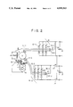
- FIG. 2 is a diagram illustrating the concept of a separately power-feeding welding generator.
- FIG. 3 is a waveform diagram of assistance in explaining the operation of the same welding generator.
- FIG. 4 is a circuit diagram of a thyristor control signal generator and an a-c voltage detector of the conventional type.
- a separately power-feeding welding generator will be outlined, referring to FIG. 2 showing the concept of the separately power-feeding welding generator.
- reference numeral 3 refers to a generator; 5 to an a-c power winding; 6 to an excitation winding; 7 to a field winding; 8-1 and 8-2 to rectifying circuits; 11-1 and 11-2 to the output wires of main generating windings; 12-1 and 12-2 to thyristors (or thyristor groups); 13 and 14 to changeover switches, for changing over two d-c outputs separately or in parallel; 34-1 and 34-2 to diodes, provided in parallel with the thyristors 12-1 and 12-2; 35-1 and 35-2 to resistor elements.
- the thyristor groups 12-1 and/or 12-2 are adapted to control outputs by giving a reference voltage level which is determined in accordance with load current to control conduction angles in accordance therewith.
- the diodes 34-1 and 34-2 conduct when a positive half-wave voltage is applied.
- the thyristor groups 12-1 and/or 12-2 are adapted to control conduction angles.
- a thyristor corresponding to the W phase for example, is taken as an example among the thyrstors corresponding to the U phase, the V phase and the W phase
- the conduction angle of the thyristor corresponding to the W phase is adapted to be controlled in accordance with the reference voltage level determined in accordance with load current, as will be described later with reference to FIGS. 1 and 3.
- the thyristor group 12-1 is controlled in accordance with that level.
- the respective welding currents thereof can also be controlled separetely.
- the voltages appearing on the positive and negative terminals shown in the figure may be temporarily interrupted because the conduction angles of the thyristor groups 12-1 and 12-2 are controlled. But such voltage interruption is prevented because voltage is fed from the diodes 34-1 and 34-2 immediately before the interruption.
- FIG. 1 shows a circuit configuration of an embodiment of this invention in which the thyristor corresponding to the W phase is controlled.
- FIG. 3 is a waveform diagram of assistance in explaining the operation.
- FIG. 1 shows a circuit configuration having only one main generating winding and one rectifying circuit for simplicity. Only a configuration for controlling the thyristor of the W phase is shown also for simplicity.
- reference numerals 3, 8-1, 11-1, 12-1, 34-1 and 35-1 correspond to like numerals shown in FIG. 2.
- 12-1W represents a thyristor corresponding to the W phase.
- Numeral 4 refers to a main generating winding; 17 through 19 to comparators; 20 through 22 to photocouplers; 23U, 23V and 23W to thyristor controllers; 24 to a transistor; 25 to an FET; 26-1 and 26-2 to voltage generators for setting reference voltage levels; 27 to a comparator; 28 to a photocoupler; and 29 to a capacitor; 31 to a first control power supply consisting of a rectifying circuit 31-1 for converting the a-c output of the generator 3, a Zener diode 31-2, a capacitor 31-3 and a resistor element 31-4; 41 to a second control power supply consisting of a constant voltage generator comprising a transistor 41-11, a Zener diode 41-12 and a resistor element 41-13, a battery 41-2, a di
- the three-phase output from the main generating winding 4 is converted into d-c current by the rectifying circuit 8-1.
- the d-c current is controlled by controlling the conduction angle of the thyristor 12-1.
- the controller 23W for the thyristor 12-1W is shown for simplicity, as noted above, but the controllers 23U and 23V also exist for controlling the voltages of the U phase and the V phase.
- the voltages of the U phase through the W phase in the output wires 11-1 are compared in the comparators 17 through 19. That is, the output of the comparator 17 is kept at a low level so long as the voltage of the U phase remains smaller than the voltage of the V phase.
- the output of the comparator 18 is kept at a low level so long as the voltage of the V phase remains smaller than the voltage of the W phase.
- the output of the comparator 19 is kept at a low level so long as the voltage of the W phase remains smaller than the voltage of the U phase.
- the photocoupler output u-w (30) shown in FIG. 3 represents the duration in which the photocoupler 22 shown in FIG. 1 produces an output as the comparator 19 is turned on.
- the transistor 24 is held in off state, charging the capacitor 29 via the FET 25.
- the waveform (31) in the capacitor 29 shown in FIG. 3 represents the terminal voltage in the capacitor 29.
- the comparator 27 remains on, as shown by the on duration 33 in FIG. 3, turning on the thyristor 12-1W via the photocoupler 28.
- the on duration of the thyristor 12-1W is controlled in accordance with the reference voltage level 32 corresponding to the load current.
- durations (T in the figure) in which all the thyristors in the thyristor group 12-1 (12-2) are not turned on may occur, if there do not exist the diode 34-1 (34-2) and the resistor element 35-1 (35-2) shown in FIG. 1 or FIG. 2.
- the diode 34-1 (34-2) is provided in parallel with the thyristor group 12-1 (12-2) and connected to the positive terminal via the resistor element 35-1 (35-2). For this reason, even when a duration T in which the thyristor is not turned on is about to occur, voltage is fed to the postive terminal via the diode 34-1 (34-2) during the duration, preventing the voltage on the positive terminal from being interrupted. Thus, there is no likelihood of arc unwantedly disappearing during welding.
- control voltage of the thyristor control circuit is supplied from the d-c power supply 15 and the d-c power supply control circuit 16.
- control power supplies are separately provided for the a-c voltage detector (the section shown by arrow A) constituting the thyristor control circuit and the thyristor control signal generator (the section shown by arrow B). That is, the control voltage for the a-c voltage detector is supplied from the first control power supply 31 by using the output voltage of the generator 3, and the control voltage for the thyristor control signal generator is supplied from the second control power supply 41.
- the a-c output of the generator 3 is converted into d-c voltage in the rectifying circuit 31-1 and supplied as the control voltage for the a-c voltage detector.
- the Zener diode 31-2 and the capacitor 31-3 are used for absorbing the surge voltage generated across the output terminals of the rectifying circuit 31-1 for some reason or other.
- the capacitors C1, C2 and C3, and the Zener diodes Z1, Z2 and Z3 perform similar functions.
- the semiconductor elements in the thyristor control signal generator can be protected from being damaged by electrically insulating the battery 41-2 from the a-c output of the generator 3 because even when a dielectric strength test is performed on the generator 3, test voltage is not applied directly to the semiconductor elements.
- the transistor 41-11 and the semiconductor elements of the thyristor control signal generator are prevented from being damaged even when the terminal voltage of the battery 41-2 happen to rise for some reason or other.
- the diode 41-3 in the second control power supply 41 is used to prevent electric current from flowing in the battery 41-2 in the opposite direction, and the capacitor 41-4 and 41-5 are provided for absorbing surge voltage.
- this invention makes it possible to separately control outputs from a plurality of main generating windings, and protect the semiconductors in the thyristor control circuit from being damaged during a dielectric strength test by having such a construction that the control power supplies for the a-c voltage detector the thyristor control circuit constituting the thyristor circuit are separately provided, and the battery power supply for feeding control voltage to the thyristor control signal generator is insulated from the a-c output of the generator.
- This invention also makes it possible to reduce the difference between the welding current and the shortcircuited current without unwantedly reducing the non-load voltage. Furthermore, the voltage across the output terminals can be prevented from being interrupted, and semiconductor elements can be protected from being damaged since the surge voltage produced by intermittent welding operation.
Abstract
A separately power-feeding welding generator having at least two main generating windings for supplying power to loads by rectifying an induced voltage and adapted to permit the power being fed from the two main generating windings to the loads to be separately controlled, in which
a thyristor is provided in a rectifying circuit for rectifying a voltage induced in at least one of the two main generating windings;
an a-c voltage detector for detecting the voltage induced in at least one of the two main generating windings and
a thyristor control signal generator for controlling the conduction angle of the thyristor on the basis of the detected signal of the a-c voltage detector and the reference level obtained by extracting the level of the current being fed to the loads are provided;
a diode which conducts when a positive half-wave is applied in parallel with the thyristor is connected in series with a resistor element;
a first control power supply for rectifying a voltage induced in at least one of the two main generating windings to supply as a control voltage to the a-c voltage detector and
a second control power supply which is electrically independent from the first control power supply and supplies a control voltage to the thyristor control signal generator are provided.
Description
1. Field of the Invention
This invention relates generally to a separately power-feeding welding generator, and more particularly to a separately power-feeding welding generator adapted to control the output of at least one of main generating windings by thyristor control to ensure separate power-feeding control.
2. Description of the Prior Art
The present applicant previously proposed in Japanese patent application No. 133930-1984 a separately power-feeding welding generator having main generating windings for a plurality of welding power supplies and adapted to control the output of at least one of the main generating windings by means of thyristor control to ensure separate power-feeding control.
FIG. 4 is a circuit diagram of the welding generator previously proposed by the present applicant. With this circuit configuration, a separately power-feeding welding generator has been realized, in which outputs from a plurality of main generating windings can be independently controlled, and the difference between a current during welding and a current in a shortcircuited state can be reduced without unwantedly reducing no-load current, and the voltage across the output terminals is prevented from being interrupted.
In FIG. 4, a circuit configuration having only one main generating winding and only one rectifying circuit is shown in the interest of simplicity. In addition, a circuit configuration for controlling a thyristor corresponding to the W phase is shown for also simplicity.
With this circuit configuration, however, the following unwanted problems are encountered due to different electrical appliance and material control laws in various countries.
(1) In a dielectric strength test (between the output terminal of the generator and the ground), semi-conductor elements might be damaged because test voltage is applied directly to the thyristor control circuit.
(2) If the voltage applied across the battery terminals becomes excessive (over 20 volts, for example) due to the failure of the regulator (not shown in FIG. 4) for charging the battery (the d-c power supply 15 in FIG. 4) for supplying control voltage to the control circuit, the d-c power supply control circuit 16 shown in FIG. 4 might be adversely affected.
Therefore, a circuit configuration suited to electrical appliance and material control laws in various countries has long been hoped for.
It is an object of this invention to provide a separately power-feeding welding generator adapted to protect semiconductor elements in the thyristor control circuit during a dielectric strength test.
It is another object of this invention to provide a control power supply which never adversely affects the thyristor control circuit even when excessive voltage is applied to the battery as a d-c power supply during charging.
It is still another object of this invention to provide a surge voltage absorbing circuit for absorbing the surge voltage generated as a result of intermittent welding operations.
FIG. 1 is a circuit diagram of a thyristor control signal generator and an a-c voltage detector in an embodiment of this invention.
FIG. 2 is a diagram illustrating the concept of a separately power-feeding welding generator.
FIG. 3 is a waveform diagram of assistance in explaining the operation of the same welding generator.
FIG. 4 is a circuit diagram of a thyristor control signal generator and an a-c voltage detector of the conventional type.
First, a separately power-feeding welding generator will be outlined, referring to FIG. 2 showing the concept of the separately power-feeding welding generator.
In FIG. 2, reference numeral 3 refers to a generator; 5 to an a-c power winding; 6 to an excitation winding; 7 to a field winding; 8-1 and 8-2 to rectifying circuits; 11-1 and 11-2 to the output wires of main generating windings; 12-1 and 12-2 to thyristors (or thyristor groups); 13 and 14 to changeover switches, for changing over two d-c outputs separately or in parallel; 34-1 and 34-2 to diodes, provided in parallel with the thyristors 12-1 and 12-2; 35-1 and 35-2 to resistor elements. Though not shown in the figure, the thyristor groups 12-1 and/or 12-2 are adapted to control outputs by giving a reference voltage level which is determined in accordance with load current to control conduction angles in accordance therewith. The diodes 34-1 and 34-2 conduct when a positive half-wave voltage is applied.
In FIG. 2, the thyristor groups 12-1 and/or 12-2 are adapted to control conduction angles. When a thyristor corresponding to the W phase, for example, is taken as an example among the thyrstors corresponding to the U phase, the V phase and the W phase, the conduction angle of the thyristor corresponding to the W phase is adapted to be controlled in accordance with the reference voltage level determined in accordance with load current, as will be described later with reference to FIGS. 1 and 3.
Consequently, as the reference voltage level (the reference voltage level set corresponding to the first main generating winding) is set at a desired level, the thyristor group 12-1 is controlled in accordance with that level. Thus, by separately controlling the thyristor groups 12-1 and 12-2, the respective welding currents thereof can also be controlled separetely.
It should be noted, however, that the voltages appearing on the positive and negative terminals shown in the figure may be temporarily interrupted because the conduction angles of the thyristor groups 12-1 and 12-2 are controlled. But such voltage interruption is prevented because voltage is fed from the diodes 34-1 and 34-2 immediately before the interruption.
FIG. 1 shows a circuit configuration of an embodiment of this invention in which the thyristor corresponding to the W phase is controlled. FIG. 3 is a waveform diagram of assistance in explaining the operation.
FIG. 1 shows a circuit configuration having only one main generating winding and one rectifying circuit for simplicity. Only a configuration for controlling the thyristor of the W phase is shown also for simplicity.
In FIG. 1, reference numerals 3, 8-1, 11-1, 12-1, 34-1 and 35-1 correspond to like numerals shown in FIG. 2. 12-1W represents a thyristor corresponding to the W phase. Numeral 4 refers to a main generating winding; 17 through 19 to comparators; 20 through 22 to photocouplers; 23U, 23V and 23W to thyristor controllers; 24 to a transistor; 25 to an FET; 26-1 and 26-2 to voltage generators for setting reference voltage levels; 27 to a comparator; 28 to a photocoupler; and 29 to a capacitor; 31 to a first control power supply consisting of a rectifying circuit 31-1 for converting the a-c output of the generator 3, a Zener diode 31-2, a capacitor 31-3 and a resistor element 31-4; 41 to a second control power supply consisting of a constant voltage generator comprising a transistor 41-11, a Zener diode 41-12 and a resistor element 41-13, a battery 41-2, a diode 41-3, capacitors 41-4 and 41-5.
The three-phase output from the main generating winding 4 is converted into d-c current by the rectifying circuit 8-1. The d-c current is controlled by controlling the conduction angle of the thyristor 12-1. In the circuit configuration shown in FIG. 1, the controller 23W for the thyristor 12-1W is shown for simplicity, as noted above, but the controllers 23U and 23V also exist for controlling the voltages of the U phase and the V phase.
The voltages of the U phase through the W phase in the output wires 11-1 are compared in the comparators 17 through 19. That is, the output of the comparator 17 is kept at a low level so long as the voltage of the U phase remains smaller than the voltage of the V phase. The output of the comparator 18 is kept at a low level so long as the voltage of the V phase remains smaller than the voltage of the W phase. The output of the comparator 19 is kept at a low level so long as the voltage of the W phase remains smaller than the voltage of the U phase. The photocoupler output u-w (30) shown in FIG. 3 represents the duration in which the photocoupler 22 shown in FIG. 1 produces an output as the comparator 19 is turned on.
During the interval the photocoupler is on, the transistor 24 is held in off state, charging the capacitor 29 via the FET 25. The waveform (31) in the capacitor 29 shown in FIG. 3 represents the terminal voltage in the capacitor 29. If the reference voltage level set by the voltage generator 26-2 is a voltage level 32, as shown in FIG. 3, then the comparator 27 remains on, as shown by the on duration 33 in FIG. 3, turning on the thyristor 12-1W via the photocoupler 28. The on duration of the thyristor 12-1W is controlled in accordance with the reference voltage level 32 corresponding to the load current. Although description has been omitted, the same applies to the voltages of the U and V phases. The voltage of the voltage generator 26-2 is used in common for controlling each of the U, V and W phases.
As shown by the on duration 33 in FIG. 3, there is a likelihood that durations (T in the figure) in which all the thyristors in the thyristor group 12-1 (12-2) are not turned on may occur, if there do not exist the diode 34-1 (34-2) and the resistor element 35-1 (35-2) shown in FIG. 1 or FIG. 2.
The diode 34-1 (34-2) is provided in parallel with the thyristor group 12-1 (12-2) and connected to the positive terminal via the resistor element 35-1 (35-2). For this reason, even when a duration T in which the thyristor is not turned on is about to occur, voltage is fed to the postive terminal via the diode 34-1 (34-2) during the duration, preventing the voltage on the positive terminal from being interrupted. Thus, there is no likelihood of arc unwantedly disappearing during welding.
In the prior art shown in FIG. 4, the control voltage of the thyristor control circuit is supplied from the d-c power supply 15 and the d-c power supply control circuit 16. In this invention, on the other hand, control power supplies are separately provided for the a-c voltage detector (the section shown by arrow A) constituting the thyristor control circuit and the thyristor control signal generator (the section shown by arrow B). That is, the control voltage for the a-c voltage detector is supplied from the first control power supply 31 by using the output voltage of the generator 3, and the control voltage for the thyristor control signal generator is supplied from the second control power supply 41.
More specifically, in the construction that the control voltage for the a-c voltage detector is supplied from the first control power supply 31, the a-c output of the generator 3 is converted into d-c voltage in the rectifying circuit 31-1 and supplied as the control voltage for the a-c voltage detector. The Zener diode 31-2 and the capacitor 31-3 are used for absorbing the surge voltage generated across the output terminals of the rectifying circuit 31-1 for some reason or other. The capacitors C1, C2 and C3, and the Zener diodes Z1, Z2 and Z3 perform similar functions.
In the construction where the control voltage for the thyristor control signal generator is provided by supplying the terminal voltage of the battery 41-2 from the second control power supply 41 via the constant voltage generating circuit 41-1, the semiconductor elements in the thyristor control signal generator can be protected from being damaged by electrically insulating the battery 41-2 from the a-c output of the generator 3 because even when a dielectric strength test is performed on the generator 3, test voltage is not applied directly to the semiconductor elements. Since consideration is given so that a transistor having a large withstanding voltage and allowable loss as the transistor 41-11 as a constituent of the constant voltage generating circuit 41-1, the transistor 41-11 and the semiconductor elements of the thyristor control signal generator are prevented from being damaged even when the terminal voltage of the battery 41-2 happen to rise for some reason or other. The diode 41-3 in the second control power supply 41 is used to prevent electric current from flowing in the battery 41-2 in the opposite direction, and the capacitor 41-4 and 41-5 are provided for absorbing surge voltage.
As described above, this invention makes it possible to separately control outputs from a plurality of main generating windings, and protect the semiconductors in the thyristor control circuit from being damaged during a dielectric strength test by having such a construction that the control power supplies for the a-c voltage detector the thyristor control circuit constituting the thyristor circuit are separately provided, and the battery power supply for feeding control voltage to the thyristor control signal generator is insulated from the a-c output of the generator. This invention also makes it possible to reduce the difference between the welding current and the shortcircuited current without unwantedly reducing the non-load voltage. Furthermore, the voltage across the output terminals can be prevented from being interrupted, and semiconductor elements can be protected from being damaged since the surge voltage produced by intermittent welding operation.
Claims (3)
1. A separately power-feeding welding generator having at least two main generating windings for supplying power to loads by rectifying an induced voltage and adapted to permit said power being supplied from said two main generating windings to said loads to be separately controlled, characterized in that a thyristor is provided in a rectifying circuit for rectifying a voltage induced in at least one of said two main generating windings,
an a-c voltage detector for detecting a voltage induced in at least one of said two main generating windings and a thyristor control signal generator having such a construction that the conduction angle of said thyristor is controlled in accordance with the signal detected by said a-c voltage detector and a reference level obtained by extracting the level of electric current supplied to said loads are provided, and
a first control power supply for rectifying the voltage induced by at least one of said two main generating windings to supply as a control voltage to said a-c voltage detector and
a second control power supply which is electrically independent from said first control power supply and supplies a control voltage to said thyristor control signal generator are provided.
2. A separately power-feeding welding generator as set forth in claim 1 wherein said second control power supply comprises at least a battery and a constant voltage generating circuit, supplies the terminal voltage of said battery as a control voltage for said thyristor control signal generator via said constant voltage generating circuit, and protects thyristor control circuits.
3. A separately power-feeding welding generator as set forth in claim 1 wherein surge voltage absorbers are provided in said second control power supply and said a-c voltage detector.
Applications Claiming Priority (2)
| Application Number | Priority Date | Filing Date | Title |
|---|---|---|---|
| JP1-33930 | 1989-02-14 | ||
| JP1033930A JP2695458B2 (en) | 1989-02-14 | 1989-02-14 | Welding generator capable of individual power supply |
Publications (1)
| Publication Number | Publication Date |
|---|---|
| US4999563A true US4999563A (en) | 1991-03-12 |
Family
ID=12400234
Family Applications (1)
| Application Number | Title | Priority Date | Filing Date |
|---|---|---|---|
| US07/479,763 Expired - Lifetime US4999563A (en) | 1989-02-14 | 1990-02-13 | Separately power-feeding welding generator |
Country Status (2)
| Country | Link |
|---|---|
| US (1) | US4999563A (en) |
| JP (1) | JP2695458B2 (en) |
Cited By (19)
| Publication number | Priority date | Publication date | Assignee | Title |
|---|---|---|---|---|
| US5093611A (en) * | 1989-07-20 | 1992-03-03 | Honda Giken Kogyo Kabushiki Kaisha | Output circuit for portable generators |
| US5250786A (en) * | 1990-09-27 | 1993-10-05 | Sawafuji Electric Co., Ltd. | D-C arc welding apparatus |
| US5323102A (en) * | 1990-06-28 | 1994-06-21 | Nippondenso Co., Ltd. | Power source unit for an automotive vehicle |
| US5408067A (en) * | 1993-12-06 | 1995-04-18 | The Lincoln Electric Company | Method and apparatus for providing welding current from a brushless alternator |
| US5506492A (en) * | 1993-11-24 | 1996-04-09 | Harris; Ronald R. | High output alternator and regulator |
| WO1999061193A1 (en) * | 1998-05-27 | 1999-12-02 | Energomat Ltd. | Dual alternator with active control |
| US6049198A (en) * | 1995-05-26 | 2000-04-11 | Robert Bosch Gmbh | Power supply device with two output voltages |
| EP1109310A2 (en) * | 1999-12-16 | 2001-06-20 | C.E. NIEHOFF & COMPANY | Alternator with regulation of multiple voltage outputs |
| US6310320B1 (en) * | 1999-01-07 | 2001-10-30 | Illinois Tool Works Inc. | Dual operator phase control engine driven welder |
| US6479794B1 (en) * | 2000-11-03 | 2002-11-12 | Illinois Tool Works Inc. | Engine driven welding power supply with dig circuit |
| US6621050B2 (en) | 2000-10-27 | 2003-09-16 | Basil L. Plantz | Portable welder |
| US20060076935A1 (en) * | 2004-10-07 | 2006-04-13 | Wiseman Steven L | Ion engine power supply |
| US20070080669A1 (en) * | 2005-10-06 | 2007-04-12 | Deere & Company, A Delaware Corporation | Dual voltage electrical system |
| CN100361772C (en) * | 2000-11-13 | 2008-01-16 | 伊利诺斯器械工程公司 | Mechanical welding power source with starting circuit |
| US20100164235A1 (en) * | 2003-10-06 | 2010-07-01 | Powersys, Llc | Power Generation Systems and Methods of Generating Power |
| EP2519374A1 (en) * | 2009-12-29 | 2012-11-07 | Lincoln Global, Inc. | A multi-output engine welder supplying full electrical power capacity to a single welding output and method |
| CN103128426A (en) * | 2013-02-26 | 2013-06-05 | 广州友田机电设备有限公司 | Multifunctional welding power source with parallel output function |
| CN103182586A (en) * | 2013-03-27 | 2013-07-03 | 昆明理工大学 | Variable control system of output characteristics of permanent-magnet passive medium-frequency electric welding machine |
| CN103831505A (en) * | 2013-11-29 | 2014-06-04 | 昆明理工大学 | Control device and method for controllable rectification of medium-frequency arc welding power supply |
Citations (5)
| Publication number | Priority date | Publication date | Assignee | Title |
|---|---|---|---|---|
| US3809995A (en) * | 1970-11-19 | 1974-05-07 | Eltra Corp | Multiple output alternator |
| US4009431A (en) * | 1975-09-08 | 1977-02-22 | General Motors Corporation | Series parallel transition for power supply |
| US4314195A (en) * | 1979-11-01 | 1982-02-02 | Hobart Brothers Company | Solid state control for motor-generator welder |
| US4539486A (en) * | 1983-02-08 | 1985-09-03 | Denyo Kabushiki Kaisha | Single-core inductor generator for welding producing multiple, mutually-independent outputs |
| US4904841A (en) * | 1988-08-15 | 1990-02-27 | English Dale L | Welder system having controllable dual winding alternator |
-
1989
- 1989-02-14 JP JP1033930A patent/JP2695458B2/en not_active Expired - Fee Related
-
1990
- 1990-02-13 US US07/479,763 patent/US4999563A/en not_active Expired - Lifetime
Patent Citations (5)
| Publication number | Priority date | Publication date | Assignee | Title |
|---|---|---|---|---|
| US3809995A (en) * | 1970-11-19 | 1974-05-07 | Eltra Corp | Multiple output alternator |
| US4009431A (en) * | 1975-09-08 | 1977-02-22 | General Motors Corporation | Series parallel transition for power supply |
| US4314195A (en) * | 1979-11-01 | 1982-02-02 | Hobart Brothers Company | Solid state control for motor-generator welder |
| US4539486A (en) * | 1983-02-08 | 1985-09-03 | Denyo Kabushiki Kaisha | Single-core inductor generator for welding producing multiple, mutually-independent outputs |
| US4904841A (en) * | 1988-08-15 | 1990-02-27 | English Dale L | Welder system having controllable dual winding alternator |
Cited By (33)
| Publication number | Priority date | Publication date | Assignee | Title |
|---|---|---|---|---|
| US5093611A (en) * | 1989-07-20 | 1992-03-03 | Honda Giken Kogyo Kabushiki Kaisha | Output circuit for portable generators |
| US5323102A (en) * | 1990-06-28 | 1994-06-21 | Nippondenso Co., Ltd. | Power source unit for an automotive vehicle |
| US5250786A (en) * | 1990-09-27 | 1993-10-05 | Sawafuji Electric Co., Ltd. | D-C arc welding apparatus |
| US5506492A (en) * | 1993-11-24 | 1996-04-09 | Harris; Ronald R. | High output alternator and regulator |
| US5408067A (en) * | 1993-12-06 | 1995-04-18 | The Lincoln Electric Company | Method and apparatus for providing welding current from a brushless alternator |
| US6049198A (en) * | 1995-05-26 | 2000-04-11 | Robert Bosch Gmbh | Power supply device with two output voltages |
| WO1999061193A1 (en) * | 1998-05-27 | 1999-12-02 | Energomat Ltd. | Dual alternator with active control |
| US6310320B1 (en) * | 1999-01-07 | 2001-10-30 | Illinois Tool Works Inc. | Dual operator phase control engine driven welder |
| EP1109310A3 (en) * | 1999-12-16 | 2003-10-29 | C.E. NIEHOFF & COMPANY | Alternator with regulation of multiple voltage outputs |
| EP1109310A2 (en) * | 1999-12-16 | 2001-06-20 | C.E. NIEHOFF & COMPANY | Alternator with regulation of multiple voltage outputs |
| US6275012B1 (en) * | 1999-12-16 | 2001-08-14 | C.E. Niehoff & Co. | Alternator with regulation of multiple voltage outputs |
| US6373230B2 (en) | 1999-12-16 | 2002-04-16 | C. E. Niehoff & Co. | Alternator with regulation of multiple voltage outputs |
| US6621050B2 (en) | 2000-10-27 | 2003-09-16 | Basil L. Plantz | Portable welder |
| US6479794B1 (en) * | 2000-11-03 | 2002-11-12 | Illinois Tool Works Inc. | Engine driven welding power supply with dig circuit |
| CN100361772C (en) * | 2000-11-13 | 2008-01-16 | 伊利诺斯器械工程公司 | Mechanical welding power source with starting circuit |
| US8492913B2 (en) | 2003-10-06 | 2013-07-23 | Powersys, Llc | Power generation systems |
| US9502943B2 (en) | 2003-10-06 | 2016-11-22 | Powersys, Llc | Power generation systems and methods of generating power |
| US20100164235A1 (en) * | 2003-10-06 | 2010-07-01 | Powersys, Llc | Power Generation Systems and Methods of Generating Power |
| US7969030B2 (en) * | 2003-10-06 | 2011-06-28 | Powersys, Llc | Power generation systems and methods of generating power |
| US8829698B2 (en) | 2003-10-06 | 2014-09-09 | Powersys, Llc | Power generation systems |
| US20060076935A1 (en) * | 2004-10-07 | 2006-04-13 | Wiseman Steven L | Ion engine power supply |
| US7365518B2 (en) * | 2004-10-07 | 2008-04-29 | L-3 Communications Electron Technologies, Inc. | Ion engine power supply |
| US20080151584A1 (en) * | 2004-10-07 | 2008-06-26 | L-3 Communications Electron Technologies, Inc. | Ion engine power supply |
| US7477042B2 (en) * | 2004-10-07 | 2009-01-13 | L-3 Communications Electron Technologies, Inc. | Ion engine power supply |
| US7224146B2 (en) * | 2005-10-06 | 2007-05-29 | Deere & Company | Dual voltage electrical system |
| US20070080669A1 (en) * | 2005-10-06 | 2007-04-12 | Deere & Company, A Delaware Corporation | Dual voltage electrical system |
| EP2519374A1 (en) * | 2009-12-29 | 2012-11-07 | Lincoln Global, Inc. | A multi-output engine welder supplying full electrical power capacity to a single welding output and method |
| CN103128426A (en) * | 2013-02-26 | 2013-06-05 | 广州友田机电设备有限公司 | Multifunctional welding power source with parallel output function |
| CN103128426B (en) * | 2013-02-26 | 2015-05-13 | 广州友田机电设备有限公司 | Multifunctional welding power source with parallel output function |
| CN103182586A (en) * | 2013-03-27 | 2013-07-03 | 昆明理工大学 | Variable control system of output characteristics of permanent-magnet passive medium-frequency electric welding machine |
| CN103182586B (en) * | 2013-03-27 | 2015-03-11 | 昆明理工大学 | Variable control system of output characteristics of permanent-magnet passive medium-frequency electric welding machine |
| CN103831505A (en) * | 2013-11-29 | 2014-06-04 | 昆明理工大学 | Control device and method for controllable rectification of medium-frequency arc welding power supply |
| CN103831505B (en) * | 2013-11-29 | 2015-11-18 | 昆明理工大学 | A kind of control device of intermediate frequency Arc Welding Power controlled rectification and method |
Also Published As
| Publication number | Publication date |
|---|---|
| JP2695458B2 (en) | 1997-12-24 |
| JPH02211981A (en) | 1990-08-23 |
Similar Documents
| Publication | Publication Date | Title |
|---|---|---|
| US4999563A (en) | Separately power-feeding welding generator | |
| KR950035037A (en) | Control circuit for inductive load | |
| US4546423A (en) | Multiple inverters with overcurrent and shoot-through protection | |
| US4340849A (en) | Ripple-compensated voltage regulator, particularly for automotive use | |
| US6437998B1 (en) | Rectifying circuit and control method therefor | |
| US5130917A (en) | Power inverter snubber circuit | |
| US6049198A (en) | Power supply device with two output voltages | |
| US5606492A (en) | Intermittent on/off regulator type DC power supply | |
| US3546550A (en) | Control circuit for braking speed control of induction motor | |
| US3299342A (en) | Semiconductor voltage regulator | |
| JP2004208345A (en) | Three-phase unbalanced voltage restraining apparatus | |
| US7276882B2 (en) | Regulator control circuit and method | |
| EP0318250B1 (en) | Controlling a control turn-off semiconductor device | |
| AU665152B2 (en) | Electric power converter/inverter and power control apparatus using the same | |
| EP0223362B1 (en) | Arrangement for switching rectified alternating current | |
| US20230308038A1 (en) | Electric motor system | |
| JP3268725B2 (en) | DC voltage detector | |
| US6906480B2 (en) | Regulator control circuit and method | |
| KR100275035B1 (en) | Control circuit of share with current in the 12-pulse rectifier | |
| SU1105971A1 (en) | Device for providing current protection of a.c.electric installation against overload | |
| KR0151785B1 (en) | Voltage controller of permanent magnet type generator | |
| SU1358033A1 (en) | Arrangement for protecting three-phase induction motor against emergency duty | |
| EP0767530B1 (en) | Regulator for permanent magnet generator and permanent magnet generator | |
| SU1077729A1 (en) | Apparatus for supplying welding arc with a.c. | |
| SU1072178A1 (en) | Device for distributing activity load between two synchronous generators operating in parallel |
Legal Events
| Date | Code | Title | Description |
|---|---|---|---|
| AS | Assignment |
Owner name: SAWAFUJI ELECTRIC CO., LTD., JAPAN Free format text: ASSIGNMENT OF ASSIGNORS INTEREST.;ASSIGNOR:SUZUKI, TOSHIMICHI;REEL/FRAME:005242/0504 Effective date: 19900112 |
|
| STCF | Information on status: patent grant |
Free format text: PATENTED CASE |
|
| FEPP | Fee payment procedure |
Free format text: PAYOR NUMBER ASSIGNED (ORIGINAL EVENT CODE: ASPN); ENTITY STATUS OF PATENT OWNER: LARGE ENTITY |
|
| FPAY | Fee payment |
Year of fee payment: 4 |
|
| FPAY | Fee payment |
Year of fee payment: 8 |
|
| FPAY | Fee payment |
Year of fee payment: 12 |