US5011626A - Barrier materials for laser drilling - Google Patents
Barrier materials for laser drilling Download PDFInfo
- Publication number
- US5011626A US5011626A US07/206,123 US20612388A US5011626A US 5011626 A US5011626 A US 5011626A US 20612388 A US20612388 A US 20612388A US 5011626 A US5011626 A US 5011626A
- Authority
- US
- United States
- Prior art keywords
- laser
- barrier material
- light
- barrier
- laser beam
- Prior art date
- Legal status (The legal status is an assumption and is not a legal conclusion. Google has not performed a legal analysis and makes no representation as to the accuracy of the status listed.)
- Expired - Fee Related
Links
Images
Classifications
-
- B—PERFORMING OPERATIONS; TRANSPORTING
- B23—MACHINE TOOLS; METAL-WORKING NOT OTHERWISE PROVIDED FOR
- B23K—SOLDERING OR UNSOLDERING; WELDING; CLADDING OR PLATING BY SOLDERING OR WELDING; CUTTING BY APPLYING HEAT LOCALLY, e.g. FLAME CUTTING; WORKING BY LASER BEAM
- B23K26/00—Working by laser beam, e.g. welding, cutting or boring
- B23K26/18—Working by laser beam, e.g. welding, cutting or boring using absorbing layers on the workpiece, e.g. for marking or protecting purposes
-
- B—PERFORMING OPERATIONS; TRANSPORTING
- B23—MACHINE TOOLS; METAL-WORKING NOT OTHERWISE PROVIDED FOR
- B23K—SOLDERING OR UNSOLDERING; WELDING; CLADDING OR PLATING BY SOLDERING OR WELDING; CUTTING BY APPLYING HEAT LOCALLY, e.g. FLAME CUTTING; WORKING BY LASER BEAM
- B23K26/00—Working by laser beam, e.g. welding, cutting or boring
- B23K26/009—Working by laser beam, e.g. welding, cutting or boring using a non-absorbing, e.g. transparent, reflective or refractive, layer on the workpiece
-
- B—PERFORMING OPERATIONS; TRANSPORTING
- B23—MACHINE TOOLS; METAL-WORKING NOT OTHERWISE PROVIDED FOR
- B23K—SOLDERING OR UNSOLDERING; WELDING; CLADDING OR PLATING BY SOLDERING OR WELDING; CUTTING BY APPLYING HEAT LOCALLY, e.g. FLAME CUTTING; WORKING BY LASER BEAM
- B23K26/00—Working by laser beam, e.g. welding, cutting or boring
- B23K26/02—Positioning or observing the workpiece, e.g. with respect to the point of impact; Aligning, aiming or focusing the laser beam
- B23K26/03—Observing, e.g. monitoring, the workpiece
- B23K26/032—Observing, e.g. monitoring, the workpiece using optical means
-
- B—PERFORMING OPERATIONS; TRANSPORTING
- B23—MACHINE TOOLS; METAL-WORKING NOT OTHERWISE PROVIDED FOR
- B23K—SOLDERING OR UNSOLDERING; WELDING; CLADDING OR PLATING BY SOLDERING OR WELDING; CUTTING BY APPLYING HEAT LOCALLY, e.g. FLAME CUTTING; WORKING BY LASER BEAM
- B23K26/00—Working by laser beam, e.g. welding, cutting or boring
- B23K26/36—Removing material
- B23K26/38—Removing material by boring or cutting
- B23K26/382—Removing material by boring or cutting by boring
- B23K26/389—Removing material by boring or cutting by boring of fluid openings, e.g. nozzles, jets
-
- B—PERFORMING OPERATIONS; TRANSPORTING
- B23—MACHINE TOOLS; METAL-WORKING NOT OTHERWISE PROVIDED FOR
- B23K—SOLDERING OR UNSOLDERING; WELDING; CLADDING OR PLATING BY SOLDERING OR WELDING; CUTTING BY APPLYING HEAT LOCALLY, e.g. FLAME CUTTING; WORKING BY LASER BEAM
- B23K26/00—Working by laser beam, e.g. welding, cutting or boring
- B23K26/36—Removing material
- B23K26/40—Removing material taking account of the properties of the material involved
-
- B—PERFORMING OPERATIONS; TRANSPORTING
- B23—MACHINE TOOLS; METAL-WORKING NOT OTHERWISE PROVIDED FOR
- B23K—SOLDERING OR UNSOLDERING; WELDING; CLADDING OR PLATING BY SOLDERING OR WELDING; CUTTING BY APPLYING HEAT LOCALLY, e.g. FLAME CUTTING; WORKING BY LASER BEAM
- B23K2103/00—Materials to be soldered, welded or cut
- B23K2103/50—Inorganic material, e.g. metals, not provided for in B23K2103/02 – B23K2103/26
Definitions
- This invention relates to laser drilling of components, and in particular, although not exclusively, to drilling holes in gas turbine components such as turbine blades.
- An object of the present invention is to provide a method of laser drilling which uses a barrier material that is easy to fill the cavities, is self supporting in the cavity, is easy to remove, and is effective in preventing the laser beam damaging the surfaces of the cavity.
- a further object of the present invention is to provide a means for monitoring the size of the hole being drilled by the laser and for controlling the laser beam.
- FIG. 1 illustrates schematically apparatus incorporating the present invention
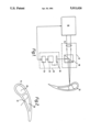
- FIG. 2 illustrates a turbine blade suitable for being drilled using the apparatus of FIG. 1.
- the apparatus comprises a pulsed Nd-YAG laser 10 (typically of the type manufactured and sold in the USA by RAYCON).
- the laser produces a beam of approximately 0.010 to 0.030 ins diameter with an average energy of 400 watts.
- An optical system 12 is provided which includes a lens 14 for focusing the laser beam on to the surface of the component to be drilled.
- the component 16 may be a turbine blade 16 as shown in FIG. 2.
- the optical system 12 includes a beam splitter 18 or half silvered mirror, which directs light received from the component to a monitoring and detection system 20.
- the monitoring system comprises a spectrographic analyzer 22, and a laser control system 24.
- FIG. 2 there is shown schematically a cross-section through the airfoil of a turbine blade 16 which is to be drilled using the apparatus of FIG. 1.
- the turbine blade 16 comprises one or more cooling passages 28 which extend from the root portion through the airfoil portion.
- the apparatus of FIG. 1 is intended to be used for drilling the very small diameter film-cooling holes 32 which pass through the wall of the blade into the internal cavities or passages 28.
- At least inner surfaces of the passages 28 are contacted prior to drilling the holes 32 with a visco-elastic medium which is a thixotropic slurry comprising material for dispersing the laser light and material which emits light when the laser light contacts it. Ideally the whole of the passages 28 are filled with the slurry.
- the slurry can be a colloidal sol, a colloidal gel, or a mixture or suspension which is thixotropic, and will form at least a self supporting coating on the surfaces of the passages 28.
- Polyacrylamide is a water soluble high polymer used as a flocculation agent in water and waste treatment applications.
- acrylic acrylic particles for example Amberlite (Registered Trade Mark of Rohm and Haas), which is effective in dispersing the laser beam.
- Other dispersants such as polytetrafluoroethylene (PTFE), TiO 2 , phosphors, and light scattering oxides could be used.
- PTFE polytetrafluoroethylene
- TiO 2 titanium oxide
- phosphors phosphors
- light scattering oxides could be used. The effectiveness of the laser dispersant material will depend upon the following factors.
- (a) size of the dispersant particles--the preferred size is greater than the wave length of the laser light and probably in the range of 30 to 70 ⁇ m (or at least small enough not to block the hole to be drilled)
- a light emitting material is added to the slurry.
- the light emitting material may be a chromophore of the electron donor type, such as for example an auxochrome or an electron acceptor type.
- the electron donor types would fluoresce at longer wavelengths than the exciting laser light where as the electron acceptor types emit shorter wavelengths.
- Suitable auxochromes are believed to be stilbene or its derivatives. Stilbene is insoluble in water and is well suited for our needs.
- light emitting material may be suitable providing that they are relatively inert towards the alloy being drilled.
- ionic complexes may be suitable.
- phosphorescent, or luminescent materials may also be suitable.
- a suitable slurry is one that comprises a suspension of 1 to 5% polyacrylamide in water in which is added typically 25% (or more) acrylic particles which have been colored by the application of a colored fluorescent dye.
- the thixotropic slurry is injected through a nozzle so as to impart a high amount of shear and thereby lower the viscosity to enable the slurry to flow readily into the passages 28.
- the slurry is allowed to become highly viscous and self supporting in the passage 28.
- the turbine blade 16 is then positioned in the path of the laser beam and aligned to enable the desired holes to be drilled.
- the detection system 20 is set to discriminate between the spectrum of light emitted by the fluorescent material, and the light reflected or emitted by the turbine blade as it is drilled, and the laser is switched on to produce pulses of laser light.
- the monitoring and detection system 20 has a two dimensional light sensitive receiver such as a digital camera 30 so that an image can be produced of the shape and size of the hole.
- Image intensifying devices and image analyzing devices could be employed to extract information from the image in terms of hole shape and size if desired.
- the monitoring system can be programmed to respond to image of the shape and size of the hole to control the laser and switch it off when a predetermined shape and size is detected.
- the slurry also protects the inner surfaces of the passages 28 and prevents any sputtered or vaporized materials from coating the surfaces of the passages 28.
- the slurry is washed away by flowing water through the passages 28.
Abstract
Description
Claims (7)
Priority Applications (4)
| Application Number | Priority Date | Filing Date | Title |
|---|---|---|---|
| US07/206,123 US5011626A (en) | 1988-06-13 | 1988-06-13 | Barrier materials for laser drilling |
| DE89305304T DE68907527T2 (en) | 1988-06-13 | 1989-05-25 | Laser drilling of components. |
| EP89305304A EP0347053B1 (en) | 1988-06-13 | 1989-05-25 | Laser drilling of components |
| JP1150340A JPH0237984A (en) | 1988-06-13 | 1989-06-13 | Method and device for boring hole by using laser |
Applications Claiming Priority (1)
| Application Number | Priority Date | Filing Date | Title |
|---|---|---|---|
| US07/206,123 US5011626A (en) | 1988-06-13 | 1988-06-13 | Barrier materials for laser drilling |
Publications (1)
| Publication Number | Publication Date |
|---|---|
| US5011626A true US5011626A (en) | 1991-04-30 |
Family
ID=22765078
Family Applications (1)
| Application Number | Title | Priority Date | Filing Date |
|---|---|---|---|
| US07/206,123 Expired - Fee Related US5011626A (en) | 1988-06-13 | 1988-06-13 | Barrier materials for laser drilling |
Country Status (1)
| Country | Link |
|---|---|
| US (1) | US5011626A (en) |
Cited By (21)
| Publication number | Priority date | Publication date | Assignee | Title |
|---|---|---|---|---|
| US5140127A (en) * | 1989-09-20 | 1992-08-18 | Rolls-Royce Plc | Laser barrier material |
| US5222617A (en) * | 1990-10-17 | 1993-06-29 | Rolls-Royce Plc | Drilling turbine blades |
| US5767482A (en) * | 1995-07-14 | 1998-06-16 | Rolls Royce Plc | Laser barrier material and method |
| US5773790A (en) * | 1997-01-21 | 1998-06-30 | General Electric Company | Beam blocking material and method for beam drilling and inspecting cooling holes |
| US5914060A (en) * | 1998-09-29 | 1999-06-22 | United Technologies Corporation | Method of laser drilling an airfoil |
| US5928534A (en) * | 1998-09-29 | 1999-07-27 | United Technologies Corporation | Method for reducing void volumes in cavities for laser drilling |
| US6054673A (en) * | 1997-09-17 | 2000-04-25 | General Electric Company | Method and apparatus for laser drilling |
| US6172331B1 (en) | 1997-09-17 | 2001-01-09 | General Electric Company | Method and apparatus for laser drilling |
| US6201214B1 (en) * | 1998-02-19 | 2001-03-13 | M. J. Technologies, Limited | Laser drilling with optical feedback |
| US6251315B1 (en) * | 1998-11-20 | 2001-06-26 | United Technologies Corporation | Method for disposing a laser blocking material on the interior of an airfoil |
| US6329633B1 (en) * | 1998-11-20 | 2001-12-11 | United Technologies Corporation | Method and material for processing a component for laser machining |
| US6359254B1 (en) * | 1999-09-30 | 2002-03-19 | United Technologies Corporation | Method for producing shaped hole in a structure |
| US20050248060A1 (en) * | 2002-06-28 | 2005-11-10 | 3M Innovative Properties Company | Manufacture of valve stems |
| US20080092887A1 (en) * | 2004-12-07 | 2008-04-24 | Hodson Peter D | Single-Dose Inhalation Devices |
| US20080152802A1 (en) * | 2006-12-23 | 2008-06-26 | Mtu Aero Engines Gmbh | Method for cleaning, method and device for the application of a protective medium to a turbine blade, and a method for placing cooling bores in a turbine blade |
| US20080202515A1 (en) * | 2004-12-23 | 2008-08-28 | 3M Innovative Properties Company | Inhalation Device |
| US20080271733A1 (en) * | 2004-12-14 | 2008-11-06 | Gary Ka Lai Ng | Methods of Providing Medicinal Metal Components Having Through Holes |
| US20120000893A1 (en) * | 2010-06-30 | 2012-01-05 | Resonetics, LLC | Precision Laser Ablation |
| WO2012107331A1 (en) * | 2011-02-07 | 2012-08-16 | Trumpf Werkzeugmaschinen Gmbh + Co. Kg | Device and method for monitoring and in particular controlling a laser cutting process |
| WO2016008080A1 (en) * | 2014-07-14 | 2016-01-21 | 西门子公司 | System and method for machining holes on workpiece using laser pulses |
| US9815141B2 (en) | 2011-12-07 | 2017-11-14 | General Atomics | Methods and systems for use in laser machining |
Citations (6)
| Publication number | Priority date | Publication date | Assignee | Title |
|---|---|---|---|---|
| US4202697A (en) * | 1977-06-01 | 1980-05-13 | Agfa-Gevaert N.V. | Production of etch-resist colloid and material suitable therefor |
| US4282928A (en) * | 1977-07-08 | 1981-08-11 | The Dow Chemical Co. | Method for controlling permeability of subterranean formations |
| US4657345A (en) * | 1985-03-11 | 1987-04-14 | Barnes Engineering Company | Laser shield and method of making same |
| US4689307A (en) * | 1986-09-02 | 1987-08-25 | Caribbean Microparticles Corporation | Fluorescence microscopy sample mounting method and structure |
| US4766048A (en) * | 1986-02-20 | 1988-08-23 | Canon Kabushiki Kaisha | Electrophotographic photosensitive member having surface layer containing fine spherical resin powder and apparatus utilizing the same |
| US4873414A (en) * | 1988-06-13 | 1989-10-10 | Rolls Royce Inc. | Laser drilling of components |
-
1988
- 1988-06-13 US US07/206,123 patent/US5011626A/en not_active Expired - Fee Related
Patent Citations (6)
| Publication number | Priority date | Publication date | Assignee | Title |
|---|---|---|---|---|
| US4202697A (en) * | 1977-06-01 | 1980-05-13 | Agfa-Gevaert N.V. | Production of etch-resist colloid and material suitable therefor |
| US4282928A (en) * | 1977-07-08 | 1981-08-11 | The Dow Chemical Co. | Method for controlling permeability of subterranean formations |
| US4657345A (en) * | 1985-03-11 | 1987-04-14 | Barnes Engineering Company | Laser shield and method of making same |
| US4766048A (en) * | 1986-02-20 | 1988-08-23 | Canon Kabushiki Kaisha | Electrophotographic photosensitive member having surface layer containing fine spherical resin powder and apparatus utilizing the same |
| US4689307A (en) * | 1986-09-02 | 1987-08-25 | Caribbean Microparticles Corporation | Fluorescence microscopy sample mounting method and structure |
| US4873414A (en) * | 1988-06-13 | 1989-10-10 | Rolls Royce Inc. | Laser drilling of components |
Cited By (28)
| Publication number | Priority date | Publication date | Assignee | Title |
|---|---|---|---|---|
| US5140127A (en) * | 1989-09-20 | 1992-08-18 | Rolls-Royce Plc | Laser barrier material |
| US5222617A (en) * | 1990-10-17 | 1993-06-29 | Rolls-Royce Plc | Drilling turbine blades |
| US5767482A (en) * | 1995-07-14 | 1998-06-16 | Rolls Royce Plc | Laser barrier material and method |
| US5773790A (en) * | 1997-01-21 | 1998-06-30 | General Electric Company | Beam blocking material and method for beam drilling and inspecting cooling holes |
| EP0854005A2 (en) * | 1997-01-21 | 1998-07-22 | General Electric Company | Beam blocking material and method for beam drilling and inspecting cooling holes |
| EP0854005A3 (en) * | 1997-01-21 | 1998-07-29 | General Electric Company | Beam blocking material and method for beam drilling and inspecting cooling holes |
| US6172331B1 (en) | 1997-09-17 | 2001-01-09 | General Electric Company | Method and apparatus for laser drilling |
| US6054673A (en) * | 1997-09-17 | 2000-04-25 | General Electric Company | Method and apparatus for laser drilling |
| US6201214B1 (en) * | 1998-02-19 | 2001-03-13 | M. J. Technologies, Limited | Laser drilling with optical feedback |
| US5928534A (en) * | 1998-09-29 | 1999-07-27 | United Technologies Corporation | Method for reducing void volumes in cavities for laser drilling |
| US5914060A (en) * | 1998-09-29 | 1999-06-22 | United Technologies Corporation | Method of laser drilling an airfoil |
| US6251315B1 (en) * | 1998-11-20 | 2001-06-26 | United Technologies Corporation | Method for disposing a laser blocking material on the interior of an airfoil |
| US6329633B1 (en) * | 1998-11-20 | 2001-12-11 | United Technologies Corporation | Method and material for processing a component for laser machining |
| US6359254B1 (en) * | 1999-09-30 | 2002-03-19 | United Technologies Corporation | Method for producing shaped hole in a structure |
| US20050248060A1 (en) * | 2002-06-28 | 2005-11-10 | 3M Innovative Properties Company | Manufacture of valve stems |
| US20080092887A1 (en) * | 2004-12-07 | 2008-04-24 | Hodson Peter D | Single-Dose Inhalation Devices |
| US20080271733A1 (en) * | 2004-12-14 | 2008-11-06 | Gary Ka Lai Ng | Methods of Providing Medicinal Metal Components Having Through Holes |
| US20080202515A1 (en) * | 2004-12-23 | 2008-08-28 | 3M Innovative Properties Company | Inhalation Device |
| US20080152802A1 (en) * | 2006-12-23 | 2008-06-26 | Mtu Aero Engines Gmbh | Method for cleaning, method and device for the application of a protective medium to a turbine blade, and a method for placing cooling bores in a turbine blade |
| US20120000893A1 (en) * | 2010-06-30 | 2012-01-05 | Resonetics, LLC | Precision Laser Ablation |
| US8772671B2 (en) * | 2010-06-30 | 2014-07-08 | Resonetics, LLC | Precision laser ablation |
| CN103347642A (en) * | 2011-02-07 | 2013-10-09 | 通快机床两合公司 | Device and method for monitoring and in particular controlling a laser cutting process |
| WO2012107331A1 (en) * | 2011-02-07 | 2012-08-16 | Trumpf Werkzeugmaschinen Gmbh + Co. Kg | Device and method for monitoring and in particular controlling a laser cutting process |
| CN103347642B (en) * | 2011-02-07 | 2016-08-10 | 通快机床两合公司 | For monitoring and especially for the apparatus and method adjusting laser cutting process |
| US10058953B2 (en) | 2011-02-07 | 2018-08-28 | Trumpf Werkzeugmaschinen Gmbh + Co. Kg | Method for monitoring and controlling a laser cutting process |
| US10888954B2 (en) | 2011-02-07 | 2021-01-12 | Trumpf Werkzeugmaschinen Gmbh + Co. Kg | Method for monitoring and controlling a laser cutting process |
| US9815141B2 (en) | 2011-12-07 | 2017-11-14 | General Atomics | Methods and systems for use in laser machining |
| WO2016008080A1 (en) * | 2014-07-14 | 2016-01-21 | 西门子公司 | System and method for machining holes on workpiece using laser pulses |
Similar Documents
| Publication | Publication Date | Title |
|---|---|---|
| US4873414A (en) | Laser drilling of components | |
| US5011626A (en) | Barrier materials for laser drilling | |
| EP0347053A2 (en) | Laser drilling of components | |
| Noack et al. | Influence of pulse duration on mechanical effects after laser-induced breakdown in water | |
| US7316067B2 (en) | Forming a perforate membrane by laser drilling and a subsequent electro-polishing step | |
| Ben-Yakar et al. | Femtosecond laser ablation properties of borosilicate glass | |
| Ziener et al. | Specular reflectivity of plasma mirrors as a function of intensity, pulse duration, and angle of incidence | |
| Zhu et al. | Influence of laser parameters and material properties on micro drilling with femtosecond laser pulses | |
| US3440388A (en) | Method for machining with laser beam | |
| JP2004347608A (en) | Flow fluorescence method and apparatus | |
| US20070175872A1 (en) | Laser back wall protection by particulate shading | |
| KR20090079194A (en) | Composition for forming a laser-markable coating and a laser-markable material containing organic absorption enhancement additives | |
| Pettit et al. | Fluence‐dependent transmission of polyimide at 248 nm under laser ablation conditions | |
| JPH08227919A (en) | Marking method for integrated circuit using laser and equipment therefor | |
| Caverhill et al. | An investigation into the use of a laser for the removal of modern ink marks from paper | |
| Hamilton et al. | Hole drilling studies with a variable pulse length CO2 laser | |
| Salminen et al. | The effect of laser and welding parameters on keyhole and melt pool behavior during fiber laser welding | |
| Jundt et al. | Microscopic material interactions by laser engraving | |
| Ventzek et al. | Copper vapor laser machining of polyimide and polymethylmethacrylate in atmospheric pressure air | |
| Arnot et al. | Plasma plume effects in pulsed carbon dioxide laser spot welding | |
| Russ et al. | Shorter than short: How does the pulse duration influence the process efficiency of conductive materials? | |
| Cottet et al. | Two‐dimensional study of shock breakout at the rear face of laser irradiated metallic targets | |
| Salminen et al. | The effect of welding parameters on keyhole and melt pool behavior during laser welding with high power fiber laser | |
| CN107164724A (en) | The quantity of coating machine and target particulate determines method | |
| Abrosimov et al. | Use of a laser medium in photography of a surface shielded by a plasma layer |
Legal Events
| Date | Code | Title | Description |
|---|---|---|---|
| AS | Assignment |
Owner name: ROLLS-ROYCE, INC., 475 STEAMBOAT ROAD, BOX 2525, G Free format text: ASSIGNMENT OF ASSIGNORS INTEREST.;ASSIGNORS:MA, KONG;PINDER, JOHN T.;REEL/FRAME:004894/0369;SIGNING DATES FROM Owner name: ROLLS-ROYCE, INC., CONNECTICUT Free format text: ASSIGNMENT OF ASSIGNORS INTEREST;ASSIGNORS:MA, KONG;PINDER, JOHN T.;REEL/FRAME:004894/0369 Effective date: 19851201 |
|
| FEPP | Fee payment procedure |
Free format text: PAYOR NUMBER ASSIGNED (ORIGINAL EVENT CODE: ASPN); ENTITY STATUS OF PATENT OWNER: LARGE ENTITY |
|
| FPAY | Fee payment |
Year of fee payment: 4 |
|
| REMI | Maintenance fee reminder mailed | ||
| LAPS | Lapse for failure to pay maintenance fees | ||
| FP | Lapsed due to failure to pay maintenance fee |
Effective date: 19990430 |
|
| STCH | Information on status: patent discontinuation |
Free format text: PATENT EXPIRED DUE TO NONPAYMENT OF MAINTENANCE FEES UNDER 37 CFR 1.362 |