US5012822A - Method for controlling urinary incontinence - Google Patents
Method for controlling urinary incontinence Download PDFInfo
- Publication number
- US5012822A US5012822A US07/580,198 US58019890A US5012822A US 5012822 A US5012822 A US 5012822A US 58019890 A US58019890 A US 58019890A US 5012822 A US5012822 A US 5012822A
- Authority
- US
- United States
- Prior art keywords
- urethra
- balloon
- patient
- bladder
- compression
- Prior art date
- Legal status (The legal status is an assumption and is not a legal conclusion. Google has not performed a legal analysis and makes no representation as to the accuracy of the status listed.)
- Expired - Fee Related
Links
Images


Classifications
-
- A—HUMAN NECESSITIES
- A61—MEDICAL OR VETERINARY SCIENCE; HYGIENE
- A61F—FILTERS IMPLANTABLE INTO BLOOD VESSELS; PROSTHESES; DEVICES PROVIDING PATENCY TO, OR PREVENTING COLLAPSING OF, TUBULAR STRUCTURES OF THE BODY, e.g. STENTS; ORTHOPAEDIC, NURSING OR CONTRACEPTIVE DEVICES; FOMENTATION; TREATMENT OR PROTECTION OF EYES OR EARS; BANDAGES, DRESSINGS OR ABSORBENT PADS; FIRST-AID KITS
- A61F2/00—Filters implantable into blood vessels; Prostheses, i.e. artificial substitutes or replacements for parts of the body; Appliances for connecting them with the body; Devices providing patency to, or preventing collapsing of, tubular structures of the body, e.g. stents
- A61F2/0004—Closure means for urethra or rectum, i.e. anti-incontinence devices or support slings against pelvic prolapse
- A61F2/0031—Closure means for urethra or rectum, i.e. anti-incontinence devices or support slings against pelvic prolapse for constricting the lumen; Support slings for the urethra
- A61F2/0036—Closure means for urethra or rectum, i.e. anti-incontinence devices or support slings against pelvic prolapse for constricting the lumen; Support slings for the urethra implantable
- A61F2/004—Closure means for urethra or rectum, i.e. anti-incontinence devices or support slings against pelvic prolapse for constricting the lumen; Support slings for the urethra implantable inflatable
-
- A—HUMAN NECESSITIES
- A61—MEDICAL OR VETERINARY SCIENCE; HYGIENE
- A61F—FILTERS IMPLANTABLE INTO BLOOD VESSELS; PROSTHESES; DEVICES PROVIDING PATENCY TO, OR PREVENTING COLLAPSING OF, TUBULAR STRUCTURES OF THE BODY, e.g. STENTS; ORTHOPAEDIC, NURSING OR CONTRACEPTIVE DEVICES; FOMENTATION; TREATMENT OR PROTECTION OF EYES OR EARS; BANDAGES, DRESSINGS OR ABSORBENT PADS; FIRST-AID KITS
- A61F2/00—Filters implantable into blood vessels; Prostheses, i.e. artificial substitutes or replacements for parts of the body; Appliances for connecting them with the body; Devices providing patency to, or preventing collapsing of, tubular structures of the body, e.g. stents
- A61F2/0004—Closure means for urethra or rectum, i.e. anti-incontinence devices or support slings against pelvic prolapse
- A61F2/0031—Closure means for urethra or rectum, i.e. anti-incontinence devices or support slings against pelvic prolapse for constricting the lumen; Support slings for the urethra
- A61F2/0036—Closure means for urethra or rectum, i.e. anti-incontinence devices or support slings against pelvic prolapse for constricting the lumen; Support slings for the urethra implantable
Definitions
- the present invention pertains generally to the treatment of urinary incontinence and more particularly to an incontinent bladder control method and apparatus incorporating a prosthesis for selectively restricting urine flow in a urethra.
- Both males and females have an external sphincter formed about the urethra which, when functioning normally, constricts the urethra and prevents flow of urine from the bladder except when the bladder is voided during normal urination.
- Urinary incontinence may result from several causes. For example, in females stretching or lengthening of the pelvic attachments to the bladder and urethra (termed cystocele or urethrocele) may occur, such as following a normal vaginal parturition, thereby allowing the bladder to descend from a normal position (FIG. 1) into a lower position (FIG. 2) thus functionally shortening the urethra.
- This form of incontinence may be surgically corrected by re-securing the bladder and urethra into a normal or near-normal position in the pelvis (FIG. 3), thereby regaining normal or additional urethral length.
- the essential elements of the sphincter are intact.
- a further object of the invention is to provide a prosthesis which is simply constructed and which may be easily used by a patient to selectively restrict or permit urine flow in the urethra.
- Another object is to provide such a urinary incontinence treatment method and apparatus capable of restricting urine flow without compressing the urethra to the extent that tissue loss or necrosis occurs.
- Yet another object of the invention as aforesaid is to enable treatment of incontinence in both males and females in the same way and with similar effectiveness.
- the apparatus of the invention comprises a reservoir containing fluid and an inflatable compression means positionable between the bone of a human pelvis and the urinary bladder and in fluid communication with the reservoir.
- a releasable one-way valve means is included between the reservoir and compression means for controlling and maintaining inflation of the compression means.
- the compression means is designed to fit between the posterior symphysis of the patient's pubis and anterior side of the patient's urethra. So positioned, inflation of the compression means compresses the urethra along one side and over an extended area to occlude the urethral lumen.
- Means for directing inflation of the compression means can be provided to direct expansion of the compression means preferentially in an inferior-posterior direction, i.e., parallel to the posterior symphysis pubis, to impinge upon the anterior aspect of the urethra.
- the method of the instant invention comprises the steps of (a) elevating the patient's bladder, (b) elongating the urethra and (c) compressing a lengthwise extent of the urethra. This is preferably done by surgically implanting the inflatable compression means at the neck of the elevated bladder between the pubis and ventral side of the urethra and releasably inflating the compression means. Inflation of the compression means can be directionally channelled for urging the same against the urethra substantially along its length.
- Placement and operational effectiveness of the compression means are aided by elevating the bladder. This functionally lengthens the urethra and reduces lumen size so that it can be occluded more easily by inflating the compression means. Inflation of the compression means on only one side of the urethra and over an extended area of its length minimizes risk of necrosis of urethral tissue. Additionally, because compression of the urethra is on one side and against lower abdominal contents, control will be at least partially responsive to intraabdominal pressure variations, e.g., due to bladder filling, coughing, so as to help maintain continence.
- FIG. 1 is a simplified diagram showing a lateral sectional view of a normal bladder and pubis of a human female in standing position.
- FIG. 2 is a view similar to FIG. 1 showing a cystocele and urethrocele condition.
- FIG. 3 illustrates a conventional surgical correction of the condition shown in FIG. 2.
- FIG. 4 is a view similar to FIG. 1 showing a simplified diagram illustrating implementation of the present invention to correct urinary incontinence in either male or female.
- FIG. 5 is a more detailed lateral view of the device shown implanted in FIG. 4.
- FIG. 5A is a frontal elevation view taken along line 5A--5A in FIG. 5.
- FIG. 5B is a longitudinal section view taken along line 5B--5B in FIG. 5.
- FIG. 5C is a cross-sectional view taken along line 5C--5C in FIG. 5B.
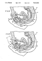
- FIG. 6 is a sectional view taken along lines 6--6 in FIG. 5A showing interior details and operation of the first embodiment with the reservoir being inflated and compression balloon deflated in solid-lines and the reservoir deflated and compression balloon inflated in dashed lines.
- FIG. 7 is a view similar to FIG. 6 of a second embodiment of the invention, showing operation of the releasable check valve to equilibrate the reservoir and compression balloon to permit voiding.
- FIG. 8 is a more detailed female anatomic diagram similar to the view of FIG. 4 showing a device constructed in accordance with the invention in deflated condition to permit voiding.
- FIG. 9 is a view like FIG. 8 showing the compression balloon in a filled condition for occluding the urethra.
- FIG. 10 is a male anatomic diagram similar to the view of FIG. 8, showing the compression balloon deflated in solid lines and inflated in dashed lines.
- FIG. 1 indicated generally at 10 is a simplified diagram of a portion of normal anatomy of a female in standing position. Included in this lateral view is a bladder 11, bladder neck 12 and a urethra 14. Also included is the pubis bone 16. The distal end 13 of the urethra is a relatively fixed position by virtue of attachments 17 to the inferior pubic arch and anterior-superior vaginal tissues. A sphincter surrounding the urethra normally maintains the lumen or central opening through urethra 14 in a closed condition thereby preventing urine from traversing the urethra. Relaxing the sphincter opens the lumen to permit voiding of urine from bladder 11.
- FIG. 2 indicated generally at 18 is a view similar to FIG. 1 illustrating an anatomic defect which may occur in females and which is referred to as cystocele and/or urethrocele, producing "stress" incontinence. Structures corresponding to those previously illustrated and described in FIG. 1 bear the same numbers in FIG. 2.
- the cystocele/urethrocele condition is defined as a downward migration of bladder 11, bladder neck 12 and urethra 14 from the normal position shown in FIG. 1 to the position shown in FIG. 2. Such migration is typically a result of a structurally inadequate muscular floor of the anterior pelvis. It is thought to be a normal aging process accelerated by pregnancy and vaginal delivery of the fetus. Stretching or lengthening of the pelvic attachments to the bladder and urethra permits bladder 11 and urethra 14 to descend into the lower position shown in FIG. 2.
- urethra 14 When in the lowered position of FIG. 2 with its distal end 13 attached as indicated at 17, urethra 14 is effectively shortened and thus the lumen assumes a larger effective diameter. With the lumen diameter so enlarged, the sphincter itself may be distended, lack sufficient range and/or strength to fully occlude the lumen, thereby resulting in urinary stress incontinence.
- FIG. 3 illustrates the anatomy after successful surgical correction of the cystocele/urethrocele condition of FIG. 2.
- the procedure consists of elevating the bladder and fixing it by sutures 15 to the posterior surface of the superior pubic arch. This functionally lengthens the posterior surface of the urethra 14 by bringing bladder neck 12 and urethra back into a more superior and anterior position from the location shown in FIG. 2 while the attachments 17 retain the distal end 13 in place below pubis 16.
- a more difficult form of urinary incontinence relates to iatrogenic injury which is common in the male following surgery for prostate malignancy, and, in some instances, surgery for benign prostatic hypertrophy.
- This form of incontinence is secondary to damage to or loss of the muscle and/or nerve elements of the external sphincter mechanism. Prosthetic surgery has been necessary to correct this type of defect since normal muscle and/or nerve supply is irreparably lost; thus, a substitute sphincter must be utilized.
- the prior art methods using artificial sphincters have various drawbacks that my invention avoids as next described.
- FIG. 4 indicated generally at 20 is a prosthetic device constructed in accordance with the invention implanted in a female. Anatomy corresponding to that previously identified in FIGS. 1-3 is identified with the same numbers in FIG. 4.
- device 20 includes a compressible reservoir balloon 22, an inflatable balloon 24, which functions as an inflatable compression means, and a tube 26 providing fluid communication between balloons 22, 24.
- a lateral attachment tab 28 fixed to the superior pubis 16 secures tube 26 and thus balloons 22, 24 in position as shown.
- a quantity of a suitable liquid is contained within tube 26 and balloons 22, 24.
- a transfer of liquid into balloon 24 is used to selectively compress urethra 14 in an anterior-posterior direction in an area just above the location of the natural sphincter.
- the compression platform against which the urethra is compressed is ultimately the sacrum and coccyx with intervening rectum and pelvic viscera providing a buffer (see FIGS. 8-10).
- the total volume of fluid in the device 20 is controlled by adding fluid to or subtracting fluid from the device by inserting a noncoring needle through a self-sealing diaphragm 23 in the anterior wall of reservoir 22.
- implanting device 20 An important part of the surgical procedure of implanting device 20 includes fixing the anterior-superior bladder to the posterior rectus fascia above the level of the superior pubic rami. This is accomplished by sewing a 1 cm. by 2-3 cm. felt matrix or mesh patch 30 to the anterior bladder wall. The patch in turn is then sewn to the posterior aspect of the rectus fascia (not shown) via suture 32. Additional detail concerning the implantation of device 20 and the anchoring of the bladder via suture 32 is provided hereinafter. Attention is now directed to FIGS. 5, 5A, 5B, 5C, 6 and 7 for more detailed consideration of the structure of device 20.
- Device 20 except for attachment tab 28 and a pair of staples 34, 36 which are used to anchor the lateral attachment tabs 29 of attachment 28 as shown in FIG. 4, is constructed of or encased by conventional plastic implantable material.
- Reservoir balloon 22 is shaped to contain a relatively large volume of fluid while maintaining a relatively small anterior-posterior width as viewed in FIG. 4.
- the relatively wide lateral dimension of balloon 22, as viewed in FIG. 5A, overlies the broad expanse of anterior pubic bone 16 when implanted.
- Compression balloon 24 similarly has a somewhat flattened shape with an oval cross section best seen in FIGS. 5B and 5C. This shape helps locate and maintain the compression balloon in position between the concavity of the pubic symphysis and the anterior urethra.
- balloon 24 includes a restraining means or skirt-like cup 38 fixedly attached to tubing 26 as shown in FIG. 5B.
- cup 38 restricts expansion of balloon 24 to a direction substantially downwardly along an axis 40 in FIG. 5B.
- the dashed line outline 24' in FIG. 5B illustrates the configuration of the lower portion of balloon 24 when the same is further inflated from the solid-line view of FIG. 5B. The dashed line configuration is obtained because of the restraining action of cup 38 on the expansion of upper portion of balloon 24.
- FIGS. 6 and 7 are more detailed sectional views of device 20 and an alternate embodiment 44 respectively, constructed in accordance with the invention. Both embodiments of the invention as disclosed in FIG. 6 and FIG. 7 incorporate the same structure in balloon 22 up to and including the attachment of the same to tube 26. Thus, in the views of FIGS. 6 and 7 all structure to the left of the break-line in tube 26 is substantially identical in each embodiment and thus contain the same reference numerals in the various figures.
- valve 46 is incorporated into balloon 22 at the entrance to tube 26.
- valve 46 includes a resilient cylindrical valve body 48 having an axial bore 50.
- One end of bore 50 communicates with balloon 22 along a substantially planar side 52 of valve body 48 while the other end of bore 50 communicates with tube 26 along an opposite convex or dome-shaped side 54 of the valve body.
- a resilient circular membrane 56 is attached about the circumference of side 54 to the inside of the wall of balloon 22 and, in the view of FIG. 6, is flushly sealed against side 54.
- Membrane 56 has pair of openings 57, 59 spaced radially apart from the center of the membrane and from axial bore 50. In the closed position shown in FIG. 6, a greater pressure on the right side of membrane 56 seals the membrane against dome 54 to block openings 57, 59 and prevent fluid flow from tube 26 to bore 50.
- FIG. 7 illustrates check valve 46 in its open condition. Compression of valve body 48 via a patient's thumb 72 and forefinger 74 deforms the valve body 48 and lifts membrane 56. This action opens holes 57, 59, allowing fluid to flow via bore 50 into reservoir 22. Additional details concerning the opening of check valve 46 are provided hereinafter in connection with the description of operation of the various embodiments of the invention.
- balloon 22 forms a resilient connecting member 58.
- Member 58 as seen in FIGS. 6 and 7, includes thickened walls which resiliently maintains member 58 in a domed shape spaced axially from the valve body as shown in the drawing.
- the structure of valve 46 is believed to be known and, by itself, is not my invention.
- the inflatable balloon 24 has an entrance connected to tube 26 and has a wall of uniform thickness.
- Cup 38 is also shown fixedly connected to tube 26 with an upper portion including the entrance to balloon 24 retained inside cup 38.
- Cup 38 is made of an implantable material which is stiffer or thicker than the wall of balloon 24 and, as later described in more detail, does not deform when balloon 24 is inflated.
- Cup 38 functions to direct balloon expansion upon inflation so that greatest expansion occurs along the central axis 64 of tube 26, as indicated by dashed lines 24'.
- an inflatable balloon 66 is fixedly attached to tube 26.
- the embodiment of FIG. 7 does not include a discrete retaining member, like cup 38 in FIG. 5B and FIG. 6, but functions in essentially the same manner.
- the wall of balloon 66 varies axially in thickness. As can be seen, the thickest portion of the balloon occurs adjacent its attachment to tube 26. The wall tapers uniformly about the circumference of the balloon, down to minimum thickness at a latitude midway between the end of the balloon attached to tube 26 and the outermost balloon end. Thereafter, balloon 66 is formed of a substantially uniform thickness wall.
- balloon 66 With balloon 66 so formed, the outermost end of the balloon tends to expand more rapidly in response to balloon inflation than the remainder of the balloon. This causes maximum expansion of balloon 66 along the axis 70 of tube 26, as indicated by a dashed line 66' in FIG. 7.
- device 20 is shown after being implanted in a female patient indicated generally at 76.
- Structure previously identified herein is identified with the same number in FIG. 8.
- Additional anatomical structure includes the coccyx 78, such comprising the lowermost portion of the spine. Also illustrated are the rectum 80 and vagina 82.
- balloon 24 is shown in a substantially deflated or contracted condition.
- balloon 24 is illustrated in an inflated condition such that urethra 14 is compressed in an anterior-posterior direction between balloon 24 and the tissue posterior to urethra 14, thereby occluding the urethral lumen as illustrated.
- a portion of the patient's forefinger 84 is shown in dashed lines compressing the reservoir balloon 22 against the pubis 16. This action forces fluid from reservoir balloon 22 through tube 26 to inflatable balloon 24.
- the balloon 24 expands axially, preferentially compressing a lengthwise portion of the urethra.
- device 20 is illustrated implanted in a male patient indicated generally at 86. Included in male patient 86 is a coccyx 88, a rectum 90 and a prostate gland 92, shown in dashed lines, encircling urethra 94. The urethra depends from bladder 96, there being a bladder neck 98 formed between the bladder and urethra 94. Device 20 is mounted via attachment tab 28 to pubis bone 100.
- Surgical access for the implantation of the proposed incontinence device is via a standard lower vertical mid-line abdominal or horizontal (Pfannenstiel's) incision, with separation of the rectus muscles to gain access to the retropubic (anterior pelvic) space and to the superior pubic rami.
- Each of devices 20, 44 are attached to the anterior-superior aspect of the anterior pubic rami on either side of the symphysis pubis by staples 34, 36 driven into pubis 16 (pubis 100 in FIG. 10) through lateral attachment tabs 29.
- Reservoir balloon 22 is implanted in a subcutaneous pocket overlying the anterior pubic rami and symphysis in an area accessible to the patient for manual actuation (compression of the reservoir balloon).
- the underlying bone serves as a platform against which the reservoir is compressed.
- Inflatable balloon 24 (or 66 in FIG. 7) is connected to reservoir balloon 22 over the superior aspect of the symphysis pubis via tubing 26. Attachment tab 28 is integrated with tube 26 and serves as the only point of fixation of the device to bone or adjacent structures. Balloon 24 is implanted behind the pubic symphysis and above the pubic arch within the retropubic space of the pelvis. Balloon 24 is positioned so that the bladder neck and urethra are compressed by it before the urethra passes through the pelvic diaphragm (not shown) under the pubic arch.
- Balloons 24, 66 are narrow in the anterior-posterior dimension and wider in the lateral dimension, and oval in cross section to conform to the concavity of the posterior pubic symphysis. This shape stabilizes the compression device between the anterior bladder, bladder neck, and superior urethra posteriorly, and the concave posterior aspect of the pubic symphysis, anteriorly.
- the bladder as well as the pelvic contents hold the inflatable balloon in position behind the pubic symphysis at or near the midline. No additional fixation of device 20 to the posterior pubic bone or pelvic structure is necessary, as the shape of the device allows for stable positioning in this location within the concavity of the pelvis (between the diverging arms of the inferior pubic rami, anteriorly).
- An integral and important part of the surgical procedure includes a means to affix the anterior-superior bladder to the posterior rectus fascia above the level of the superior pubic rami.
- Tube 26 is routed through the mid-line fascia through the incision between the rectus muscle bodies at or near their insertion on the superior aspect of the anterior pubic rami.
- the fascial incision is closed in standard fashion with interrupted sutures.
- the most inferior sutures bracket the interconnecting tubing as it exits the pelvis, thus securing fascial tissue around it and preventing herniation.
- a felt matrix or mesh patch 30 (in FIG. 4) of a biologically inert material, such as Dacron®, is sewn to the anterior bladder wall over a distance of 2-3 cms.
- electrodes can be incorporated within the bladder wall, or affixed to it, to record the status of bladder filling via a strain gauge or similar instrument.
- This sensor is linked to a warning device, for the patient who has deficient sensory enervation, or to nursing staff for the incompetent or incapacitated patient, to signal the need for voiding.
- a warning device for the patient who has deficient sensory enervation, or to nursing staff for the incompetent or incapacitated patient, to signal the need for voiding.
- the potential benefit of such a bladder warning system is great for institutionalized patients who are incapable of normal control (patients with Alzheimer's Disease, etc.). This requires an attentive nursing staff but would be a vast improvement over the incontinence that is often encountered in nursing home and convalescent center environments.
- a bladder catheter is placed in the mid-line through the fascial closure at a level higher than the placement of device 20 (again incorporated between fascial interrupted sutures).
- a Foley catheter or similar retention device is utilized for this purpose and is positioned adjacent the fixation felt 30 to aid in bringing the bladder into close opposition to the anterior abdominal wall via traction on the catheter during the post-operative period. This catheter is removed when voiding function is re-established and the patient is accomplished in the operation in the device and its voiding valve. At that time, the wound should be well-healed and the bladder well-fixed and stabilized anteriorly.
- Reservoir balloon volume is carefully monitored at the time of surgery to ensure that adequate bladder emptying is possible when inflatable balloon 24 (in devise 20) is deflated, or at equal pressure with the reservoir.
- a portion of the reservoir balloon that is accessible from the anterior-superior aspect of this prosthesis component is designed with a self-sealing diaphragm 23 to allow perforation by a non-coring needle introduced through adjacent skin to add or subtract fluid volume.
- forefinger or fingers 84 is used to compress balloon 22 against pubis 16.
- fluid in balloon 22 is forced through bore 50.
- the increased pressure distends membrane 56 away from side 54 of valve body 48 thereby allowing fluid flow from bore 50 through holes 57, 59, and into tube 26 thereby inflating compression balloon 24, 66 and ultimately compressing the urethra between the balloon and the tissue posterior to the urethra.
- back pressure of the fluid in the compression balloon seals membrane 56 against the bore 50, blocking back flow of fluid.
- valve body 48 When the patient desires to void his or her bladder, the patient can compress valve body 48 between his or her thumb 72 and forefinger 74 as shown in FIG. 7. Such compression lifts membrane 56 away from side 54 of the valve body thereby permitting flow from compression balloon 24 through tube 26 and holes 57, 59 in membrane 56. The fluid passes through bore 50 and back into reservoir balloon 22, thus allowing the device to resume the configuration shown in FIG. 8. With the balloon no longer inflated, the urethra opens, permitting voiding. After voiding, the patient again compresses the reservoir balloon with his or her forefinger to inflate balloon 24 thereby occluding the urethra lumen, as illustrated in FIG. 9, to prevent incontinence.
- the inflatable balloon in each embodiment expands primarily along the longitudinal axis of tube 26, increasing expansion is directed in an inferior direction perpendicular to the pelvic diaphragm (not shown). Compression of the superior urethra results from expansion of the inflatable balloon over a broad surface area. The risk of tissue necrosis is minimal since the urethra is compressed only in the inferior-posterior direction and only with sufficient fluid transfer to effect continence. The compression is directed only upon the anterior wall of the urethra, ultimately compressing the urethra against the sacrum and coccyx posteriorly, with intervening rectum and pelvic contents providing a buffer.
- the urethra With balloon 24 inflated, the urethra, already elongated and stabilized, is compressed and further lengthened as it is urged posteriorly by the expanding balloon. As the urethra is lengthened, the diameter of the lumen therein decreases, thus requiring less force to occlude the same.
- the area of compression of the urethra exceeds the anatomic size of the external sphincter in males. The locus of compression is immediately above the urogenital diaphragm (above the external sphincter) in the male. Since the inflatable balloon 24 is secured only by attachment tab 28, it is somewhat mobile.
- This mobility permits the balloon to be forced into a more inferior position with sudden increased abdominal pressure (such as with coughing, sneezing, etc.) or as directed by the patient (via voluntary Val Salva maneuver) to effect increased urethral compression.
- This voluntary patient maneuver can be utilized in the competent patient having intact bladder sensation in circumstances such as sudden bladder contraction.
- the invention provides a bladder incontinent control method and apparatus which is easily operated and controlled by the patient.
- the patient controls both the degree of urethral compression, via incremental transfer of fluid from the patient-accessible reservoir balloon, and voiding function.
- the latter is effected by the patient or nursing personnel by a single manipulation which effects rapid urethral decompression.
- Another advantage of this invention is the ease of surgical access via standard anterior lower abdominal approaches, avoiding lateral and posterior dissection around the urethra and bladder neck.
- the concept utilizes urethral compression over a broad area at the highest level feasible, i.e., at the bladder neck and superior urethra. This allows the use of the proposed device in patients who have failed inflatable cuff applications or other surgical treatments at a lower level.
Abstract
Description
Claims (10)
Priority Applications (3)
| Application Number | Priority Date | Filing Date | Title |
|---|---|---|---|
| US07/580,198 US5012822A (en) | 1988-10-11 | 1990-09-10 | Method for controlling urinary incontinence |
| US07/659,603 US5097848A (en) | 1988-10-11 | 1991-02-21 | Incontinence bladder control method and apparatus |
| US07/774,546 US5123428A (en) | 1988-10-11 | 1991-10-10 | Laparoscopically implanting bladder control apparatus |
Applications Claiming Priority (3)
| Application Number | Priority Date | Filing Date | Title |
|---|---|---|---|
| US07/256,650 US4969474A (en) | 1988-10-11 | 1988-10-11 | Incontinence bladder control method and apparatus |
| US07/580,198 US5012822A (en) | 1988-10-11 | 1990-09-10 | Method for controlling urinary incontinence |
| PCT/US1990/005976 WO1992006652A1 (en) | 1990-10-18 | 1990-10-18 | Incontinence bladder control method and apparatus |
Related Parent Applications (1)
| Application Number | Title | Priority Date | Filing Date |
|---|---|---|---|
| US07/256,650 Division US4969474A (en) | 1988-10-11 | 1988-10-11 | Incontinence bladder control method and apparatus |
Related Child Applications (1)
| Application Number | Title | Priority Date | Filing Date |
|---|---|---|---|
| US07/659,603 Division US5097848A (en) | 1988-10-11 | 1991-02-21 | Incontinence bladder control method and apparatus |
Publications (1)
| Publication Number | Publication Date |
|---|---|
| US5012822A true US5012822A (en) | 1991-05-07 |
Family
ID=27169394
Family Applications (1)
| Application Number | Title | Priority Date | Filing Date |
|---|---|---|---|
| US07/580,198 Expired - Fee Related US5012822A (en) | 1988-10-11 | 1990-09-10 | Method for controlling urinary incontinence |
Country Status (1)
| Country | Link |
|---|---|
| US (1) | US5012822A (en) |
Cited By (135)
| Publication number | Priority date | Publication date | Assignee | Title |
|---|---|---|---|---|
| DE9114435U1 (en) * | 1991-11-19 | 1992-01-16 | Engel, Konrad, Dr.Med., 8178 Gaissach, De | |
| US5082006A (en) * | 1987-09-15 | 1992-01-21 | Linda Jonasson | Device for preventing involuntary micturition |
| WO1993016659A1 (en) * | 1992-02-28 | 1993-09-02 | Mayo Foundation For Medical Education And Research | Artificial bladder |
| US5437604A (en) * | 1993-12-23 | 1995-08-01 | Hk Medical Technologies, Incorporated | Nonsurgical intraurethral bladder control device |
| US5507754A (en) * | 1993-08-20 | 1996-04-16 | United States Surgical Corporation | Apparatus and method for applying and adjusting an anchoring device |
| US5509427A (en) * | 1990-12-31 | 1996-04-23 | Uromed Corporation | Urethral plug assembly having adhesive for enhanced sealing capabilities and method of using said plug assembly |
| US5544664A (en) * | 1991-12-03 | 1996-08-13 | Benderev; Theodore V. | Method of advancing a suture through tissue |
| US5549617A (en) * | 1993-08-20 | 1996-08-27 | United States Surgical Corporation | Apparatus and method for applying and adjusting an anchoring device |
| US5618257A (en) * | 1995-08-16 | 1997-04-08 | Hk Medical Technologies Incorporated | Bladder control insertion apparatus and method |
| US5724994A (en) * | 1990-12-31 | 1998-03-10 | Uromed Corporation | Fluidly expandable urethral plug assembly which receives fluid from an external source and method for controlling urinary incontinence |
| US5762599A (en) * | 1994-05-02 | 1998-06-09 | Influence Medical Technologies, Ltd. | Magnetically-coupled implantable medical devices |
| US5766221A (en) * | 1991-12-03 | 1998-06-16 | Boston Scientific Technology, Inc. | Bone anchor implantation device |
| US5769091A (en) * | 1993-09-20 | 1998-06-23 | Uromed Corporation | Urethral plug having adhesive for enhanced sealing capabilities and method of using said plug |
| US5836315A (en) * | 1991-12-03 | 1998-11-17 | Boston Scientific Technology, Inc. | Method of tensioning a suspended tissue mass |
| US5836314A (en) * | 1991-12-03 | 1998-11-17 | Boston Scientific Technology, Inc. | Surgical treatment of stress urinary incontinence |
| US5893826A (en) * | 1997-08-14 | 1999-04-13 | Salama; Fouad A. | Artificial sphincter urinary control system |
| US5964806A (en) * | 1997-06-12 | 1999-10-12 | Uromedica, Inc. | Adjustable implantable genitourinary device |
| US5989288A (en) * | 1996-08-13 | 1999-11-23 | Galt Laboratories, Inc. | Device for maintaining urinary continence |
| US5996585A (en) * | 1997-08-21 | 1999-12-07 | Hk Medical Technologies Incorporated | Nonsurgical intraurethral bladder control device retainer |
| US6035238A (en) * | 1997-08-13 | 2000-03-07 | Surx, Inc. | Noninvasive devices, methods, and systems for shrinking of tissues |
| US6039686A (en) * | 1997-03-18 | 2000-03-21 | Kovac; S. Robert | System and a method for the long term cure of recurrent urinary female incontinence |
| US6042534A (en) * | 1997-02-13 | 2000-03-28 | Scimed Life Systems, Inc. | Stabilization sling for use in minimally invasive pelvic surgery |
| US6044847A (en) * | 1998-06-23 | 2000-04-04 | Surx, Inc. | Tuck and fold fascia shortening for incontinence |
| US6048306A (en) * | 1998-08-14 | 2000-04-11 | Theodore E. Spielberg | Non-invasive dual acting urological press for the prevention of female incontinence |
| US6053935A (en) * | 1996-11-08 | 2000-04-25 | Boston Scientific Corporation | Transvaginal anchor implantation device |
| US6056699A (en) * | 1996-05-05 | 2000-05-02 | Influence Medical Technologies Limited | Apparatus for the measurement of urethral angle change and vesical pressure |
| US6081749A (en) * | 1997-08-13 | 2000-06-27 | Surx, Inc. | Noninvasive devices, methods, and systems for shrinking of tissues |
| US6091995A (en) * | 1996-11-08 | 2000-07-18 | Surx, Inc. | Devices, methods, and systems for shrinking tissues |
| US6183413B1 (en) | 1998-12-09 | 2001-02-06 | Hk Medical Technologies Incorporated | Valve for bladder control device |
| WO2001050833A2 (en) * | 2000-02-14 | 2001-07-19 | Potencia Medical Ag | Hydraulic urinary incontinence treatment apparatus |
| US6292700B1 (en) | 1999-09-10 | 2001-09-18 | Surx, Inc. | Endopelvic fascia treatment for incontinence |
| US6419624B1 (en) | 1999-10-11 | 2002-07-16 | Uromedica, Inc. | Apparatus and method for inserting an adjustable implantable genitourinary device |
| US20020138025A1 (en) * | 2001-03-09 | 2002-09-26 | Scimed Life Systems, Inc. | Medical slings |
| US6480746B1 (en) | 1997-08-13 | 2002-11-12 | Surx, Inc. | Noninvasive devices, methods, and systems for shrinking of tissues |
| US20020183762A1 (en) * | 2001-06-01 | 2002-12-05 | Ams Research Corporation | Bone anchor inserters and methods |
| US6494879B2 (en) | 1998-10-15 | 2002-12-17 | Scimed Life Systems, Inc. | Treating urinary retention |
| US6494855B2 (en) | 2001-05-16 | 2002-12-17 | Scimed Life Systems, Inc. | Draining bodily fluid |
| US6502578B2 (en) | 1998-04-24 | 2003-01-07 | Ams Research Corporation | Method and apparatus for correction for gynecological pathologies including treatment of female cystocele |
| US20030045774A1 (en) * | 2001-01-23 | 2003-03-06 | Staskin David R. | Sling delivery system and method of use |
| US20030050530A1 (en) * | 2001-01-23 | 2003-03-13 | Neisz Johann J. | Surgical articles and methods |
| US6544273B1 (en) | 1999-01-08 | 2003-04-08 | Ams Research Corporation | Tack device with shield |
| US6546934B1 (en) | 1996-11-08 | 2003-04-15 | Surx, Inc. | Noninvasive devices and methods for shrinking of tissues |
| US6579224B1 (en) | 1999-10-11 | 2003-06-17 | Uromedica, Inc. | Apparatus and method for inserting an adjustable implantable genitourinary device |
| US20030125605A1 (en) * | 2000-02-11 | 2003-07-03 | Peter Forsell | Controlled impotence treatment |
| US20030130670A1 (en) * | 2001-01-23 | 2003-07-10 | Anderson Kimberly A. | Pelvic floor implant system and method of assembly |
| US20030178032A1 (en) * | 1997-08-13 | 2003-09-25 | Surx, Inc. | Noninvasive devices, methods, and systems for shrinking of tissues |
| US6635058B2 (en) | 1992-11-13 | 2003-10-21 | Ams Research Corporation | Bone anchor |
| US6641525B2 (en) | 2001-01-23 | 2003-11-04 | Ams Research Corporation | Sling assembly with secure and convenient attachment |
| US6645138B2 (en) | 1997-09-12 | 2003-11-11 | Uromedica, Inc. | Adjustable implantable genitourinary device |
| US6648921B2 (en) | 2001-10-03 | 2003-11-18 | Ams Research Corporation | Implantable article |
| US6652450B2 (en) | 2001-01-23 | 2003-11-25 | American Medical Systems, Inc. | Implantable article and method for treating urinary incontinence using means for repositioning the implantable article |
| US6659937B2 (en) | 2001-10-11 | 2003-12-09 | M. Sheldon Polsky | Continent bladder access device |
| US6663642B2 (en) | 1992-11-13 | 2003-12-16 | Ams Research Corporation | System for bone screw insertion |
| US6679896B2 (en) | 1998-11-02 | 2004-01-20 | Scimed Life Systems, Inc. | Transvaginal suture spacer devices and methods of use |
| US6689047B2 (en) | 2000-11-15 | 2004-02-10 | Scimed Life Systems, Inc. | Treating urinary incontinence |
| US20040039453A1 (en) * | 2001-07-27 | 2004-02-26 | Anderson Kimberly A. | Pelvic health implants and methods |
| US20040039246A1 (en) * | 2001-07-27 | 2004-02-26 | Barry Gellman | Medical slings |
| US20040068203A1 (en) * | 2002-10-03 | 2004-04-08 | Scimed Life Systems, Inc. | Sensing pressure |
| US20040078041A1 (en) * | 2002-10-18 | 2004-04-22 | Jeff Michael | Apparatus for removing an osteophyte |
| US6755781B2 (en) | 2001-07-27 | 2004-06-29 | Scimed Life Systems, Inc. | Medical slings |
| US20040267336A1 (en) * | 1996-11-08 | 2004-12-30 | Solarant Medical, Inc. | Energy induced bulking and buttressing of tissues for incontinence |
| US20050256364A1 (en) * | 1997-06-12 | 2005-11-17 | Uromedica, Inc. | Implantable device and method for adjustably restricting a body lumen |
| US7004942B2 (en) | 1998-01-14 | 2006-02-28 | Solarant Medical, Inc. | Ribbed electrodes and methods for their use |
| US20060111791A1 (en) * | 2002-07-29 | 2006-05-25 | Peter Forsell | Durable implant |
| US20060167533A1 (en) * | 2005-01-21 | 2006-07-27 | Solarant Medical, Inc. | Endo-pelvic fascia penetrating heating systems and methods for incontinence treatment |
| US20060235482A1 (en) * | 2000-02-14 | 2006-10-19 | Obtech Medicalag | Controlled penile prosthesis |
| US20060241339A1 (en) * | 2005-02-23 | 2006-10-26 | Cook Timothy C | Method and apparatus for an adjustable implantable continence device |
| US20080045783A1 (en) * | 2002-07-29 | 2008-02-21 | Peter Forsell | Multi-material incontinence treatment construction device |
| US7395822B1 (en) | 1999-04-30 | 2008-07-08 | Uromedica, Inc. | Method and apparatus for adjustable sling for treatment of urinary stress incontinence |
| US20080200753A1 (en) * | 2003-01-31 | 2008-08-21 | Potencia Medical Ag | Electrically operable incontinence treatment apparatus |
| US20080200965A1 (en) * | 2003-01-31 | 2008-08-21 | Potencia Medical Ag | Electrically operable incontinence treatment apparatus |
| US20080207989A1 (en) * | 2005-08-29 | 2008-08-28 | Ams Research Corporation | System For Positioning Support Mesh in a Patient |
| US20090132043A1 (en) * | 2007-11-15 | 2009-05-21 | George Stephanie A | Prosthesis with Bladder that Adjusts Girth |
| US20090221867A1 (en) * | 2005-11-11 | 2009-09-03 | Ams Research Corporation | Integral Sling Connection System and Method |
| US20090259092A1 (en) * | 2006-06-22 | 2009-10-15 | Ogdahl Jason W | Adjustable Sling and Method of Treating Pelvic Conditions |
| US20090287239A1 (en) * | 2008-05-16 | 2009-11-19 | Ams Research Corporation | Tissue Bulking Device and Method |
| US20100016652A1 (en) * | 2002-11-06 | 2010-01-21 | Aram Bonni | Patient-adjustable incontinence device (aid) |
| US20100030016A1 (en) * | 2008-07-31 | 2010-02-04 | Knoll L Dean | Methods and Implants for Treating Urinary Incontinence |
| US20100160722A1 (en) * | 2008-12-23 | 2010-06-24 | Ams Research Corporation | Penile prosthesis implantation device |
| US20100261951A1 (en) * | 2004-02-23 | 2010-10-14 | Uromedica, Inc. | Method and apparatus for an adjustable implantable continence device |
| US20100261950A1 (en) * | 2006-06-22 | 2010-10-14 | Ams Research Corporation | Adjustable Tension Incontinence Sling Assemblies |
| US7824326B2 (en) | 2003-07-31 | 2010-11-02 | Boston Scientific Scimed, Inc. | Bioabsorbable casing for surgical sling assembly |
| US8033983B2 (en) | 2001-03-09 | 2011-10-11 | Boston Scientific Scimed, Inc. | Medical implant |
| US8096939B2 (en) | 2000-02-10 | 2012-01-17 | Obtech Medical Ag | Urinary incontinence treatment with wireless energy supply |
| US8096938B2 (en) | 1999-08-12 | 2012-01-17 | Obtech Medical Ag | Controlled anal incontinence disease treatment |
| US8287444B2 (en) | 2000-02-10 | 2012-10-16 | Obtech Medical Ag | Mechanical impotence treatment apparatus |
| US8290594B2 (en) | 2000-02-11 | 2012-10-16 | Obtech Medical Ag | Impotence treatment apparatus with energy transforming means |
| US8313423B2 (en) | 2000-02-14 | 2012-11-20 | Peter Forsell | Hydraulic anal incontinence treatment |
| US8509894B2 (en) | 2008-10-10 | 2013-08-13 | Milux Holding Sa | Heart help device, system, and method |
| US8535217B2 (en) | 2005-07-26 | 2013-09-17 | Ams Research Corporation | Methods and systems for treatment of prolapse |
| US8545384B2 (en) | 1999-08-12 | 2013-10-01 | Obtech Medical Ag | Anal incontinence disease treatment with controlled wireless energy supply |
| US8556796B2 (en) | 2000-02-10 | 2013-10-15 | Obtech Medical Ag | Controlled urinary incontinence treatment |
| US8600510B2 (en) | 2008-10-10 | 2013-12-03 | Milux Holding Sa | Apparatus, system and operation method for the treatment of female sexual dysfunction |
| US8632453B2 (en) | 2002-12-17 | 2014-01-21 | Boston Scientific Scimed, Inc. | Spacer for sling delivery system |
| US8636809B2 (en) | 2008-01-29 | 2014-01-28 | Milux Holding Sa | Device for treating obesity |
| US8678997B2 (en) | 2000-02-14 | 2014-03-25 | Obtech Medical Ag | Male impotence prosthesis apparatus with wireless energy supply |
| US8696745B2 (en) | 2008-10-10 | 2014-04-15 | Kirk Promotion Ltd. | Heart help device, system, and method |
| US8734318B2 (en) | 2000-02-11 | 2014-05-27 | Obtech Medical Ag | Mechanical anal incontinence |
| US8764627B2 (en) | 2000-02-14 | 2014-07-01 | Obtech Medical Ag | Penile prosthesis |
| US8808162B2 (en) | 2011-03-28 | 2014-08-19 | Ams Research Corporation | Implants, tools, and methods for treatment of pelvic conditions |
| US8834350B2 (en) | 2006-06-16 | 2014-09-16 | Ams Research Corporation | Surgical implants, tools, and methods for treating pelvic conditions |
| US8874215B2 (en) | 2008-10-10 | 2014-10-28 | Peter Forsell | System, an apparatus, and a method for treating a sexual dysfunctional female patient |
| EP2805689A1 (en) * | 2013-05-24 | 2014-11-26 | Coloplast A/S | Artificial urinary sphincter system deflation assembly |
| US8961448B2 (en) | 2008-01-28 | 2015-02-24 | Peter Forsell | Implantable drainage device |
| US8968284B2 (en) | 2000-10-02 | 2015-03-03 | Verathon Inc. | Apparatus and methods for treating female urinary incontinence |
| US9017243B2 (en) | 2008-08-25 | 2015-04-28 | Ams Research Corporation | Minimally invasive implant and method |
| US9023031B2 (en) | 1997-08-13 | 2015-05-05 | Verathon Inc. | Noninvasive devices, methods, and systems for modifying tissues |
| US9084664B2 (en) | 2006-05-19 | 2015-07-21 | Ams Research Corporation | Method and articles for treatment of stress urinary incontinence |
| US9089426B2 (en) | 2012-03-21 | 2015-07-28 | Ams Research Corporation | Automated implantable penile prosthesis pump system |
| US9089393B2 (en) | 2011-03-28 | 2015-07-28 | Ams Research Corporation | Implants, tools, and methods for treatment of pelvic conditions |
| US9351723B2 (en) | 2011-06-30 | 2016-05-31 | Astora Women's Health, Llc | Implants, tools, and methods for treatments of pelvic conditions |
| US9364308B2 (en) | 2009-12-30 | 2016-06-14 | Astora Women's Health, Llc | Implant systems with tensioning feedback |
| US9414903B2 (en) | 2011-07-22 | 2016-08-16 | Astora Women's Health, Llc | Pelvic implant system and method |
| US9468512B2 (en) | 2010-10-06 | 2016-10-18 | Astora Women's Health, Llc | Implants with absorbable and non-absorbable features for the treatment of female pelvic conditions |
| US9492259B2 (en) | 2011-03-30 | 2016-11-15 | Astora Women's Health, Llc | Expandable implant system |
| US9492191B2 (en) | 2011-08-04 | 2016-11-15 | Astora Women's Health, Llc | Tools and methods for treatment of pelvic conditions |
| US9572648B2 (en) | 2010-12-21 | 2017-02-21 | Justin M. Crank | Implantable slings and anchor systems |
| US9622848B2 (en) | 2011-02-23 | 2017-04-18 | Boston Scientific Scimed, Inc. | Urethral stent system and method |
| US9918816B2 (en) | 2008-08-25 | 2018-03-20 | Boston Scientific Scimed, Inc. | Minimally invasive implant and method |
| US9949812B2 (en) | 2009-07-17 | 2018-04-24 | Peter Forsell | Vaginal operation method for the treatment of anal incontinence in women |
| US10028813B2 (en) | 2010-07-22 | 2018-07-24 | Boston Scientific Scimed, Inc. | Coated pelvic implant device and method |
| US10058240B2 (en) | 2011-06-29 | 2018-08-28 | Boston Scientific Scimed, Inc. | Systems, implants, tools, and methods for treatments of pelvic conditions |
| US10098721B2 (en) | 2011-09-01 | 2018-10-16 | Boston Scientific Scimed, Inc. | Pelvic implant needle system and method |
| US10219898B2 (en) | 2008-10-10 | 2019-03-05 | Peter Forsell | Artificial valve |
| US10327881B2 (en) | 2013-03-12 | 2019-06-25 | Boston Scientific Scimed, Inc. | Implantable medical device and methods of delivering an implantable medical device |
| US10327880B2 (en) | 2000-04-14 | 2019-06-25 | Attenuex Technologies, Inc. | Attenuation device for use in an anatomical structure |
| US10383510B2 (en) | 2000-04-14 | 2019-08-20 | Solace Therapeutics, Inc. | Implant with high vapor pressure medium |
| US10390813B2 (en) | 2011-08-05 | 2019-08-27 | Boston Scientific Scimed, Inc. | Systems, implants, tools, and methods for treatments of pelvic conditions |
| US10531894B2 (en) | 2012-08-10 | 2020-01-14 | Solace Therapeutics, Inc. | Methods and systems for performing a medical procedure |
| WO2020219627A1 (en) * | 2019-04-24 | 2020-10-29 | Baylor College Of Medicine | Surgically implanted mechanical bladder-assist device |
| US10952836B2 (en) | 2009-07-17 | 2021-03-23 | Peter Forsell | Vaginal operation method for the treatment of urinary incontinence in women |
| US11123171B2 (en) | 2008-10-10 | 2021-09-21 | Peter Forsell | Fastening means for implantable medical control assembly |
| US11197981B2 (en) | 2019-02-07 | 2021-12-14 | Solace Therapeutics, Inc. | Pressure attenuation device |
| US11284983B2 (en) | 2011-07-22 | 2022-03-29 | Boston Scientific Scimed, Inc. | Pelvic implant system and method |
| US11510766B2 (en) | 2019-02-14 | 2022-11-29 | Uromedica, Inc. | Method and apparatus for monitoring implantable device for urinary continence |
Citations (35)
| Publication number | Priority date | Publication date | Assignee | Title |
|---|---|---|---|---|
| US2101273A (en) * | 1935-01-09 | 1937-12-07 | Wallace D Smith | Massage instrument for treating the prostate gland |
| US2494393A (en) * | 1949-02-05 | 1950-01-10 | Otis F Lamson | Removable appliance for use as an artificial dam in cases of rectal incontinence |
| US2638093A (en) * | 1949-12-20 | 1953-05-12 | Kulick George | Vaginal insert |
| GB1174814A (en) * | 1966-02-10 | 1969-12-17 | Rolf Dieter Grunert | Device for Occlusion and Release of Natural or Artificially Constructed Ducts in the Human or Animal Body |
| US3538917A (en) * | 1968-04-12 | 1970-11-10 | Robert G Selker | Balloon occlusion clip |
| US3646929A (en) * | 1968-12-10 | 1972-03-07 | Nat Res Dev | Female incontinence device |
| US3744063A (en) * | 1971-10-12 | 1973-07-10 | Kendall & Co | Artifical sphincter for controlling urinary incontinence |
| US3815576A (en) * | 1973-01-26 | 1974-06-11 | D Balaban | Artificial sphincter |
| US3841304A (en) * | 1972-10-16 | 1974-10-15 | A Jones | Inflatable leakage inhibitor |
| US3854469A (en) * | 1972-10-31 | 1974-12-17 | Electro Sciences For Medicine | Epiurethral valve |
| US3863622A (en) * | 1973-01-09 | 1975-02-04 | Robert Enno Buuck | Incontinence system and methods of implanting and using same |
| US3881199A (en) * | 1973-06-11 | 1975-05-06 | Richards Mfg Co | Urethral shunt tube implant |
| FR2251302A1 (en) * | 1973-11-16 | 1975-06-13 | Anvar | Externally controlled artificial sphincter - external electromagnet actuates motor controlling valve balloon inflation |
| US4019499A (en) * | 1976-04-22 | 1977-04-26 | Heyer-Schulte Corporation | Compression implant for urinary incontinence |
| US4044401A (en) * | 1975-08-04 | 1977-08-30 | Jacques Guiset | Artificial bladder |
| US4056095A (en) * | 1975-04-04 | 1977-11-01 | Agence Nationale De Valorisation De La Recherche (Anvar) | Control device for medical and surgical uses |
| US4178915A (en) * | 1977-08-16 | 1979-12-18 | Gerhard Szinicz | Selectively operatable blocking device for tubular body organs |
| US4222377A (en) * | 1977-06-27 | 1980-09-16 | American Medical Systems, Inc. | Pressure regulated artificial sphincter systems |
| US4256093A (en) * | 1978-10-12 | 1981-03-17 | The United States Of America As Represented By The Administrator Of The National Aeronautics And Space Administration | Prosthetic urinary sphincter |
| US4360007A (en) * | 1980-08-05 | 1982-11-23 | Yeda Research And Development Co., Ltd. | Remote controlled magnetic actuator particularly for an implantable device like a valve |
| US4412530A (en) * | 1981-09-21 | 1983-11-01 | American Medical Systems, Inc. | Dual-mode valve pressure regulating system |
| US4417567A (en) * | 1981-08-12 | 1983-11-29 | Medical Engineering Corporation | Artificial sphincter |
| US4419985A (en) * | 1980-08-28 | 1983-12-13 | Medical Engineering Corporation | Apparatus for reversibly closing a body passage |
| US4449520A (en) * | 1982-09-02 | 1984-05-22 | Palomar Juan M | Penile prosthesis device |
| US4552128A (en) * | 1983-12-29 | 1985-11-12 | Haber Terry M | Elastomechanical sphincter |
| US4571749A (en) * | 1982-09-21 | 1986-02-25 | The Johns Hopkins University | Manually actuated hydraulic sphincter |
| US4587954A (en) * | 1983-12-29 | 1986-05-13 | Habley Medical Technology Corporation | Elastomeric prosthetic sphincter |
| US4619245A (en) * | 1983-08-11 | 1986-10-28 | Habley Medical Technology Corporation | Mechanical prosthetic sphincter |
| US4682583A (en) * | 1984-04-13 | 1987-07-28 | Burton John H | Inflatable artificial sphincter |
| US4773908A (en) * | 1986-12-18 | 1988-09-27 | Hilton Becker | Filling tube and seal construction for inflatable implant |
| US4773393A (en) * | 1986-07-03 | 1988-09-27 | C. R. Bard, Inc. | Hypodermically implantable genitourinary prosthesis |
| WO1989000030A1 (en) * | 1987-07-01 | 1989-01-12 | C.R. Bard, Inc. | Manually adjustable sphincteric system |
| US4822333A (en) * | 1986-03-11 | 1989-04-18 | Lavarenne Vincent A | Urethral endoprosthesis |
| US4828544A (en) * | 1984-09-05 | 1989-05-09 | Quotidian No. 100 Pty Limited | Control of blood flow |
| US4832680A (en) * | 1986-07-03 | 1989-05-23 | C.R. Bard, Inc. | Apparatus for hypodermically implanting a genitourinary prosthesis |
-
1990
- 1990-09-10 US US07/580,198 patent/US5012822A/en not_active Expired - Fee Related
Patent Citations (35)
| Publication number | Priority date | Publication date | Assignee | Title |
|---|---|---|---|---|
| US2101273A (en) * | 1935-01-09 | 1937-12-07 | Wallace D Smith | Massage instrument for treating the prostate gland |
| US2494393A (en) * | 1949-02-05 | 1950-01-10 | Otis F Lamson | Removable appliance for use as an artificial dam in cases of rectal incontinence |
| US2638093A (en) * | 1949-12-20 | 1953-05-12 | Kulick George | Vaginal insert |
| GB1174814A (en) * | 1966-02-10 | 1969-12-17 | Rolf Dieter Grunert | Device for Occlusion and Release of Natural or Artificially Constructed Ducts in the Human or Animal Body |
| US3538917A (en) * | 1968-04-12 | 1970-11-10 | Robert G Selker | Balloon occlusion clip |
| US3646929A (en) * | 1968-12-10 | 1972-03-07 | Nat Res Dev | Female incontinence device |
| US3744063A (en) * | 1971-10-12 | 1973-07-10 | Kendall & Co | Artifical sphincter for controlling urinary incontinence |
| US3841304A (en) * | 1972-10-16 | 1974-10-15 | A Jones | Inflatable leakage inhibitor |
| US3854469A (en) * | 1972-10-31 | 1974-12-17 | Electro Sciences For Medicine | Epiurethral valve |
| US3863622A (en) * | 1973-01-09 | 1975-02-04 | Robert Enno Buuck | Incontinence system and methods of implanting and using same |
| US3815576A (en) * | 1973-01-26 | 1974-06-11 | D Balaban | Artificial sphincter |
| US3881199A (en) * | 1973-06-11 | 1975-05-06 | Richards Mfg Co | Urethral shunt tube implant |
| FR2251302A1 (en) * | 1973-11-16 | 1975-06-13 | Anvar | Externally controlled artificial sphincter - external electromagnet actuates motor controlling valve balloon inflation |
| US4056095A (en) * | 1975-04-04 | 1977-11-01 | Agence Nationale De Valorisation De La Recherche (Anvar) | Control device for medical and surgical uses |
| US4044401A (en) * | 1975-08-04 | 1977-08-30 | Jacques Guiset | Artificial bladder |
| US4019499A (en) * | 1976-04-22 | 1977-04-26 | Heyer-Schulte Corporation | Compression implant for urinary incontinence |
| US4222377A (en) * | 1977-06-27 | 1980-09-16 | American Medical Systems, Inc. | Pressure regulated artificial sphincter systems |
| US4178915A (en) * | 1977-08-16 | 1979-12-18 | Gerhard Szinicz | Selectively operatable blocking device for tubular body organs |
| US4256093A (en) * | 1978-10-12 | 1981-03-17 | The United States Of America As Represented By The Administrator Of The National Aeronautics And Space Administration | Prosthetic urinary sphincter |
| US4360007A (en) * | 1980-08-05 | 1982-11-23 | Yeda Research And Development Co., Ltd. | Remote controlled magnetic actuator particularly for an implantable device like a valve |
| US4419985A (en) * | 1980-08-28 | 1983-12-13 | Medical Engineering Corporation | Apparatus for reversibly closing a body passage |
| US4417567A (en) * | 1981-08-12 | 1983-11-29 | Medical Engineering Corporation | Artificial sphincter |
| US4412530A (en) * | 1981-09-21 | 1983-11-01 | American Medical Systems, Inc. | Dual-mode valve pressure regulating system |
| US4449520A (en) * | 1982-09-02 | 1984-05-22 | Palomar Juan M | Penile prosthesis device |
| US4571749A (en) * | 1982-09-21 | 1986-02-25 | The Johns Hopkins University | Manually actuated hydraulic sphincter |
| US4619245A (en) * | 1983-08-11 | 1986-10-28 | Habley Medical Technology Corporation | Mechanical prosthetic sphincter |
| US4587954A (en) * | 1983-12-29 | 1986-05-13 | Habley Medical Technology Corporation | Elastomeric prosthetic sphincter |
| US4552128A (en) * | 1983-12-29 | 1985-11-12 | Haber Terry M | Elastomechanical sphincter |
| US4682583A (en) * | 1984-04-13 | 1987-07-28 | Burton John H | Inflatable artificial sphincter |
| US4828544A (en) * | 1984-09-05 | 1989-05-09 | Quotidian No. 100 Pty Limited | Control of blood flow |
| US4822333A (en) * | 1986-03-11 | 1989-04-18 | Lavarenne Vincent A | Urethral endoprosthesis |
| US4773393A (en) * | 1986-07-03 | 1988-09-27 | C. R. Bard, Inc. | Hypodermically implantable genitourinary prosthesis |
| US4832680A (en) * | 1986-07-03 | 1989-05-23 | C.R. Bard, Inc. | Apparatus for hypodermically implanting a genitourinary prosthesis |
| US4773908A (en) * | 1986-12-18 | 1988-09-27 | Hilton Becker | Filling tube and seal construction for inflatable implant |
| WO1989000030A1 (en) * | 1987-07-01 | 1989-01-12 | C.R. Bard, Inc. | Manually adjustable sphincteric system |
Cited By (291)
| Publication number | Priority date | Publication date | Assignee | Title |
|---|---|---|---|---|
| US5082006A (en) * | 1987-09-15 | 1992-01-21 | Linda Jonasson | Device for preventing involuntary micturition |
| US5509427A (en) * | 1990-12-31 | 1996-04-23 | Uromed Corporation | Urethral plug assembly having adhesive for enhanced sealing capabilities and method of using said plug assembly |
| US5752525A (en) * | 1990-12-31 | 1998-05-19 | Uromed Corporation | Urethral plug assembly having adhesive for enhanced sealing capabilities and method of using said plug assembly |
| US5724994A (en) * | 1990-12-31 | 1998-03-10 | Uromed Corporation | Fluidly expandable urethral plug assembly which receives fluid from an external source and method for controlling urinary incontinence |
| DE9114435U1 (en) * | 1991-11-19 | 1992-01-16 | Engel, Konrad, Dr.Med., 8178 Gaissach, De | |
| US5544664A (en) * | 1991-12-03 | 1996-08-13 | Benderev; Theodore V. | Method of advancing a suture through tissue |
| US5836315A (en) * | 1991-12-03 | 1998-11-17 | Boston Scientific Technology, Inc. | Method of tensioning a suspended tissue mass |
| US6077216A (en) * | 1991-12-03 | 2000-06-20 | Boston Scientific Technology, Inc. | Device for transvaginally suspending the bladder neck |
| US5938686A (en) * | 1991-12-03 | 1999-08-17 | Boston Scientific Technology, Inc. | Method of installing bone anchor |
| US5860425A (en) * | 1991-12-03 | 1999-01-19 | Boston Scientific Technology, Inc. | Bladder neck suspension procedure |
| US5842478A (en) * | 1991-12-03 | 1998-12-01 | Boston Scientific Technology, Inc. | Method of securing a bone anchor |
| US5611515A (en) * | 1991-12-03 | 1997-03-18 | Boston Scientic Corporation | Bladder neck suspension procedure |
| US5836314A (en) * | 1991-12-03 | 1998-11-17 | Boston Scientific Technology, Inc. | Surgical treatment of stress urinary incontinence |
| US5620012A (en) * | 1991-12-03 | 1997-04-15 | Benderev; Theodore V. | Method of percutaneously anchoring a suture to a bone |
| US5766221A (en) * | 1991-12-03 | 1998-06-16 | Boston Scientific Technology, Inc. | Bone anchor implantation device |
| US5370690A (en) * | 1992-02-28 | 1994-12-06 | Mayo Foundation For Medical Education And Research | Artificial bladder |
| WO1993016659A1 (en) * | 1992-02-28 | 1993-09-02 | Mayo Foundation For Medical Education And Research | Artificial bladder |
| US6635058B2 (en) | 1992-11-13 | 2003-10-21 | Ams Research Corporation | Bone anchor |
| US6663642B2 (en) | 1992-11-13 | 2003-12-16 | Ams Research Corporation | System for bone screw insertion |
| US5507754A (en) * | 1993-08-20 | 1996-04-16 | United States Surgical Corporation | Apparatus and method for applying and adjusting an anchoring device |
| US5562689A (en) * | 1993-08-20 | 1996-10-08 | United States Surgical Corporation | Apparatus and method for applying and adjusting an anchoring device |
| US5549617A (en) * | 1993-08-20 | 1996-08-27 | United States Surgical Corporation | Apparatus and method for applying and adjusting an anchoring device |
| US5769091A (en) * | 1993-09-20 | 1998-06-23 | Uromed Corporation | Urethral plug having adhesive for enhanced sealing capabilities and method of using said plug |
| US6237623B1 (en) | 1993-12-23 | 2001-05-29 | Hk Medical Technologies Incorporated | Nonsurgical intraurethral bladder control device |
| US5512032A (en) * | 1993-12-23 | 1996-04-30 | Hk Medical Technologies, Inc. | Nonsurgical intraurethral bladder control device |
| US5437604A (en) * | 1993-12-23 | 1995-08-01 | Hk Medical Technologies, Incorporated | Nonsurgical intraurethral bladder control device |
| US5722932A (en) * | 1993-12-23 | 1998-03-03 | Hk Medical Technologies Incorporated | Nonsurgical intraurethral bladder control device |
| US5762599A (en) * | 1994-05-02 | 1998-06-09 | Influence Medical Technologies, Ltd. | Magnetically-coupled implantable medical devices |
| US5846180A (en) * | 1995-08-16 | 1998-12-08 | Hk Medical Technologies Incorporated | Bladder control insertion apparatus and method |
| US6203488B1 (en) | 1995-08-16 | 2001-03-20 | Hk Medical Technologies Incorporated | Bladder control insertion apparatus and method |
| US5618257A (en) * | 1995-08-16 | 1997-04-08 | Hk Medical Technologies Incorporated | Bladder control insertion apparatus and method |
| US6056699A (en) * | 1996-05-05 | 2000-05-02 | Influence Medical Technologies Limited | Apparatus for the measurement of urethral angle change and vesical pressure |
| US5989288A (en) * | 1996-08-13 | 1999-11-23 | Galt Laboratories, Inc. | Device for maintaining urinary continence |
| US6013102A (en) * | 1996-08-13 | 2000-01-11 | Galt Laboraties, Inc. | Device for maintaining urinary continence |
| US6183520B1 (en) | 1996-08-13 | 2001-02-06 | Galt Laboratories, Inc. | Method of maintaining urinary continence |
| US6091995A (en) * | 1996-11-08 | 2000-07-18 | Surx, Inc. | Devices, methods, and systems for shrinking tissues |
| US20040260368A1 (en) * | 1996-11-08 | 2004-12-23 | Solarant Medical, Inc. | Devices, methods, and systems for shrinking tissues |
| US6053935A (en) * | 1996-11-08 | 2000-04-25 | Boston Scientific Corporation | Transvaginal anchor implantation device |
| US20040034400A1 (en) * | 1996-11-08 | 2004-02-19 | Surx, Inc. | Devices, methods, and systems for shrinking tissues |
| US6772013B1 (en) | 1996-11-08 | 2004-08-03 | Solarant Medical, Inc. | Devices, methods, and systems for shrinking tissues |
| US20030195593A1 (en) * | 1996-11-08 | 2003-10-16 | Surx, Inc. | Devices, methods, and systems for shrinking tissues |
| US7317949B2 (en) | 1996-11-08 | 2008-01-08 | Ams Research Corporation | Energy induced bulking and buttressing of tissues for incontinence |
| US20040236393A1 (en) * | 1996-11-08 | 2004-11-25 | Solarant Medical, Inc. | Energy induced bulking and buttressing of tissue for incontinence |
| US7689290B2 (en) | 1996-11-08 | 2010-03-30 | Ams Research Corporation | Devices, methods, and systems for shrinking tissues |
| US7483755B2 (en) | 1996-11-08 | 2009-01-27 | Ams Res Corp | Devices, methods, and systems for shrinking tissues |
| US6836688B2 (en) | 1996-11-08 | 2004-12-28 | Solarant Medical, Inc. | Devices, methods, and systems for shrinking tissues |
| US20040267336A1 (en) * | 1996-11-08 | 2004-12-30 | Solarant Medical, Inc. | Energy induced bulking and buttressing of tissues for incontinence |
| US6587731B1 (en) | 1996-11-08 | 2003-07-01 | Surx, Inc. | Devices, methods, and systems for shrinking tissues |
| US6319272B1 (en) | 1996-11-08 | 2001-11-20 | Boston Scientific Corporation | Transvaginal anchor implantation device and method of use |
| US6546934B1 (en) | 1996-11-08 | 2003-04-15 | Surx, Inc. | Noninvasive devices and methods for shrinking of tissues |
| US7167757B2 (en) | 1996-11-08 | 2007-01-23 | Ams Research Corporation | Energy induced bulking and buttressing of tissue for incontinence |
| US6042534A (en) * | 1997-02-13 | 2000-03-28 | Scimed Life Systems, Inc. | Stabilization sling for use in minimally invasive pelvic surgery |
| US6322492B1 (en) | 1997-03-18 | 2001-11-27 | American Medical Systems, Inc. | Transvaginal method for securing a bone anchor |
| US6039686A (en) * | 1997-03-18 | 2000-03-21 | Kovac; S. Robert | System and a method for the long term cure of recurrent urinary female incontinence |
| US6328686B1 (en) | 1997-03-18 | 2001-12-11 | American Medical Systems, Inc. | Transvaginal system and method for treating female urinary incontinence |
| US6641524B2 (en) | 1997-03-18 | 2003-11-04 | Ams Research Corporation | Sling system for treating incontinence |
| US20050256364A1 (en) * | 1997-06-12 | 2005-11-17 | Uromedica, Inc. | Implantable device and method for adjustably restricting a body lumen |
| US20080156334A1 (en) * | 1997-06-12 | 2008-07-03 | Uromedica, Inc. | Implantable device and method for adjustably restricting a body lumen |
| US7364540B1 (en) | 1997-06-12 | 2008-04-29 | Uromedica, Inc. | Implantable device and method for adjustably restricting a body lumen |
| US5964806A (en) * | 1997-06-12 | 1999-10-12 | Uromedica, Inc. | Adjustable implantable genitourinary device |
| US6045498A (en) * | 1997-06-12 | 2000-04-04 | Uromedica, Inc. | Method for adjustably restricting a body lumen |
| US7828716B2 (en) | 1997-06-12 | 2010-11-09 | Uromedica, Inc. | Implantable device and method for adjustably restricting a body lumen |
| US6419701B1 (en) | 1997-06-12 | 2002-07-16 | Uromedica, Inc. | Adjustable implantable genitourinary device |
| US20050027161A1 (en) * | 1997-06-12 | 2005-02-03 | Uromedica, Inc. | Adjustable implantable genitourinary device |
| US6558381B2 (en) | 1997-08-13 | 2003-05-06 | Surx, Inc. | Noninvasive devices, methods, and systems for shrinking of tissues |
| US6629535B2 (en) | 1997-08-13 | 2003-10-07 | Surx, Inc. | Noninvasive devices, methods, and systems for shrinking of tissues |
| US6081749A (en) * | 1997-08-13 | 2000-06-27 | Surx, Inc. | Noninvasive devices, methods, and systems for shrinking of tissues |
| US6976492B2 (en) | 1997-08-13 | 2005-12-20 | Solarant Medical, Inc. | Noninvasive devices, methods, and systems for shrinking of tissues |
| US20030178032A1 (en) * | 1997-08-13 | 2003-09-25 | Surx, Inc. | Noninvasive devices, methods, and systems for shrinking of tissues |
| US6480746B1 (en) | 1997-08-13 | 2002-11-12 | Surx, Inc. | Noninvasive devices, methods, and systems for shrinking of tissues |
| US9023031B2 (en) | 1997-08-13 | 2015-05-05 | Verathon Inc. | Noninvasive devices, methods, and systems for modifying tissues |
| US6035238A (en) * | 1997-08-13 | 2000-03-07 | Surx, Inc. | Noninvasive devices, methods, and systems for shrinking of tissues |
| US20030139790A1 (en) * | 1997-08-13 | 2003-07-24 | Surx, Inc. | Noninvasive devices, methods, and systems for shrinking of tissues |
| US5893826A (en) * | 1997-08-14 | 1999-04-13 | Salama; Fouad A. | Artificial sphincter urinary control system |
| US5996585A (en) * | 1997-08-21 | 1999-12-07 | Hk Medical Technologies Incorporated | Nonsurgical intraurethral bladder control device retainer |
| US6645138B2 (en) | 1997-09-12 | 2003-11-11 | Uromedica, Inc. | Adjustable implantable genitourinary device |
| US7004942B2 (en) | 1998-01-14 | 2006-02-28 | Solarant Medical, Inc. | Ribbed electrodes and methods for their use |
| US6502578B2 (en) | 1998-04-24 | 2003-01-07 | Ams Research Corporation | Method and apparatus for correction for gynecological pathologies including treatment of female cystocele |
| US6478791B1 (en) | 1998-06-23 | 2002-11-12 | Surx, Inc. | Tuck and fold fascia shortening for incontinence |
| US6044847A (en) * | 1998-06-23 | 2000-04-04 | Surx, Inc. | Tuck and fold fascia shortening for incontinence |
| US6048306A (en) * | 1998-08-14 | 2000-04-11 | Theodore E. Spielberg | Non-invasive dual acting urological press for the prevention of female incontinence |
| US7547291B2 (en) | 1998-10-15 | 2009-06-16 | Boston Scientific Scimed, Inc. | Treating urinary retention |
| US6835183B2 (en) | 1998-10-15 | 2004-12-28 | Scimed Life Systems Inc. | Treating urinary retention |
| US8007458B2 (en) | 1998-10-15 | 2011-08-30 | Boston Scientific Scimed, Inc. | Treating urinary retention |
| US20090204055A1 (en) * | 1998-10-15 | 2009-08-13 | Lennox Charles D | Treating urinary retention |
| US6494879B2 (en) | 1998-10-15 | 2002-12-17 | Scimed Life Systems, Inc. | Treating urinary retention |
| US6679896B2 (en) | 1998-11-02 | 2004-01-20 | Scimed Life Systems, Inc. | Transvaginal suture spacer devices and methods of use |
| US6652448B2 (en) | 1998-12-09 | 2003-11-25 | Hk Medical Technologies, Inc. | Valve for bladder control device |
| US6926665B2 (en) | 1998-12-09 | 2005-08-09 | Feelsure Health Corporation | Valve for bladder control device |
| US20060241338A1 (en) * | 1998-12-09 | 2006-10-26 | Feelsure Health Corporation | Valve for bladder control device |
| US20050245786A1 (en) * | 1998-12-09 | 2005-11-03 | Valery Migachyov | Valve for bladder control device |
| US20040059185A1 (en) * | 1998-12-09 | 2004-03-25 | Hk Medical Technologies, Inc. | Valve for bladder control device |
| US6183413B1 (en) | 1998-12-09 | 2001-02-06 | Hk Medical Technologies Incorporated | Valve for bladder control device |
| US7087009B2 (en) | 1998-12-09 | 2006-08-08 | Feelsure Health Corporation | Valve for bladder control device |
| US8672828B2 (en) | 1999-01-08 | 2014-03-18 | Ams Research Corporation | Tack device with shield |
| US20040193215A1 (en) * | 1999-01-08 | 2004-09-30 | Boaz Harari | Tack device |
| US6544273B1 (en) | 1999-01-08 | 2003-04-08 | Ams Research Corporation | Tack device with shield |
| US20030135225A1 (en) * | 1999-01-08 | 2003-07-17 | Boaz Harari | Tack device with shield |
| US8241326B2 (en) | 1999-01-08 | 2012-08-14 | Ams Research Corporation | Tack device |
| US7226408B2 (en) | 1999-01-08 | 2007-06-05 | Ams Research Corporation | Tack device with shield |
| US20070161850A1 (en) * | 1999-01-08 | 2007-07-12 | Ams Research Corporation | Tack Device with Shield |
| US7395822B1 (en) | 1999-04-30 | 2008-07-08 | Uromedica, Inc. | Method and apparatus for adjustable sling for treatment of urinary stress incontinence |
| US8096938B2 (en) | 1999-08-12 | 2012-01-17 | Obtech Medical Ag | Controlled anal incontinence disease treatment |
| US8545384B2 (en) | 1999-08-12 | 2013-10-01 | Obtech Medical Ag | Anal incontinence disease treatment with controlled wireless energy supply |
| US6292700B1 (en) | 1999-09-10 | 2001-09-18 | Surx, Inc. | Endopelvic fascia treatment for incontinence |
| US6751507B2 (en) | 1999-09-10 | 2004-06-15 | Solarant Medical, Inc. | Endopelvic fascia treatment for incontinence |
| US7481762B2 (en) | 1999-10-11 | 2009-01-27 | Uromedica, Inc. | Apparatus and method for inserting an adjustable implantable genitourinary device |
| US20060281964A1 (en) * | 1999-10-11 | 2006-12-14 | Uromedica, Inc. | Apparatus and method for inserting an adjustable implantable genitourinary device |
| US6419624B1 (en) | 1999-10-11 | 2002-07-16 | Uromedica, Inc. | Apparatus and method for inserting an adjustable implantable genitourinary device |
| US6579224B1 (en) | 1999-10-11 | 2003-06-17 | Uromedica, Inc. | Apparatus and method for inserting an adjustable implantable genitourinary device |
| US7014606B2 (en) | 1999-10-11 | 2006-03-21 | Uromedica, Inc. | Apparatus and method for inserting an adjustable implantable genitourinary device |
| US20020156342A1 (en) * | 1999-10-11 | 2002-10-24 | Uromedica, Inc. | Apparatus and method for inserting an adjustable implantable genitourinary device |
| US20110124957A1 (en) * | 1999-10-11 | 2011-05-26 | Uromedica, Inc. | Apparatus and method for inserting an adjustable implantable genitourinary device |
| US7771346B2 (en) | 1999-10-11 | 2010-08-10 | Uromedica, Inc. | Apparatus and method for inserting an adjustable implantable genitourinary device |
| US20040015045A1 (en) * | 1999-10-11 | 2004-01-22 | Uromedica, Inc. | Apparatus and method for inserting an adjustable implantable genitourinary device |
| US8287444B2 (en) | 2000-02-10 | 2012-10-16 | Obtech Medical Ag | Mechanical impotence treatment apparatus |
| US8556796B2 (en) | 2000-02-10 | 2013-10-15 | Obtech Medical Ag | Controlled urinary incontinence treatment |
| US8096939B2 (en) | 2000-02-10 | 2012-01-17 | Obtech Medical Ag | Urinary incontinence treatment with wireless energy supply |
| US8602966B2 (en) | 2000-02-10 | 2013-12-10 | Obtech Medical, AG | Mechanical impotence treatment apparatus |
| US8290594B2 (en) | 2000-02-11 | 2012-10-16 | Obtech Medical Ag | Impotence treatment apparatus with energy transforming means |
| US7931582B2 (en) | 2000-02-11 | 2011-04-26 | Obtech Medical Ag | Controlled impotence treatment |
| US8734318B2 (en) | 2000-02-11 | 2014-05-27 | Obtech Medical Ag | Mechanical anal incontinence |
| US20030125605A1 (en) * | 2000-02-11 | 2003-07-03 | Peter Forsell | Controlled impotence treatment |
| US8764627B2 (en) | 2000-02-14 | 2014-07-01 | Obtech Medical Ag | Penile prosthesis |
| US8126558B2 (en) | 2000-02-14 | 2012-02-28 | Obtech Medical Ag | Controlled penile prosthesis |
| US8678997B2 (en) | 2000-02-14 | 2014-03-25 | Obtech Medical Ag | Male impotence prosthesis apparatus with wireless energy supply |
| US8313423B2 (en) | 2000-02-14 | 2012-11-20 | Peter Forsell | Hydraulic anal incontinence treatment |
| US6953429B2 (en) * | 2000-02-14 | 2005-10-11 | Obtech Medical Ag | Hydraulic urinary incontinence treatment apparatus |
| WO2001050833A3 (en) * | 2000-02-14 | 2001-12-06 | Surgical Dev Ag | Hydraulic urinary incontinence treatment apparatus |
| US20060235482A1 (en) * | 2000-02-14 | 2006-10-19 | Obtech Medicalag | Controlled penile prosthesis |
| WO2001050833A2 (en) * | 2000-02-14 | 2001-07-19 | Potencia Medical Ag | Hydraulic urinary incontinence treatment apparatus |
| US20030144648A1 (en) * | 2000-02-14 | 2003-07-31 | Peter Forsell | Hydraulic urinary incontinence treatment apparatus |
| US10383510B2 (en) | 2000-04-14 | 2019-08-20 | Solace Therapeutics, Inc. | Implant with high vapor pressure medium |
| US10327880B2 (en) | 2000-04-14 | 2019-06-25 | Attenuex Technologies, Inc. | Attenuation device for use in an anatomical structure |
| US8968284B2 (en) | 2000-10-02 | 2015-03-03 | Verathon Inc. | Apparatus and methods for treating female urinary incontinence |
| US7014607B2 (en) | 2000-11-15 | 2006-03-21 | Boston Scientific Scimed, Inc. | Treating urinary incontinence |
| US6689047B2 (en) | 2000-11-15 | 2004-02-10 | Scimed Life Systems, Inc. | Treating urinary incontinence |
| US20070060788A1 (en) * | 2000-11-15 | 2007-03-15 | Boston Scientific Scimed Inc. | Systems and methods for delivering a medical implant to an anatomical location in a patient |
| US20110230704A1 (en) * | 2001-01-23 | 2011-09-22 | Ams Research Corporation | Sling Assembly with Secure and Convenient Attachment |
| US7291104B2 (en) | 2001-01-23 | 2007-11-06 | American Medical Systems Inc. | Surgical articles and methods |
| US8852077B2 (en) | 2001-01-23 | 2014-10-07 | Ams Research Corporation | Sling delivery system and method of use |
| US8864646B2 (en) | 2001-01-23 | 2014-10-21 | Ams Research Corporation | Surgical articles and methods |
| US7112171B2 (en) | 2001-01-23 | 2006-09-26 | Ams Research Corporation | Sling assembly with secure and convenient attachment |
| US6802807B2 (en) | 2001-01-23 | 2004-10-12 | American Medical Systems, Inc. | Surgical instrument and method |
| US8475357B2 (en) | 2001-01-23 | 2013-07-02 | Ams Research Corporation | Sling delivery system and method of use |
| US6641525B2 (en) | 2001-01-23 | 2003-11-04 | Ams Research Corporation | Sling assembly with secure and convenient attachment |
| US7867161B2 (en) | 2001-01-23 | 2011-01-11 | Ams Research Corporation | Sling delivery system and method of use |
| US7083568B2 (en) | 2001-01-23 | 2006-08-01 | American Medical Systems | Implantable article for treatment of urinary incontinence |
| US20030050530A1 (en) * | 2001-01-23 | 2003-03-13 | Neisz Johann J. | Surgical articles and methods |
| US8784295B2 (en) | 2001-01-23 | 2014-07-22 | Ams Research Corporation | Sling assembly with secure and convenient attachment |
| US20040015057A1 (en) * | 2001-01-23 | 2004-01-22 | Ams Research Corporation | Sling assembly with secure and convenient attachment |
| US7762942B2 (en) | 2001-01-23 | 2010-07-27 | Ams Research Corporation | Implantable article for the treatment of incontinence |
| US20040106845A1 (en) * | 2001-01-23 | 2004-06-03 | American Medical Systems | Surgical instrument and method |
| US20110105831A1 (en) * | 2001-01-23 | 2011-05-05 | Ams Research Corporation | Sling Delivery System and Method of Use |
| US20070225546A1 (en) * | 2001-01-23 | 2007-09-27 | Ams Research Corporation | Pelvic floor implant system and method of assembly |
| US20030130670A1 (en) * | 2001-01-23 | 2003-07-10 | Anderson Kimberly A. | Pelvic floor implant system and method of assembly |
| US7267645B2 (en) | 2001-01-23 | 2007-09-11 | American Medical Systems Inc. | Surgical instrument and method |
| US6971986B2 (en) | 2001-01-23 | 2005-12-06 | American Medical Systems, Inc. | Sling delivery system and method of use |
| US7048682B2 (en) | 2001-01-23 | 2006-05-23 | American Medical Systems, Inc. | Surgical articles and methods |
| US9717580B2 (en) | 2001-01-23 | 2017-08-01 | Astora Women's Health, Llc | Pelvic floor implant system and method of assembly |
| US6612977B2 (en) | 2001-01-23 | 2003-09-02 | American Medical Systems Inc. | Sling delivery system and method of use |
| US6652450B2 (en) | 2001-01-23 | 2003-11-25 | American Medical Systems, Inc. | Implantable article and method for treating urinary incontinence using means for repositioning the implantable article |
| US7229453B2 (en) | 2001-01-23 | 2007-06-12 | Ams Research Corporation | Pelvic floor implant system and method of assembly |
| US20030045774A1 (en) * | 2001-01-23 | 2003-03-06 | Staskin David R. | Sling delivery system and method of use |
| US7972262B2 (en) | 2001-01-23 | 2011-07-05 | Ams Research Corporation | Sling assembly with secure and convenient attachment |
| US8033983B2 (en) | 2001-03-09 | 2011-10-11 | Boston Scientific Scimed, Inc. | Medical implant |
| US6953428B2 (en) | 2001-03-09 | 2005-10-11 | Boston Scientific Scimed, Inc. | Medical slings |
| US8162816B2 (en) | 2001-03-09 | 2012-04-24 | Boston Scientific Scimed, Inc. | System for implanting an implant and method thereof |
| US9433488B2 (en) | 2001-03-09 | 2016-09-06 | Boston Scientific Scimed, Inc. | Medical slings |
| US7762969B2 (en) | 2001-03-09 | 2010-07-27 | Boston Scientific Scimed, Inc. | Medical slings |
| US8617048B2 (en) | 2001-03-09 | 2013-12-31 | Boston Scientific Scimed, Inc. | System for implanting an implant and method thereof |
| US20020138025A1 (en) * | 2001-03-09 | 2002-09-26 | Scimed Life Systems, Inc. | Medical slings |
| US20020151909A1 (en) * | 2001-03-09 | 2002-10-17 | Gellman Barry N. | System for implanting an implant and method thereof |
| US20100287761A1 (en) * | 2001-03-09 | 2010-11-18 | Boston Scientific Scimed, Inc. | Medical slings |
| US20080097619A1 (en) * | 2001-05-16 | 2008-04-24 | Rioux Robert F | Draining Bodily Fluid |
| US6972040B2 (en) | 2001-05-16 | 2005-12-06 | Boston Scientific Scimed, Inc. | Draining bodily fluid |
| US6494855B2 (en) | 2001-05-16 | 2002-12-17 | Scimed Life Systems, Inc. | Draining bodily fluid |
| US7320710B2 (en) | 2001-05-16 | 2008-01-22 | Boston Scientific Scimed, Inc. | Draining bodily fluid |
| US7749280B2 (en) | 2001-05-16 | 2010-07-06 | Boston Scientific Scimed, Inc. | Draining bodily fluid |
| US20060009859A1 (en) * | 2001-05-16 | 2006-01-12 | Boston Scientific Scimed, Inc. | Draining bodily fluid |
| US20020183762A1 (en) * | 2001-06-01 | 2002-12-05 | Ams Research Corporation | Bone anchor inserters and methods |
| US7981022B2 (en) | 2001-07-27 | 2011-07-19 | Boston Scientific Scimed, Inc. | Medical slings |
| US8702585B2 (en) | 2001-07-27 | 2014-04-22 | Ams Research Corporation | Pelvic health implants and methods |
| US7070558B2 (en) | 2001-07-27 | 2006-07-04 | Boston Scientific Scimed, Inc. | Medical slings |
| US20040039246A1 (en) * | 2001-07-27 | 2004-02-26 | Barry Gellman | Medical slings |
| US20060195013A1 (en) * | 2001-07-27 | 2006-08-31 | Boston Scientific Scimed, Inc. | Medical slings |
| US9549803B2 (en) | 2001-07-27 | 2017-01-24 | Boston Scientific Scimed, Inc. | Medical slings |
| US20040039453A1 (en) * | 2001-07-27 | 2004-02-26 | Anderson Kimberly A. | Pelvic health implants and methods |
| US10206771B2 (en) | 2001-07-27 | 2019-02-19 | David STASKIN | Pelvic health implants and methods |
| US6755781B2 (en) | 2001-07-27 | 2004-06-29 | Scimed Life Systems, Inc. | Medical slings |
| US8777836B2 (en) | 2001-07-27 | 2014-07-15 | Ams Research Corporation | Pelvic health implants and methods |
| US8764622B2 (en) | 2001-07-27 | 2014-07-01 | Boston Scientific Scimed, Inc. | Medical slings |
| US7407480B2 (en) | 2001-07-27 | 2008-08-05 | Ams Research Corporation | Method and apparatus for correction of urinary and gynecological pathologies, including treatment of incontinence cystocele |
| US20080103351A1 (en) * | 2001-07-27 | 2008-05-01 | Montpetit Karen P | Pelvic health implants and methods |
| US6648921B2 (en) | 2001-10-03 | 2003-11-18 | Ams Research Corporation | Implantable article |
| US6659937B2 (en) | 2001-10-11 | 2003-12-09 | M. Sheldon Polsky | Continent bladder access device |
| US20080045783A1 (en) * | 2002-07-29 | 2008-02-21 | Peter Forsell | Multi-material incontinence treatment construction device |
| US9427301B2 (en) | 2002-07-29 | 2016-08-30 | Peter Forsell | Durable implant |
| US20060111791A1 (en) * | 2002-07-29 | 2006-05-25 | Peter Forsell | Durable implant |
| US9278158B2 (en) | 2002-07-29 | 2016-03-08 | Peter Forsell | Multi-material incontinence treatment construction device |
| US20040068203A1 (en) * | 2002-10-03 | 2004-04-08 | Scimed Life Systems, Inc. | Sensing pressure |
| US20040078041A1 (en) * | 2002-10-18 | 2004-04-22 | Jeff Michael | Apparatus for removing an osteophyte |
| US20100016652A1 (en) * | 2002-11-06 | 2010-01-21 | Aram Bonni | Patient-adjustable incontinence device (aid) |
| US8632453B2 (en) | 2002-12-17 | 2014-01-21 | Boston Scientific Scimed, Inc. | Spacer for sling delivery system |
| US20080200753A1 (en) * | 2003-01-31 | 2008-08-21 | Potencia Medical Ag | Electrically operable incontinence treatment apparatus |
| US20080200965A1 (en) * | 2003-01-31 | 2008-08-21 | Potencia Medical Ag | Electrically operable incontinence treatment apparatus |
| US7824326B2 (en) | 2003-07-31 | 2010-11-02 | Boston Scientific Scimed, Inc. | Bioabsorbable casing for surgical sling assembly |
| US20100261951A1 (en) * | 2004-02-23 | 2010-10-14 | Uromedica, Inc. | Method and apparatus for an adjustable implantable continence device |
| US20060167533A1 (en) * | 2005-01-21 | 2006-07-27 | Solarant Medical, Inc. | Endo-pelvic fascia penetrating heating systems and methods for incontinence treatment |
| US7536225B2 (en) | 2005-01-21 | 2009-05-19 | Ams Research Corporation | Endo-pelvic fascia penetrating heating systems and methods for incontinence treatment |
| US20060241339A1 (en) * | 2005-02-23 | 2006-10-26 | Cook Timothy C | Method and apparatus for an adjustable implantable continence device |
| US9283064B2 (en) | 2005-07-26 | 2016-03-15 | Ams Research Corporation | Methods and systems for treatment of prolapse |
| US9060839B2 (en) | 2005-07-26 | 2015-06-23 | Ams Research Corporation | Methods and systems for treatment of prolapse |
| US8535217B2 (en) | 2005-07-26 | 2013-09-17 | Ams Research Corporation | Methods and systems for treatment of prolapse |
| US20080207989A1 (en) * | 2005-08-29 | 2008-08-28 | Ams Research Corporation | System For Positioning Support Mesh in a Patient |
| US20090221867A1 (en) * | 2005-11-11 | 2009-09-03 | Ams Research Corporation | Integral Sling Connection System and Method |
| US9084664B2 (en) | 2006-05-19 | 2015-07-21 | Ams Research Corporation | Method and articles for treatment of stress urinary incontinence |
| US8834350B2 (en) | 2006-06-16 | 2014-09-16 | Ams Research Corporation | Surgical implants, tools, and methods for treating pelvic conditions |
| US10271936B2 (en) | 2006-06-16 | 2019-04-30 | Boston Scientific Scimed, Inc. | Surgical implants, tools, and methods for treating pelvic conditions |
| US8460169B2 (en) | 2006-06-22 | 2013-06-11 | Ams Research Corporation | Adjustable tension incontinence sling assemblies |
| US20100261950A1 (en) * | 2006-06-22 | 2010-10-14 | Ams Research Corporation | Adjustable Tension Incontinence Sling Assemblies |
| US20090259092A1 (en) * | 2006-06-22 | 2009-10-15 | Ogdahl Jason W | Adjustable Sling and Method of Treating Pelvic Conditions |
| US7918782B2 (en) | 2007-11-15 | 2011-04-05 | Ams Research Corporation | Prosthesis with bladder that adjusts girth |
| US20090132043A1 (en) * | 2007-11-15 | 2009-05-21 | George Stephanie A | Prosthesis with Bladder that Adjusts Girth |
| US20150157836A1 (en) * | 2008-01-28 | 2015-06-11 | Peter Mats Forsell | Implantable drainage device |
| US8961448B2 (en) | 2008-01-28 | 2015-02-24 | Peter Forsell | Implantable drainage device |
| US9694165B2 (en) * | 2008-01-28 | 2017-07-04 | Peter Mats Forsell | Implantable drainage device |
| US9060771B2 (en) | 2008-01-29 | 2015-06-23 | Peter Forsell | Method and instrument for treating obesity |
| US8636809B2 (en) | 2008-01-29 | 2014-01-28 | Milux Holding Sa | Device for treating obesity |
| US20090287239A1 (en) * | 2008-05-16 | 2009-11-19 | Ams Research Corporation | Tissue Bulking Device and Method |
| US9022922B2 (en) | 2008-07-31 | 2015-05-05 | Ams Research Corporation | Methods and implants for treating urinary incontinence |
| US20100030016A1 (en) * | 2008-07-31 | 2010-02-04 | Knoll L Dean | Methods and Implants for Treating Urinary Incontinence |
| US10039628B2 (en) | 2008-07-31 | 2018-08-07 | L. Dean Knoll | Methods and implants for treating urinary incontinence |
| US8727963B2 (en) | 2008-07-31 | 2014-05-20 | Ams Research Corporation | Methods and implants for treating urinary incontinence |
| US9017243B2 (en) | 2008-08-25 | 2015-04-28 | Ams Research Corporation | Minimally invasive implant and method |
| US9918816B2 (en) | 2008-08-25 | 2018-03-20 | Boston Scientific Scimed, Inc. | Minimally invasive implant and method |
| US11547542B2 (en) | 2008-08-25 | 2023-01-10 | Boston Scientific Scimed, Inc. | Minimally invasive implant and method |
| US10537416B2 (en) | 2008-08-25 | 2020-01-21 | Boston Scientific Scimed, Inc. | Minimally invasive implant and method |
| US9072907B2 (en) | 2008-10-10 | 2015-07-07 | Peter Forsell | Heart help device, system, and method |
| US10219898B2 (en) | 2008-10-10 | 2019-03-05 | Peter Forsell | Artificial valve |
| US8874215B2 (en) | 2008-10-10 | 2014-10-28 | Peter Forsell | System, an apparatus, and a method for treating a sexual dysfunctional female patient |
| US8696745B2 (en) | 2008-10-10 | 2014-04-15 | Kirk Promotion Ltd. | Heart help device, system, and method |
| US9370656B2 (en) | 2008-10-10 | 2016-06-21 | Peter Forsell | System, an apparatus, and a method for treating a sexual dysfunctional female patient |
| US8600510B2 (en) | 2008-10-10 | 2013-12-03 | Milux Holding Sa | Apparatus, system and operation method for the treatment of female sexual dysfunction |
| US11123171B2 (en) | 2008-10-10 | 2021-09-21 | Peter Forsell | Fastening means for implantable medical control assembly |
| US9526649B2 (en) | 2008-10-10 | 2016-12-27 | Peter Forsell | Method and instrument for treating obesity |
| US10583234B2 (en) | 2008-10-10 | 2020-03-10 | Peter Forsell | Heart help device, system and method |
| US8509894B2 (en) | 2008-10-10 | 2013-08-13 | Milux Holding Sa | Heart help device, system, and method |
| US8545391B2 (en) | 2008-12-23 | 2013-10-01 | Ams Research Corporation | Penile prosthesis implantation device |
| US9402723B2 (en) | 2008-12-23 | 2016-08-02 | Ams Research, Llc | Penile prosthesis implantation device |
| US20100160722A1 (en) * | 2008-12-23 | 2010-06-24 | Ams Research Corporation | Penile prosthesis implantation device |
| US9005111B2 (en) | 2008-12-23 | 2015-04-14 | Ams Research Corporation | Penile prosthesis implantation device |
| US8864651B2 (en) | 2008-12-23 | 2014-10-21 | Ams Research Corporation | Penile prosthesis implantation device |
| US10952836B2 (en) | 2009-07-17 | 2021-03-23 | Peter Forsell | Vaginal operation method for the treatment of urinary incontinence in women |
| US9949812B2 (en) | 2009-07-17 | 2018-04-24 | Peter Forsell | Vaginal operation method for the treatment of anal incontinence in women |
| US9364308B2 (en) | 2009-12-30 | 2016-06-14 | Astora Women's Health, Llc | Implant systems with tensioning feedback |
| US10028813B2 (en) | 2010-07-22 | 2018-07-24 | Boston Scientific Scimed, Inc. | Coated pelvic implant device and method |
| US9468512B2 (en) | 2010-10-06 | 2016-10-18 | Astora Women's Health, Llc | Implants with absorbable and non-absorbable features for the treatment of female pelvic conditions |
| US10492897B2 (en) | 2010-10-06 | 2019-12-03 | Boston Scientific Scimed, Inc. | Implants with absorbable and non-absorbable features for the treatment of female pelvic conditions |
| US9572648B2 (en) | 2010-12-21 | 2017-02-21 | Justin M. Crank | Implantable slings and anchor systems |
| US9622848B2 (en) | 2011-02-23 | 2017-04-18 | Boston Scientific Scimed, Inc. | Urethral stent system and method |
| US9750590B2 (en) | 2011-03-28 | 2017-09-05 | Andrew P. VanDeWeghe | Implants, tools, and methods for treatment of pelvic conditions |
| US9737388B2 (en) | 2011-03-28 | 2017-08-22 | Ams Research Corporation | Implants, tools, and methods for treatment of pelvic conditions |
| US10039629B2 (en) | 2011-03-28 | 2018-08-07 | Boston Scientific Scimed, Inc. | Implants, tools, and methods for treatment of pelvic conditions |
| US8808162B2 (en) | 2011-03-28 | 2014-08-19 | Ams Research Corporation | Implants, tools, and methods for treatment of pelvic conditions |
| US9089393B2 (en) | 2011-03-28 | 2015-07-28 | Ams Research Corporation | Implants, tools, and methods for treatment of pelvic conditions |
| US9179992B2 (en) | 2011-03-28 | 2015-11-10 | Ams Research Corporation | Implants, tools, and methods for treatment of pelvic conditions |
| US9492259B2 (en) | 2011-03-30 | 2016-11-15 | Astora Women's Health, Llc | Expandable implant system |
| US10058240B2 (en) | 2011-06-29 | 2018-08-28 | Boston Scientific Scimed, Inc. | Systems, implants, tools, and methods for treatments of pelvic conditions |
| US10653411B2 (en) | 2011-06-30 | 2020-05-19 | Boston Scientific Scimed, Inc. | Implants, tools, and methods for treatments of pelvic conditions |
| US9351723B2 (en) | 2011-06-30 | 2016-05-31 | Astora Women's Health, Llc | Implants, tools, and methods for treatments of pelvic conditions |
| US11284983B2 (en) | 2011-07-22 | 2022-03-29 | Boston Scientific Scimed, Inc. | Pelvic implant system and method |
| US9414903B2 (en) | 2011-07-22 | 2016-08-16 | Astora Women's Health, Llc | Pelvic implant system and method |
| US9492191B2 (en) | 2011-08-04 | 2016-11-15 | Astora Women's Health, Llc | Tools and methods for treatment of pelvic conditions |
| US10390813B2 (en) | 2011-08-05 | 2019-08-27 | Boston Scientific Scimed, Inc. | Systems, implants, tools, and methods for treatments of pelvic conditions |
| US9308088B2 (en) | 2011-08-08 | 2016-04-12 | Coloplast A/S | Artificial urinary sphincter system deflation assembly |
| US10098721B2 (en) | 2011-09-01 | 2018-10-16 | Boston Scientific Scimed, Inc. | Pelvic implant needle system and method |
| US10285815B2 (en) | 2012-03-21 | 2019-05-14 | Boston Scientific Scimed, Inc. | Automated implantable penile prosthesis pump system |
| US9889010B2 (en) | 2012-03-21 | 2018-02-13 | Boston Scientific Scimed, Inc. | Automated implantable penile prosthesis pump system |
| US9089426B2 (en) | 2012-03-21 | 2015-07-28 | Ams Research Corporation | Automated implantable penile prosthesis pump system |
| US9522065B2 (en) | 2012-03-21 | 2016-12-20 | Boston Scientific Scimed, Inc. | Automated implantable penile prosthesis pump system |
| US10799268B2 (en) | 2012-08-10 | 2020-10-13 | Solace Therapeutics, Inc. | Methods and systems for performing a medical procedure |
| US10543071B2 (en) | 2012-08-10 | 2020-01-28 | Solace Therapeutics, Inc. | Methods and systems for performing a medical procedure |
| US10531894B2 (en) | 2012-08-10 | 2020-01-14 | Solace Therapeutics, Inc. | Methods and systems for performing a medical procedure |
| US10327881B2 (en) | 2013-03-12 | 2019-06-25 | Boston Scientific Scimed, Inc. | Implantable medical device and methods of delivering an implantable medical device |
| EP2805689A1 (en) * | 2013-05-24 | 2014-11-26 | Coloplast A/S | Artificial urinary sphincter system deflation assembly |
| US11197981B2 (en) | 2019-02-07 | 2021-12-14 | Solace Therapeutics, Inc. | Pressure attenuation device |
| US11510766B2 (en) | 2019-02-14 | 2022-11-29 | Uromedica, Inc. | Method and apparatus for monitoring implantable device for urinary continence |
| US11690704B2 (en) | 2019-02-14 | 2023-07-04 | Uromedica, Inc. | Method and apparatus for monitoring implantable device for urinary continence |
| US11690703B2 (en) | 2019-02-14 | 2023-07-04 | Uromedica, Inc. | Method and apparatus for monitoring implantable device for urinary continence |
| WO2020219627A1 (en) * | 2019-04-24 | 2020-10-29 | Baylor College Of Medicine | Surgically implanted mechanical bladder-assist device |
Similar Documents
| Publication | Publication Date | Title |
|---|---|---|
| US5012822A (en) | Method for controlling urinary incontinence | |
| US4969474A (en) | Incontinence bladder control method and apparatus | |
| US5097848A (en) | Incontinence bladder control method and apparatus | |
| US5123428A (en) | Laparoscopically implanting bladder control apparatus | |
| US10792140B2 (en) | Partial cuff | |
| EP1117342B1 (en) | Distensible sling for urinary incontinence | |
| US4419985A (en) | Apparatus for reversibly closing a body passage | |
| US7273448B2 (en) | Male urethral prosthesis | |
| US4523584A (en) | Penile erectile system | |
| US5562598A (en) | Artificial urethral sphincter | |
| US7608067B2 (en) | Patient-adjustable incontinence device (AID) | |
| US4602625A (en) | Penile erectile system | |
| US4726360A (en) | Penile prosthesis | |
| US4773403A (en) | Penile prosthesis | |
| US5593443A (en) | Prosthetic anal sphincter | |
| US4364379A (en) | Penile erectile system | |
| US5163897A (en) | Incontinent prothesis and method | |
| EP2242446B1 (en) | Partial cuff | |
| US20040215054A1 (en) | Male urethral prosthesis | |
| US4584990A (en) | Prosthetic sphincter having a diametric occlusion geometry | |
| US20110207992A1 (en) | Implantable urethral prosthesis having table member | |
| US4549530A (en) | Male urinary incontinence device and method | |
| CA2573887C (en) | Implant for treatment of male urinary stress incontinence | |
| WO2004096087A1 (en) | Male urethral sphincter prosthesis | |
| ZA200103403B (en) | Distensible sling for urinary incontinence. |
Legal Events
| Date | Code | Title | Description |
|---|---|---|---|
| FEPP | Fee payment procedure |
Free format text: PAYOR NUMBER ASSIGNED (ORIGINAL EVENT CODE: ASPN); ENTITY STATUS OF PATENT OWNER: SMALL ENTITY |
|
| CC | Certificate of correction | ||
| AS | Assignment |
Owner name: MARGER, JOHNSON, MCCOLLOM ET AL., OREGON Free format text: ASSIGNMENT OF ASSIGNORS INTEREST;ASSIGNOR:SCHWARZ, GERALD R.;REEL/FRAME:007147/0511 Effective date: 19940812 |
|
| FPAY | Fee payment |
Year of fee payment: 4 |
|
| FPAY | Fee payment |
Year of fee payment: 8 |
|
| REMI | Maintenance fee reminder mailed | ||
| LAPS | Lapse for failure to pay maintenance fees | ||
| STCH | Information on status: patent discontinuation |
Free format text: PATENT EXPIRED DUE TO NONPAYMENT OF MAINTENANCE FEES UNDER 37 CFR 1.362 |
|
| FP | Lapsed due to failure to pay maintenance fee |
Effective date: 20030507 |