US5016157A - VSCF system with DC link harmonics control - Google Patents
VSCF system with DC link harmonics control Download PDFInfo
- Publication number
- US5016157A US5016157A US07/428,759 US42875989A US5016157A US 5016157 A US5016157 A US 5016157A US 42875989 A US42875989 A US 42875989A US 5016157 A US5016157 A US 5016157A
- Authority
- US
- United States
- Prior art keywords
- duty cycle
- sensing
- inverter output
- output voltage
- inverter
- Prior art date
- Legal status (The legal status is an assumption and is not a legal conclusion. Google has not performed a legal analysis and makes no representation as to the accuracy of the status listed.)
- Expired - Fee Related
Links
Images

Classifications
-
- H—ELECTRICITY
- H02—GENERATION; CONVERSION OR DISTRIBUTION OF ELECTRIC POWER
- H02M—APPARATUS FOR CONVERSION BETWEEN AC AND AC, BETWEEN AC AND DC, OR BETWEEN DC AND DC, AND FOR USE WITH MAINS OR SIMILAR POWER SUPPLY SYSTEMS; CONVERSION OF DC OR AC INPUT POWER INTO SURGE OUTPUT POWER; CONTROL OR REGULATION THEREOF
- H02M1/00—Details of apparatus for conversion
- H02M1/12—Arrangements for reducing harmonics from ac input or output
-
- H—ELECTRICITY
- H02—GENERATION; CONVERSION OR DISTRIBUTION OF ELECTRIC POWER
- H02M—APPARATUS FOR CONVERSION BETWEEN AC AND AC, BETWEEN AC AND DC, OR BETWEEN DC AND DC, AND FOR USE WITH MAINS OR SIMILAR POWER SUPPLY SYSTEMS; CONVERSION OF DC OR AC INPUT POWER INTO SURGE OUTPUT POWER; CONTROL OR REGULATION THEREOF
- H02M5/00—Conversion of ac power input into ac power output, e.g. for change of voltage, for change of frequency, for change of number of phases
- H02M5/40—Conversion of ac power input into ac power output, e.g. for change of voltage, for change of frequency, for change of number of phases with intermediate conversion into dc
- H02M5/42—Conversion of ac power input into ac power output, e.g. for change of voltage, for change of frequency, for change of number of phases with intermediate conversion into dc by static converters
- H02M5/44—Conversion of ac power input into ac power output, e.g. for change of voltage, for change of frequency, for change of number of phases with intermediate conversion into dc by static converters using discharge tubes or semiconductor devices to convert the intermediate dc into ac
- H02M5/443—Conversion of ac power input into ac power output, e.g. for change of voltage, for change of frequency, for change of number of phases with intermediate conversion into dc by static converters using discharge tubes or semiconductor devices to convert the intermediate dc into ac using devices of a thyratron or thyristor type requiring extinguishing means
- H02M5/45—Conversion of ac power input into ac power output, e.g. for change of voltage, for change of frequency, for change of number of phases with intermediate conversion into dc by static converters using discharge tubes or semiconductor devices to convert the intermediate dc into ac using devices of a thyratron or thyristor type requiring extinguishing means using semiconductor devices only
- H02M5/452—Conversion of ac power input into ac power output, e.g. for change of voltage, for change of frequency, for change of number of phases with intermediate conversion into dc by static converters using discharge tubes or semiconductor devices to convert the intermediate dc into ac using devices of a thyratron or thyristor type requiring extinguishing means using semiconductor devices only with automatic control of output waveform
Definitions
- This invention relates to electrical power systems and, more particularly, to a power system for generating power having reduced harmonic content.
- a synchronous electrical generator for generating AC power.
- a generator may include a rotor and a stator having a stator coil.
- the rotor is driven by an engine so that electrical power is developed in the stator coil.
- the frequency of the power developed in the generator windings is similarly variable.
- This variable frequency power is converted to constant frequency power using a variable speed constant frequency (VSCF) system including a power converter which may develop, for example, 115/200 V AC power at 400 hz.
- VSCF variable speed constant frequency
- Such a converter includes an AC to DC converter, such as a rectifier, connectable through a DC link having a filter to a DC/AC converter, such as an inverter.
- the output of the inverter comprises constant frequency power which is applied through a high frequency filter to an AC bus.
- the high frequency filter is used to reduce the higher harmonics.
- the size and weight of the filter depend upon the level of the higher harmonics. In an aircraft it is desirable to minimize size and weight of components as much as possible.
- the present invention is intended to overcome one or more of the problems as set forth above.
- an inverter is controlled to provide reduced harmonic content of the inverter output voltage.
- an inverter control system for an inverter coupled to a DC bus.
- the inverter is controlled to provide a select duty cycle to control inverter output voltage.
- Means are provided for developing a duty cycle command representing a select duty cycle for inverter operation.
- Means are also provided for sensing harmonic content in the DC bus.
- Means are coupled to the developing means and the sensing means for modulating the duty cycle command to provide an inverter output voltage having reduced harmonic content.
- the duty cycle command is determined responsive to an inverter output reference representing a desired inverter output voltage and sensed actual inverter output voltage.
- the duty cycle command is determined responsive to a compensated inverter output voltage error.
- the harmonic content is sensed by separating the harmonic content from the DC link voltage and stripping the AC signal therefrom to provide a signal representing the magnitude of the harmonic content.
- control filters out the third harmonic.
- the disclosed system is used for providing constant frequency power from a variable speed generator.
- the constant frequency power is developed at a pulse width modulation (PWM) inverter.
- PWM pulse width modulation
- the inverter is controlled by a controller which provides for reduced harmonic content in the inverter output voltage.
- the inverter receives a DC bus voltage from a power source comprising rectified generator output voltage.
- the DC bus voltage comprises a constant voltage, for example, 270 volts DC, and harmonics.
- the harmonics are added to the inverter output voltage and must be filtered.
- the inverter controller receives a signal representing DC link voltage, and a signal representing inverter output voltage.
- the controller also receives a signal from the PWM inverter representing electrical phase angle.
- the controller develops a duty cycle command which is transmitted to the PWM inverter.
- the PWM inverter is controlled in accordance with the duty cycle command to provide a select inverter output voltage.
- the controller includes a closed loop voltage control for controlling inverter output voltage.
- the actual output voltage is compared to a reference voltage and the difference therebetween is compensated to provide a duty cycle reference.
- a detecting circuit separates the third harmonic from the DC voltage of the DC link and factors out the alternating position of the third harmonic to provide a quotient representing the level of the third harmonic divided by the DC voltage level.
- the duty cycle reference is modulated with the quotient to develop the duty cycle the duty cycle by the third harmonic of the DC link voltage cancel or reduce the effect of the third harmonic.
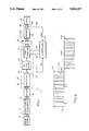
- FIG. 1 is a block diagram of an electrical power system including an inverter controller according to the invention
- FIG. 2 is a graph illustrating a pulse width modulated wave form
- FIG. 3 is a block diagram illustrating the controller of FIG. 1.
- an electrical power system 10 includes a main generator 12 driven by a prime mover 14 through a shaft 16.
- a prime mover 14 driven by a prime mover 14 through a shaft 16.
- an exciter and permanent magnet generator may also be driven by the prime mover 14 through the shaft 16 for providing field power to the synchronous generator 12, if necessary, as is conventional.
- the main generator 12 includes a stator, or armature, winding.
- the armature winding develops polyphase output power which is delivered through a feeder 18 to a converter 20.
- the converter 20 develops constant frequency power which is coupled through a high frequency filter 22 and output feeder 24 to an AC bus 26 for powering loads, represented typically at 28.
- the prime mover 14 is the main engine in an aircraft, and the converter 20 is part of a variable speed constant frequency (VSCF) system for delivering constant frequency power to the AC bus 26 for powering aircraft loads, as controlled by a controller 30.
- VSCF variable speed constant frequency
- the converter 20 includes an AC/DC converter 32 connected through a DC link 34 and DC link filter 36 to a DC/AC converter 38.
- the AC/DC converter 32 comprises a full wave bridge rectifier circuit of conventional construction which is operable to convert three-phase AC power to DC power.
- the DC/AC converter 38 comprises a pulse width modulation (PWM) inverter circuit.
- PWM pulse width modulation
- the structure of the PWM inverter 38 may take one of many known forms.
- the PWM inverter 38 may comprise a voltage source inverter having six power switches connected in a three-phase bridge configuration. Each of the power switches receive base drive commands from a pulse width modulation generator circuit.
- Such a PWM generator circuit develops base drive signals to control the output voltage of the PWM inverter 38 by varying the duty cycle of the PWM signals.
- the duty cycle is proportional to a duty cycle command received on a line 40 from the controller 30.
- the inverter switches are turned on and off in accordance with a pulse width modulated wave form 41, such as shown in FIG. 2, which is applied to the filter 22 which, in response thereto, provides a sin wave output 43, see FIG. 2.
- the magnitude V DC of the PWM waveform 41 represents the DC supply voltage on the DC link 34.
- the magnitude of the sin wave output 43 depends upon the DC link voltage and the duty cycle.
- the duty cycle represents the on time of the switches relative to the cycle time
- the controller 30 receives a DC link voltage signal on a line 42 from a DC link voltage sensor 44; a point of regulation voltage signal V POR on a line 46 from a voltage sensor 48 which senses actual voltage on the bus 26; and an electrical phase angle, representing angular position for each pole in a multiple machine, on a line 50 from the PWM inverter 38.
- the point of regulation voltage sensed by the sensor 48 is a function of the duty cycle, as discussed above.
- V DC is normally represented as a constant, in actuality this voltage includes a DC level of, for example, 270 volts, plus harmonics.
- the most significant harmonic is the third harmonic which is represented by the equation V 3 sin(3 ⁇ t+ ⁇ 3 ).
- the harmonics are added to the inverter output voltage and must be filtered by the high frequency filter 22. In order to reduce the size and weight of the filter 22 it is desirable to reduce the harmonic content of the PWM inverter output voltage.
- the controller 30 is operable to modulate the duty cycle command on the line 40 by the third harmonic in order to reduce the effect of the third harmonic to less than one percent.
- FIG. 3 a block diagram representation illustrates the controller 30 according to the invention.
- the signal representing the point of regulation voltage V POR on the line 46 is applied to a first summer 52.
- the first summer 52 also receives an inverter output reference signal on a line 51 representing a desired inverter output voltage selected at a block 56.
- the output of the first summer 52 is an inverter output voltage error on a line 58, representing the difference between desired output voltage and actual output voltage, which is applied to a transfer function block 60.
- the transfer function block 60 compensates the error signal in a conventional manner to provide a duty cycle reference D 0 on a line 62.
- the duty cycle reference represents a duty cycle necessary to maintain the inverter output voltage at the desired level.
- the duty cycle reference D 0 on the line 62 is applied to a first multiplier 64 and to a second summer 66, discussed below.
- the output of the second summer 66 is the duty cycle command on the line 40 which controls operation of the PWM inverter 38, see FIG. 1.
- closed loop control of output voltage is effective to maintain voltage on the AC bus
- a harmonic sensing control 68 receives the DC link voltage V DC on the line 42 and the phase angle signal on the line 50.
- the DC link voltage signal on the line 42 is fed through a low pass filter 70 to remove the harmonics and provide a DC level signal V 0 on a line 72.
- the DC link voltage signal on the line 42 is also fed to a high pass filter 74 to remove the DC content and the fundamental frequency.
- the output of the high pass filter 74 is a signal on a line 76 which represents the higher order harmonics and, particularly, the third harmonic.
- the signal on the line 76 is passed to second and third multipliers 78 and 80.
- the phase angle signal on the line 50 is applied to a sin/cos generator 82.
- the sin/cos generator 82 is a lookup table which generates sine and cosine signals corresponding to the third harmonic in accordance with the phase angle signal received on the line 50. Particularly, the generator 82 develops a sine signal on a line 84, represented by the equation sin 3 ⁇ t, and a cosine signal on a line 86, represented by the equation cos 3 ⁇ t.
- the sine and cosine signals on the lines 84 and 86 are applied to the respective second and third multipliers 78 and 80.
- the second and third multipliers 78 and 80 multiply the third harmonic from the high pass filter 74, represented by the equation V 3 sin(3 ⁇ t+ ⁇ 3 ), by the sin 3 ⁇ t and cos 3 ⁇ t, respectively.
- the output of the respective second and third multipliers 78 and 80 are applied to low pass filters 88 and 90 which are in turn coupled to respective fourth and fifth multipliers 92 and 94.
- the fourth and fifth multipliers 92 and 94 also receive the sine and cosine signals on the lines 84 and 86.
- the output of the fourth and fifth multipliers 92 and 94 are summed at a summing junction 96 which develops an output V 3 on a line 97 representing the third harmonic which is applied as the numerator to a divider 98.
- the denominator at the divider 98 represents the DC link voltage V 0 on the line 72.
- the output of the divider block 98 represents the ratio of the magnitude of the third harmonic V 3 to the DC link voltage V 0 on a line 100 which is applied to the first multiplier 64.
- the second summer 66 subtracts the signal D M on the line 102 from the duty cycle reference D 0 on the line 62 to provide a modulated duty cycle reference which comprises the duty cycle command on the line 40.
- the harmonic sensing control 68 is effective in connection with the first multiplier 64 and second summer 66 to modulate the duty cycle determined by the transfer function block 60 by the third harmonic to reduce the effect of the third harmonic from the inverter output voltage.
- controller 30 illustrated and described herein can be implemented with a software programmed microprocessor control unit, or with suitable electrical or electronic circuits, as is obvious to those skilled in the art.
- a VSCF system is provided with an AC output voltage having reduced harmonic voltage by minimizing the harmonic content in the DC link.
- the invention broadly comprehends a PWM inverter controlled in accordance with a modulated duty cycle command to provide reduced harmonic content.
Abstract
Description
Claims (18)
Priority Applications (1)
| Application Number | Priority Date | Filing Date | Title |
|---|---|---|---|
| US07/428,759 US5016157A (en) | 1989-10-30 | 1989-10-30 | VSCF system with DC link harmonics control |
Applications Claiming Priority (1)
| Application Number | Priority Date | Filing Date | Title |
|---|---|---|---|
| US07/428,759 US5016157A (en) | 1989-10-30 | 1989-10-30 | VSCF system with DC link harmonics control |
Publications (1)
| Publication Number | Publication Date |
|---|---|
| US5016157A true US5016157A (en) | 1991-05-14 |
Family
ID=23700291
Family Applications (1)
| Application Number | Title | Priority Date | Filing Date |
|---|---|---|---|
| US07/428,759 Expired - Fee Related US5016157A (en) | 1989-10-30 | 1989-10-30 | VSCF system with DC link harmonics control |
Country Status (1)
| Country | Link |
|---|---|
| US (1) | US5016157A (en) |
Cited By (21)
| Publication number | Priority date | Publication date | Assignee | Title |
|---|---|---|---|---|
| US5218520A (en) * | 1991-11-27 | 1993-06-08 | Rozman Gregory I | Vscf system with reduced dc link ripple |
| US5287288A (en) * | 1992-10-30 | 1994-02-15 | Electric Power Research Institute, Inc. | Active power line conditioner with low cost surge protection and fast overload recovery |
| WO1994010745A1 (en) * | 1992-10-30 | 1994-05-11 | Electric Power Research Institute, Inc. | Harmonic controller for an active power line conditioner |
| WO1994010743A1 (en) * | 1992-10-30 | 1994-05-11 | Electric Power Research Institute, Inc. | Load current fundamental filter with one cycle response |
| EP0598465A2 (en) * | 1992-11-16 | 1994-05-25 | International Power Machines | Method and apparatus for harmonic distortion correction |
| US5323303A (en) * | 1992-03-05 | 1994-06-21 | Alliedsignal Inc. | Active damper for EMI filter |
| US5327335A (en) * | 1992-09-28 | 1994-07-05 | Sundstrand Corporation | Harmonic feedback control for an inverter |
| US5351181A (en) * | 1993-03-12 | 1994-09-27 | Electric Power Research Institute, Inc. | Low cost active power line conditioner |
| US5351178A (en) * | 1992-10-30 | 1994-09-27 | Electric Power Research Institute, Inc. | Active power line conditioner with a derived load current fundamental signal for fast dynamic response |
| US5351180A (en) * | 1992-10-30 | 1994-09-27 | Electric Power Research Institute, Inc. | Highly fault tolerant active power line conditioner |
| US5355025A (en) * | 1992-10-30 | 1994-10-11 | Electric Power Research Institute, Inc. | Active power line conditioner with synchronous transformation control |
| US5384696A (en) * | 1992-10-30 | 1995-01-24 | Electric Power Research Institute, Inc. | Active power line conditioner with fundamental negative sequence compensation |
| WO1995003654A1 (en) * | 1993-07-20 | 1995-02-02 | Echelon Corporation | Source power coupler |
| US5465203A (en) * | 1993-06-18 | 1995-11-07 | Electric Power Research Institute, Inc. | Hybrid series active/parallel passive power line conditioner with controlled harmonic injection |
| US5886493A (en) * | 1995-02-16 | 1999-03-23 | The Kansai Electric Power Co., Inc. | Synchronous machine excitation control device for absorbing harmonics superposed onto fundamental current |
| US6246208B1 (en) * | 1998-11-20 | 2001-06-12 | Zapi S.P.A. | Method of feeding asynchronous motors with an inverter, in particular for battery-powered vehicles |
| US20060221657A1 (en) * | 2005-03-30 | 2006-10-05 | Kyocera Mita Corporation | AC-DC converting device, and electrical apparatus provided with AC-DC converting function |
| US20090086515A1 (en) * | 2006-04-24 | 2009-04-02 | Daikin Industries, Ltd. | Direct ac power converting apparatus |
| US20150035501A1 (en) * | 2013-08-02 | 2015-02-05 | Hamilton Sundstrand Corporation | Systems and methods for controlling torsional oscillation in wound field synchronous generator machines |
| CN104716853A (en) * | 2013-12-12 | 2015-06-17 | 英飞凌科技奥地利有限公司 | Ac/dc converter with clamped boost and buck modes and dc output harmonic control |
| RU2554319C1 (en) * | 2013-12-12 | 2015-06-27 | Федеральное государственное унитарное предприятие "Крыловский государственный научный центр" | Unit to control operation of three-phase inverter |
Citations (11)
| Publication number | Priority date | Publication date | Assignee | Title |
|---|---|---|---|---|
| DE266901C (en) * | ||||
| US4067057A (en) * | 1976-06-25 | 1978-01-03 | Pacific Electronic Enterprises Inc. | DC to AC switching converter |
| US4382275A (en) * | 1981-12-07 | 1983-05-03 | Sundstrand Corporation | PWM Inverter circuit |
| US4527226A (en) * | 1983-11-02 | 1985-07-02 | Sundstrand Corporation | Inverter control system for providing an easily filtered output |
| JPS6216065A (en) * | 1985-07-12 | 1987-01-24 | Toshiba Corp | Higher harmonic inhibitor for power converter |
| WO1987004023A1 (en) * | 1985-12-23 | 1987-07-02 | Sundstrand Corporation | Emi reduction circuit |
| US4763059A (en) * | 1987-06-23 | 1988-08-09 | General Electric Company | Method and apparatus for induction motor drive |
| US4812669A (en) * | 1986-06-26 | 1989-03-14 | Mitsubishi Denki Kabushiki Kaisha | Harmonic suppressing device |
| DE3832922A1 (en) * | 1987-09-28 | 1989-04-06 | Toshiba Kawasaki Kk | DEVICE FOR ENERGY FORMING WITH HARMONIC FILTERING |
| JPH0238455A (en) * | 1988-06-18 | 1990-02-07 | Basf Ag | Thermosetting composition having good storage stability and preparation of film therefrom |
| US4906860A (en) * | 1987-11-16 | 1990-03-06 | Mitsubishi Denki Kabushiki Kaisha | Control device for active filter |
-
1989
- 1989-10-30 US US07/428,759 patent/US5016157A/en not_active Expired - Fee Related
Patent Citations (11)
| Publication number | Priority date | Publication date | Assignee | Title |
|---|---|---|---|---|
| DE266901C (en) * | ||||
| US4067057A (en) * | 1976-06-25 | 1978-01-03 | Pacific Electronic Enterprises Inc. | DC to AC switching converter |
| US4382275A (en) * | 1981-12-07 | 1983-05-03 | Sundstrand Corporation | PWM Inverter circuit |
| US4527226A (en) * | 1983-11-02 | 1985-07-02 | Sundstrand Corporation | Inverter control system for providing an easily filtered output |
| JPS6216065A (en) * | 1985-07-12 | 1987-01-24 | Toshiba Corp | Higher harmonic inhibitor for power converter |
| WO1987004023A1 (en) * | 1985-12-23 | 1987-07-02 | Sundstrand Corporation | Emi reduction circuit |
| US4812669A (en) * | 1986-06-26 | 1989-03-14 | Mitsubishi Denki Kabushiki Kaisha | Harmonic suppressing device |
| US4763059A (en) * | 1987-06-23 | 1988-08-09 | General Electric Company | Method and apparatus for induction motor drive |
| DE3832922A1 (en) * | 1987-09-28 | 1989-04-06 | Toshiba Kawasaki Kk | DEVICE FOR ENERGY FORMING WITH HARMONIC FILTERING |
| US4906860A (en) * | 1987-11-16 | 1990-03-06 | Mitsubishi Denki Kabushiki Kaisha | Control device for active filter |
| JPH0238455A (en) * | 1988-06-18 | 1990-02-07 | Basf Ag | Thermosetting composition having good storage stability and preparation of film therefrom |
Cited By (32)
| Publication number | Priority date | Publication date | Assignee | Title |
|---|---|---|---|---|
| WO1993011600A1 (en) * | 1991-11-27 | 1993-06-10 | Sundstrand Corporation | Vscf system with reduced dc link ripple |
| US5218520A (en) * | 1991-11-27 | 1993-06-08 | Rozman Gregory I | Vscf system with reduced dc link ripple |
| US5323303A (en) * | 1992-03-05 | 1994-06-21 | Alliedsignal Inc. | Active damper for EMI filter |
| US5327335A (en) * | 1992-09-28 | 1994-07-05 | Sundstrand Corporation | Harmonic feedback control for an inverter |
| US5345377A (en) * | 1992-10-30 | 1994-09-06 | Electric Power Research Institute, Inc. | Harmonic controller for an active power line conditioner |
| US5351180A (en) * | 1992-10-30 | 1994-09-27 | Electric Power Research Institute, Inc. | Highly fault tolerant active power line conditioner |
| WO1994010743A1 (en) * | 1992-10-30 | 1994-05-11 | Electric Power Research Institute, Inc. | Load current fundamental filter with one cycle response |
| WO1994010745A1 (en) * | 1992-10-30 | 1994-05-11 | Electric Power Research Institute, Inc. | Harmonic controller for an active power line conditioner |
| AU669587B2 (en) * | 1992-10-30 | 1996-06-13 | Electric Power Research Institute, Inc. | Harmonic controller for an active power line conditioner |
| AU670137B2 (en) * | 1992-10-30 | 1996-07-04 | Electric Power Research Institute, Inc. | Load current fundamental filter with one cycle response |
| US5351178A (en) * | 1992-10-30 | 1994-09-27 | Electric Power Research Institute, Inc. | Active power line conditioner with a derived load current fundamental signal for fast dynamic response |
| US5287288A (en) * | 1992-10-30 | 1994-02-15 | Electric Power Research Institute, Inc. | Active power line conditioner with low cost surge protection and fast overload recovery |
| US5355025A (en) * | 1992-10-30 | 1994-10-11 | Electric Power Research Institute, Inc. | Active power line conditioner with synchronous transformation control |
| US5359275A (en) * | 1992-10-30 | 1994-10-25 | Electric Power Research Institute, Inc. | Load current fundamental filter with one cycle response |
| US5384696A (en) * | 1992-10-30 | 1995-01-24 | Electric Power Research Institute, Inc. | Active power line conditioner with fundamental negative sequence compensation |
| EP0598465A3 (en) * | 1992-11-16 | 1994-11-30 | Int Power Machines | Method and apparatus for harmonic distortion correction. |
| EP0598465A2 (en) * | 1992-11-16 | 1994-05-25 | International Power Machines | Method and apparatus for harmonic distortion correction |
| US5351181A (en) * | 1993-03-12 | 1994-09-27 | Electric Power Research Institute, Inc. | Low cost active power line conditioner |
| US5465203A (en) * | 1993-06-18 | 1995-11-07 | Electric Power Research Institute, Inc. | Hybrid series active/parallel passive power line conditioner with controlled harmonic injection |
| WO1995003654A1 (en) * | 1993-07-20 | 1995-02-02 | Echelon Corporation | Source power coupler |
| US5391932A (en) * | 1993-07-20 | 1995-02-21 | Echelon Corporation | Source power coupler |
| US5886493A (en) * | 1995-02-16 | 1999-03-23 | The Kansai Electric Power Co., Inc. | Synchronous machine excitation control device for absorbing harmonics superposed onto fundamental current |
| US6246208B1 (en) * | 1998-11-20 | 2001-06-12 | Zapi S.P.A. | Method of feeding asynchronous motors with an inverter, in particular for battery-powered vehicles |
| US20060221657A1 (en) * | 2005-03-30 | 2006-10-05 | Kyocera Mita Corporation | AC-DC converting device, and electrical apparatus provided with AC-DC converting function |
| US7123491B1 (en) * | 2005-03-30 | 2006-10-17 | Kyocera Mita Corporation | AC-DC converting device, and electrical apparatus provided with AC-DC converting function |
| US20090086515A1 (en) * | 2006-04-24 | 2009-04-02 | Daikin Industries, Ltd. | Direct ac power converting apparatus |
| US20150035501A1 (en) * | 2013-08-02 | 2015-02-05 | Hamilton Sundstrand Corporation | Systems and methods for controlling torsional oscillation in wound field synchronous generator machines |
| US9143070B2 (en) * | 2013-08-02 | 2015-09-22 | Hamilton Sundstrand Corporation | Systems and methods for controlling torsional oscillation in wound field synchronous generator machines |
| CN104716853A (en) * | 2013-12-12 | 2015-06-17 | 英飞凌科技奥地利有限公司 | Ac/dc converter with clamped boost and buck modes and dc output harmonic control |
| RU2554319C1 (en) * | 2013-12-12 | 2015-06-27 | Федеральное государственное унитарное предприятие "Крыловский государственный научный центр" | Unit to control operation of three-phase inverter |
| US9455620B2 (en) * | 2013-12-12 | 2016-09-27 | Infineon Technologies Austria Ag | AC/DC converter with clamped boost and buck modes and DC output harmonic control |
| CN104716853B (en) * | 2013-12-12 | 2018-02-13 | 英飞凌科技奥地利有限公司 | The AC/DC converters controlled with clamping voltage boosting and decompression mode and DC output harmonic waves |
Similar Documents
| Publication | Publication Date | Title |
|---|---|---|
| US5016157A (en) | VSCF system with DC link harmonics control | |
| EP0174741B1 (en) | Control system for permanent magnet synchronous motor | |
| US4908565A (en) | Power generating system | |
| US4361791A (en) | Apparatus for controlling a PWM inverter-permanent magnet synchronous motor drive | |
| US5029263A (en) | Electric start control of a VSCF system | |
| US5245525A (en) | DC current control through an interphase transformer using differential current sensing | |
| EP0629038B1 (en) | AC motor control | |
| US5281905A (en) | Induction machine based hybrid aircraft engine starting/generating power system | |
| US4949021A (en) | Variable speed constant frequency start system with selectable input power limiting | |
| US5055764A (en) | Low voltage aircraft engine starting system | |
| US4841216A (en) | Engine start type VSCF generating system | |
| US4066938A (en) | Input current modulation to reduce torque pulsations in controlled current inverter drives | |
| KR100437932B1 (en) | Multi-output power conversion circuit | |
| US5036267A (en) | Aircraft turbine start from a low voltage battery | |
| JP3435104B2 (en) | Apparatus and method for generating braking torque in an AC drive | |
| US5587641A (en) | VSCF start system with precise voltage control | |
| US7619327B2 (en) | Hybrid electromechanical power transfer system | |
| US4937508A (en) | VSCF start system with precision voltage | |
| EP0000530A1 (en) | Feedback control for reduction of cogging torque in controlled current AC motor drives and method | |
| CA2635443C (en) | Generating system with a regulated permanent magnet machine and an active rectifier | |
| JPS61236389A (en) | Magnetic flux control for induction motor driver using load commutation type inverter circuit | |
| US5038095A (en) | Control for a DC link power conversion system | |
| US5777459A (en) | Induction electrical power generating system with variable numbers of poles and excitation frequency | |
| US5006768A (en) | Synchronous motor control | |
| US5111376A (en) | Voltage balancing circuit |
Legal Events
| Date | Code | Title | Description |
|---|---|---|---|
| AS | Assignment |
Owner name: SUNDSTRAND CORPORATION, ILLINOIS Free format text: ASSIGNMENT OF ASSIGNORS INTEREST.;ASSIGNOR:ROZMAN, GREGORY I.;REEL/FRAME:005206/0892 Effective date: 19891011 Owner name: SUNDSTRAND CORPORATION, ILLINOIS Free format text: ASSIGNMENT OF ASSIGNORS INTEREST.;ASSIGNOR:MADDALI, VIJAY K.;REEL/FRAME:005206/0891 Effective date: 19891012 |
|
| FEPP | Fee payment procedure |
Free format text: PAYOR NUMBER ASSIGNED (ORIGINAL EVENT CODE: ASPN); ENTITY STATUS OF PATENT OWNER: LARGE ENTITY |
|
| FPAY | Fee payment |
Year of fee payment: 4 |
|
| REFU | Refund |
Free format text: REFUND PROCESSED. MAINTENANCE FEE HAS ALREADY BEEN PAID (ORIGINAL EVENT CODE: R160); ENTITY STATUS OF PATENT OWNER: LARGE ENTITY |
|
| FPAY | Fee payment |
Year of fee payment: 8 |
|
| REMI | Maintenance fee reminder mailed | ||
| LAPS | Lapse for failure to pay maintenance fees | ||
| STCH | Information on status: patent discontinuation |
Free format text: PATENT EXPIRED DUE TO NONPAYMENT OF MAINTENANCE FEES UNDER 37 CFR 1.362 |
|
| FP | Lapsed due to failure to pay maintenance fee |
Effective date: 20030514 |
|
| FEPP | Fee payment procedure |
Free format text: PAYOR NUMBER ASSIGNED (ORIGINAL EVENT CODE: ASPN); ENTITY STATUS OF PATENT OWNER: LARGE ENTITY Free format text: PAYER NUMBER DE-ASSIGNED (ORIGINAL EVENT CODE: RMPN); ENTITY STATUS OF PATENT OWNER: LARGE ENTITY |