US5023534A - Automatic guided vehicle, method for positioning said vehicle, and loading table having positioning device - Google Patents

Automatic guided vehicle, method for positioning said vehicle, and loading table having positioning device Download PDF

Info

Publication number
US5023534A
US5023534A US07/289,400 US28940088A US5023534A US 5023534 A US5023534 A US 5023534A US 28940088 A US28940088 A US 28940088A US 5023534 A US5023534 A US 5023534A
Authority
US
United States
Prior art keywords
guided vehicle
positioning
loading table
automatic guided
eccentric cams
Prior art date
Legal status (The legal status is an assumption and is not a legal conclusion. Google has not performed a legal analysis and makes no representation as to the accuracy of the status listed.)
Expired - Fee Related
Application number
US07/289,400
Inventor
Satoshi Ueda
Masahiro Sudare
Yasuyuki Suyama
Kazuhiko Kishimoto
Kenshi Suzuki
Shiroh Inoue
Shunji Sakura
Current Assignee (The listed assignees may be inaccurate. Google has not performed a legal analysis and makes no representation or warranty as to the accuracy of the list.)
Tsubakimoto Chain Co
Original Assignee
Tsubakimoto Chain Co
Priority date (The priority date is an assumption and is not a legal conclusion. Google has not performed a legal analysis and makes no representation as to the accuracy of the date listed.)
Filing date
Publication date
Priority claimed from JP63010406A external-priority patent/JP2521508B2/en
Priority claimed from JP63012842A external-priority patent/JPH0753504B2/en
Priority claimed from JP1284188A external-priority patent/JPH01186459A/en
Application filed by Tsubakimoto Chain Co filed Critical Tsubakimoto Chain Co
Assigned to TSUBAKIMOTO CHAIN CO., A CORP. OF JAPAN reassignment TSUBAKIMOTO CHAIN CO., A CORP. OF JAPAN ASSIGNMENT OF ASSIGNORS INTEREST. Assignors: INOUE, SHIROH, KISHIMOTO, KAZUHIKO, SAKURA, SHUNJI, SUDARE, MASAHIRO, SUYAMA, YASUYUKI, SUZUKI, KENSHI, UEDA, SATOSHI
Application granted granted Critical
Publication of US5023534A publication Critical patent/US5023534A/en
Anticipated expiration legal-status Critical
Expired - Fee Related legal-status Critical Current

Links

Images

Classifications

    • GPHYSICS
    • G05CONTROLLING; REGULATING
    • G05DSYSTEMS FOR CONTROLLING OR REGULATING NON-ELECTRIC VARIABLES
    • G05D1/00Control of position, course or altitude of land, water, air, or space vehicles, e.g. automatic pilot
    • G05D1/02Control of position or course in two dimensions
    • G05D1/021Control of position or course in two dimensions specially adapted to land vehicles
    • G05D1/0231Control of position or course in two dimensions specially adapted to land vehicles using optical position detecting means
    • G05D1/0234Control of position or course in two dimensions specially adapted to land vehicles using optical position detecting means using optical markers or beacons
    • GPHYSICS
    • G05CONTROLLING; REGULATING
    • G05DSYSTEMS FOR CONTROLLING OR REGULATING NON-ELECTRIC VARIABLES
    • G05D1/00Control of position, course or altitude of land, water, air, or space vehicles, e.g. automatic pilot
    • G05D1/02Control of position or course in two dimensions
    • G05D1/021Control of position or course in two dimensions specially adapted to land vehicles
    • G05D1/0231Control of position or course in two dimensions specially adapted to land vehicles using optical position detecting means
    • G05D1/0246Control of position or course in two dimensions specially adapted to land vehicles using optical position detecting means using a video camera in combination with image processing means

Definitions

  • the present invention relates generally to an apparatus and method for positioning an automatic guided vehicle having a loading table. More specifically, the present invention relates to an apparatus and method for using the loading table of the automatic guided vehicle to compensate for detected positioning errors of the automatic guided vehicle.
  • the conventional automatic guided vehicle has been provided with a table which is loaded with articles to be conveyed, disposed on the top of the vehicle, and conveys the load of articles to stations provided for various processes.
  • the articles are automatically transferred from the automatic guided vehicle to every station by a unloading device provided in the station.
  • linear and angular degrees of precision in stoppage of the automatic guided vehicle are in the order of ⁇ 10 mm in the advance direction as well as in the direction intersecting therewith and ⁇ 1° or so in the rotational direction around a vertical axis, respectively, and relative degrees of precision in stoppage between the unloading device and the loading table have an equal value with those described above, because of dependence thereof on the degree of precision in stoppage of the automatic guided vehicle.
  • deviation occurs between relative stop positions of said unloading device and of the loading table and regular relative stop positions. Therefore, it is required to provide a structure for eliminating said positional deviation for the unloading device or the automatic guided vehicle or to improve stoppage precision of the vehicle such as in the case of automatic unloading of articles in the semiconductor manufacturing factory.
  • a plurality of hydraulic jacks are provided for the automatic guided vehicle, conical holes are drilled in rod parts of the jacks, a plurality of conical positioning projections to be engaged with said holes are provided at the regular stop positions on the floors of every station correspondingly to setting positions of the hydraulic jacks, and, upon stoppage of the automatic guided vehicle at the station, the hydraulic jacks are moved forward to be fitted on the respective positioning projections for positioning the vehicle.
  • the automatic guided vehicle is lifted the floor and positioned in the correct position.
  • the positioning projections are obstructive to running of the vehicle and a large number of additional devices such as a hydraulic generating source are required, thereby inviting price increase and more complicated structure.
  • additional devices such as a hydraulic generating source
  • Unloading devices if each provided with a structure for eliminating the aforesaid positional deviation, necessitate a large number of such structures because they are arranged in every station, thereby leading to price increase of the whole system.
  • the present invention has been designed in order to solve the problems in the conventional art and a first object thereof is to provide an automatic guided vehicle, while preparing a loading table having positioning means in three directions including two on a horizontal plane and a rotational one around a vertical axis for the automatic guided vehicle, which has a simple in structure and is capable of determining relative positions of the loading table and a unloading device at low cost and with high precision.
  • a second object of the present invention is to provide a method for determining relative positions of the unloading device and the loading table by means of a simple structure without attendant, at low cost, and with high precision by detecting positioning marks provided at stop positions and positional deviation between the guided vehicle and the positioning marks, computing positioning correction values in order to eliminate said deviation, and positioning the loading table on the basis of computed positioning correction values.
  • a third object of the present invention is to provide a loading table capable of determining a stop position with high precision at low cost, nevertheless by using component parts with low precision, without polluting a clean atmosphere by using eccentric cams preloaded upon outer peripheries thereof for positioning the loading table of the automatic guided vehicle in three directions including two on a horizontal plane and a rotational one around a vertical axis.
  • FIG. 1 is a view of the left side of an automatic guided vehicle of the present invention
  • FIG. 2 is a partially broken side view of positioning means for a loading table
  • FIG. 3 is an enlarged perspective view of a state in which an eccentric cam is set
  • FIG. 4 is a block diagram showing the structure of a positioning control device of the present invention.
  • FIG. 5 is a flow chart showing the flow of control operation.
  • FIG. 6 is a diagram showing a method of computing values required for positioning.
  • FIG. 1 is a view showing the left side of an automatic guided vehicle according to the present invention, in which the advance direction of the vehicle is shown by a hollow arrow mark.
  • the reference numeral 1 indicates a body of the vehicle supported by a pair of driving wheels 2 disposed on the right and left sides of the vehicle (the one on the right side is not shown) and four subsidiary wheels 3 on the front, rear, right, and left sides (the two on the right side are not shown).
  • the driving wheels 2 are fixed to the right and the left sides of the central part of the body 1 while appropriately spaced from each other and coaxially connected to respective driving motors not shown, and the body 1 is steered with individual driving of the motors whereas driven forward and rearward with simultaneous driving.
  • the subsidiary wheels 3 are fixed to the body 1 at the front, rear, right, and left sides thereof rotatably around respective vertical axes while appropriately spaced from each other.
  • a loading table 4 for loading with articles to be conveyed is provided on the top of the body 1 coaxially therewith and fixed to the body 1 displaceably and rotatably with respect to the body 1 in three directions with positioning means 5x, 5y, and 5 ⁇ which are disposed in the central part of the body 1 and positioned in three directions including two in the advance direction of the body 1 and the direction intersecting therewith, and the rotational one around the vertical axis of the body 1, respectively.
  • Positioning means 5x, 5y, and 5 ⁇ can be driven by driving parts 6x, 6y, and 6 ⁇ , respectively, for driving in the respective three directions.
  • optical sensors 7 A , 7 B each comprising an industrial TV camera for detecting a stop position of the body 1 are downwardly fixed to the central part of the body 1 at the front and rear thereof each being distant by length L from the center of the body 1, which indicate a stop position of the body 1 for each process with the optical sensors 7 A , 7 B which pick-up images of two circular black positioning marks 8 on the centers of white squares on the floor and spaced from each other at a distance equal to that between the optical sensors 7 A , 7 B .
  • a positioning control device 9 which emits driving signals correspondingly to positions of the detected positioning marks 8 toward the driving parts 6x, 6y, and 6 ⁇ is incorporated in the body 1.
  • FIG. 2 is a partially broken side view showing positioning means each provided with a driving part for the loading table, wherein positioning means 5x, 5y, and 5 ⁇ are fixed to the central part of the body 1 at the front and the rear thereof and a base 57 thereof are tightly fixed to two brackets 12, 12, each in such a shape that a square flat plate is secured to the center of an inverted-L-shaped vertical member, which extend longitudinally intersecting the advance direction of the body 1.
  • the base 57 has a shape like a regular square flat plate having sides slightly shorter than the crosswise length of the loading table and is provided with a cylindrical boss part at the upper side of the central part.
  • the boss part incorporates a turning bearing 52 ⁇ , and a driving motor 66 ⁇ comprising a stepping motor for turning is fixed to the lower side of the rear central portion of the base 57 in such manner that the output shaft thereof is directed upward.
  • an eccentric shaft 62 ⁇ having a fixed rate of eccentricity with respect to said output shaft is connected through a flexible joint 61 ⁇ and two ball bearings 63 ⁇ as eccentric cams are externally fitted on the upper end of the eccentric shaft 62 ⁇ .
  • a cylindrical bearing box 64 ⁇ having a flange at the lower part is fixed to the upper side of the rear central part of the base 57 concentrically with the driving motor 66 ⁇ , and the eccentric shaft 62 ⁇ is supported by two ball bearings 65 ⁇ internally fitted in the upper end of the bearing box 64 ⁇ , whereby a turning table 50 ⁇ that will be described later turns around a turning bearing 52 ⁇ correspondingly to the rate of eccentricity of the eccentric shaft 62 ⁇ .
  • a downwardly directed and centrally disposed boss part of the turning table 50 ⁇ in the shape of a flat plate whose external appearance is almost the same as that of the base 57 is fitted into the inner ring of the turning bearing 52 ⁇ and the turning table 50 ⁇ can be rotated by the turning bearing 52 ⁇ while centered thereat in the rotational direction (hereinafter referred to as ⁇ direction) around the vertical axis of the body 1.
  • a cylindrical bearing box 64x having flanges at the upper and lower ends is fixed to the lower part of the front central portion of the turning table 50 ⁇ and a driving motor 66x comprising a stepping motor for displacement in the back-and-forth direction (hereinafter referred to as x direction) is fixed to the lower flange in such manner that the output shaft of the motor is directed upward.
  • x direction a driving motor 66x comprising a stepping motor for displacement in the back-and-forth direction
  • the eccentric shaft 62x is supported by two ball bearings 65x internally fitted into the upper part of the bearing box 64x and a movable table 50x that will be described later runs in the x direction correspondingly to the rate of eccentricity of the eccentric shaft 62x.
  • Four displacement guides 52x comprising rail parts of the linear guides are fixed to the turning table 50 ⁇ at the front, rear, right, and left sides thereof while appropriately spaced from each other so that the longitudinal direction thereof extends along the direction approximately agreeing with the x direction of the body 1.
  • FIG. 3 is an enlarged perspective view of a state in which an eccentric cam as driving means of the loading table is secured to an assemblage, wherein one of ball bearings 63 ⁇ serving as eccentric cams is internally fitted into a square flat lower cam receiver 54 ⁇ having a projection like a square bar at one end and being provided with an eccentric-cam receiving oblong groove 59 ⁇ whose lengthwise direction is the same as that of said bar-like projection as well as fitted into an upper cam receiver 53 ⁇ disposed above the lower cam receiver 54 ⁇ and provided with the same eccentric-cam receiving groove 58 ⁇ as that of the lower cam receiver 54 ⁇ , and the upper cam receiver 53 ⁇ is made slidable relative to the lower cam receiver 54 ⁇ in the direction perpendicular to the longitudinal direction of the eccentric-cam receiving groove by adjusting screws 55 ⁇ being engaged with threads provided in the projections of the lower cam receiver 54 ⁇ and spaced appropriately from each other longitudinally along the projection.
  • the lower and upper cam receivers 54 ⁇ and 53 ⁇ , respectively, are adjusted to preload upon outer rings thereof in such a way that the outer ring of the upper one of the two ball bearings 63 ⁇ serving as eccentric cams is pressed to the side of the eccentric-cam receiving groove 58 ⁇ from which the adjusting bolts 55 ⁇ protrude whereas the outer ring of the lower ball bearing 63 ⁇ is pressed to the side of the eccentric-cam groove 59 ⁇ of the lower cam receiver 54 ⁇ opposite to said side.
  • turning of the adjusting bolts 55 ⁇ is stopped with lock nuts 56 ⁇ .
  • the lower and upper cam receivers 54 ⁇ and 53 ⁇ , respectively, are secured to the central rear part of the turning table 50 ⁇ .
  • upper guides 51x which comprise rolling parts of linear guides engaging with moving guides 52x fixed to the turning table 50 ⁇ and rolling with respect to these moving guides 52x are fixed to the lower part of the moving table 50x so that the moving table 50x may be rolled with respect to the turning table 50 ⁇ in x direction.
  • the moving table 50x being flat with substantially the same external appearance as the turning table 50 ⁇ is fitted with, at the central lower part on the left side, a cylindrical bearing box 64y having fitting flanges at the upper and lower parts thereof.
  • a driving motor 66y comprising a stepping motor for movement in the direction perpendicular to the advance direction of the body 1, that is, the right-to-left direction of the body 1 or vice versa (hereinafter referred to as y direction), is secured with the output shaft thereof directed upward.
  • An eccentric shaft 62y having a fixed rate of eccentricity with respect to the output shaft of the driving motor 66y is connected to the forward end of the driving motor 66y through a flexible bearing 61y, and two ball bearings 63y as eccentric cams are externally fitted on the upper end of the eccentric shaft 62y.
  • the eccentric shaft 62y is bearingly supported by two ball bearings 65y fitted into the upper part of the bearing box 64y and a moving table 50y that will be described later moves in the y direction correspondingly to the eccentricity of the eccentric shaft 62y.
  • An upper cam receiver 53x and a lower one 54x being structurally identical with the upper cam receiver 53 ⁇ and the lower one 54 ⁇ , respectively, being fixed to the turning table 50 ⁇ are fixed to the upper forward central part of the moving table 50x so that the longitudinal direction of eccentric-cam grooves 58x, 59x extends in the y direction.
  • four moving guides 52y comprising rail parts of the linear guides and moving in the y direction are fixed to the front, rear, right, and left upper parts of the moving table 50x while appropriately spaced from each other.
  • Four upper guides 51y comprising rolling parts of the linear guides are fixed to the lower part of the flat square moving table 50y so as to engage with the moving guides 52y and to adapt the moving table 50y to be rollable in the y direction.
  • An upper cam receiver 53y and the lower one 54y engaging with the ball bearings 63y, 63y and structurally identical with the upper cam receiver 53 ⁇ and the lower one 54 ⁇ , respectively, are fixed to the left side lower central part of the moving table 50y so that the lengthwise direction of the eccentric-cam grooves 58y, 59y thereof extends in the x direction and the upper and lower ends thereof are inverted with respect to those of the upper and lower cam receivers 53 ⁇ and 54 ⁇ , respectively.
  • a loading part 41 composing a loading table 4 for loading articles is fixed to the top of the moving table 50y.
  • FIG. 4 is a block diagram showing a structure of the positioning control device of the automatic guided vehicle of the present invention.
  • the positioning control device 9 is provided with a position detecting part 91 for detecting positions of the positioning marks 8 whose images have been picked up by the optical sensors 7 A , 7 B , a positioning correction value computing part 92 for computing values of deviation degrees between each positions P A , P B of centers of visual fields of the optical sensor and each positions P A ', P B ' of gravitational centers of the detected positioning marks 8 and for computing positioning correction values ⁇ x, ⁇ y, and ⁇ , ⁇ in the direction x, y, and ⁇ based on the computation for positioning the loading table 4 of the automatic guided vehicle in the direction which corrects said positional error, and a motor driving part 93 for memorizing relations between each computed positioning correction values ⁇ x, ⁇ y, and ⁇ , ⁇ and each numbers of pulses to be given to the driving motors 66x, 66y, and 66 ⁇ , respectively, and, based
  • the positioning correction values ⁇ x, ⁇ y, and ⁇ , ⁇ are to be given to the driving parts 6x, 6y, and 6 ⁇ of the loading table 4 for adapting the central position G of the loading table and a setting direction x thereof to agree with an intermediate position G' between the positioning marks 8 and the direction in which these marks are set, respectively, whereby said positional error is eliminated.
  • FIG. 5 is a flow chart showing the flow of control process and FIG. 6 is a view showing a method for computing positioning correction values.
  • the automatic guided vehicle is automatically driven by a given guiding device toward stations being provided in various processes and stopped at a position enabling black circles as centers of the positioning marks 8 to be caught in the visual fields of the optical sensors 7 A , and 7 B .
  • the optical sensors 7 A , 7 B pick-up images of the positioning marks 8 and, based on the result of image picking-up, distances d XA , d YA , d XB and d YB between the central positions PA, PB and positioning marks P A ', P B ' are calculated by a position detecting part 91 in the coordinate system in which the intermediate position G' between positioning marks 8 is defined as an initial point, and setting direction of the marks as the X' axis whereas the direction perpendicular to the X' axis is defined as Y' axis.
  • the positioning correction value computing part 92 computes positioning correction values ⁇ x, ⁇ y, and ⁇ , ⁇ with values of distance d XA , d XB , d YA , and d YB obtained by the position detecting part 91, in accordance with a computing method that will be described later.
  • the motor driving part 93 converts the positioning correction values ⁇ x, ⁇ y, and ⁇ , ⁇ into the required pulse numbers Lx, Ly, and L ⁇ for driving motors 66x, 66y, and 66 ⁇ and outputs these pulse numbers to the driving motors, thereby, the loading table 4 is positioned.
  • Positioning correction values are found in accordance with the following formulae. ##EQU1## where: 2L: a distance between setting positions of positioning marks 8.
  • Positioning correction values ⁇ x, ⁇ y, and ⁇ , ⁇ are computed in accordance with the above formulae (1) to (3) and fixed numbers of pulses Lx, Ly, and L ⁇ corresponding to the above correction values are outputted by the motor driving part 93 to drive the driving motors 66x, 66y, and 66 ⁇ so as to position the loading table in the correct stop position.
  • Degrees of the movement and turning in the three directions corresponding to the rates of eccentricity are large enough with respect to the degree of deviation ( ⁇ 15 mm in the x direction, ⁇ 20 mm in the y direction, and ⁇ 2° in the ⁇ direction in this embodiment) and, even when the precision in stopping the guided vehicle is insufficient, the precision in relative position between the loading table and the loading device can be controlled to be within ⁇ 1 mm in the directions x and y as well as within the allowance in the ⁇ direction.
  • eccentric cams each provided with a ball bearing undergoing external potential pressure at the outer ring thereof are used, a structure of positioning means is simple and backlash between the eccentric cam and the groove therefor is suppressed to ensure smooth positioning.
  • cam mechanism as positioning means as used in this embodiment is not necessarily required for the first and second inventive items of the present invention and any mechanism such as using rack pinions, ball screws, or others may suffice as far as being capable of positioning in the three directions x, y, and ⁇ .
  • a stepping motor is used as a driving motor in this embodiment, however, any kind of motor capable of position-controlling such as a servomotor equipped with an encoder may fulfill the purpose for any of three inventive items of the present invention.
  • the optical sensors are disposed at equal distances from the center of the body of the vehicle, however, it is needless to say that they may be located in any position with respect to the body of the vehicle as far as being capable of detecting the aforesaid degree of positional deviation.
  • positioning means capable of positioning the loading table with high precision in three directions including two on a horizontal plane and a rotational one around a vertical axis are provided, the optical sensors detect degrees of deviation between a fixed stop position and a stop position of the guided vehicle, positioning correction values in the three directions are computed based on the result of detection for positioning of the loading table, whereby positioning of the automatic guided vehicle can be performed with a simple structure without requiring attendant at low cost with high precision.
  • the loading table is provided with a positioning device with high precision in three directions including two on a horizontal plane and a rotational one around a vertical axis, therefore, a stop point of the loading table can be positioned with high precision by a simple structure at low cost.
  • positioning in three directions including two on a horizontal plane and a rotational one around a vertical axis is performed by the driving parts using eccentric cams whose outer peripheries are subjected to external potential pressure, whereby a stop point can be positioned by a structure having small size, light weight, and high precision at low cost.

Abstract

An automatic guided vehicle comprising a loading table provided with positioning motors for three directions including two on a horizontal plane and a rotational one around a vertical axis and also with optical sensors for detecting positioning marks at stop positions so that positioning of the automatic guided vehicle at a stop point thereof may be ensured in high precision, and a method for positioning the automatic guided vehicle without attendant with high precision in such manner that the optical sensors detect degrees of deviation between the guided vehicle and the positioning marks, and positioning motors are driven after computing three-directional positioning correction values based on the result of detection or reducing deviation at the loading table.

Description

BACKGROUND OF THE INVENTION
1. Field of the Invention
The present invention relates generally to an apparatus and method for positioning an automatic guided vehicle having a loading table. More specifically, the present invention relates to an apparatus and method for using the loading table of the automatic guided vehicle to compensate for detected positioning errors of the automatic guided vehicle.
2. Description of the Prior Art
Automatic guided vehicles have greatly been developed as nucleating apparatus of factory automation for these several years.
The conventional automatic guided vehicle has been provided with a table which is loaded with articles to be conveyed, disposed on the top of the vehicle, and conveys the load of articles to stations provided for various processes. The articles are automatically transferred from the automatic guided vehicle to every station by a unloading device provided in the station.
On the other hand, linear and angular degrees of precision in stoppage of the automatic guided vehicle are in the order of ±10 mm in the advance direction as well as in the direction intersecting therewith and ±1° or so in the rotational direction around a vertical axis, respectively, and relative degrees of precision in stoppage between the unloading device and the loading table have an equal value with those described above, because of dependence thereof on the degree of precision in stoppage of the automatic guided vehicle. Together with precision error at the time of stoppage, deviation occurs between relative stop positions of said unloading device and of the loading table and regular relative stop positions. Therefore, it is required to provide a structure for eliminating said positional deviation for the unloading device or the automatic guided vehicle or to improve stoppage precision of the vehicle such as in the case of automatic unloading of articles in the semiconductor manufacturing factory.
As known measures for improving stoppage precision, there is positioning means of such structure that a plurality of hydraulic jacks are provided for the automatic guided vehicle, conical holes are drilled in rod parts of the jacks, a plurality of conical positioning projections to be engaged with said holes are provided at the regular stop positions on the floors of every station correspondingly to setting positions of the hydraulic jacks, and, upon stoppage of the automatic guided vehicle at the station, the hydraulic jacks are moved forward to be fitted on the respective positioning projections for positioning the vehicle. Thus, the automatic guided vehicle is lifted the floor and positioned in the correct position.
However, in said measures, the positioning projections are obstructive to running of the vehicle and a large number of additional devices such as a hydraulic generating source are required, thereby inviting price increase and more complicated structure. Further, such measures as mentioned above, which determine a position of the vehicle while depending on engagement of holes with projections, degrades positioning precision owing to advanced wear of holes and projections, whereby particles of worn parts are turned into dust and the vehicle could not be employed in circumstances where the degrees of positioning precision and purification are limited such as in the semiconductor manufacturing factory.
Unloading devices, if each provided with a structure for eliminating the aforesaid positional deviation, necessitate a large number of such structures because they are arranged in every station, thereby leading to price increase of the whole system.
In addition, when providing a structure for eliminating the positional deviation for the automatic guided vehicle, it is presumable that positioning in the advance direction of the vehicle and in the direction intersecting therewith depends on ball screws and that positioning in the rotational direction around a vertical axis depends on rotation of gearing mechanism, however, the mechanism using ball screws and gearing has such problems as requiring wide space for installation and a large number of parts, weight increase, and higher manufacturing cost on account of requirements for leveled up precision in component parts to obtain higher precision in the ball screw and gearing mechanisms attended with backlash. The use of the ball screws and gearing mechanism causes particulated dust of worn parts and requires dust-proof countermeasures over a wide range.
SUMMARY OF THE INVENTION
The present invention has been designed in order to solve the problems in the conventional art and a first object thereof is to provide an automatic guided vehicle, while preparing a loading table having positioning means in three directions including two on a horizontal plane and a rotational one around a vertical axis for the automatic guided vehicle, which has a simple in structure and is capable of determining relative positions of the loading table and a unloading device at low cost and with high precision.
A second object of the present invention is to provide a method for determining relative positions of the unloading device and the loading table by means of a simple structure without attendant, at low cost, and with high precision by detecting positioning marks provided at stop positions and positional deviation between the guided vehicle and the positioning marks, computing positioning correction values in order to eliminate said deviation, and positioning the loading table on the basis of computed positioning correction values.
A third object of the present invention is to provide a loading table capable of determining a stop position with high precision at low cost, nevertheless by using component parts with low precision, without polluting a clean atmosphere by using eccentric cams preloaded upon outer peripheries thereof for positioning the loading table of the automatic guided vehicle in three directions including two on a horizontal plane and a rotational one around a vertical axis.
The above and further objects and features of the invention will more fully be apparent from the following detailed description with accompanying drawings.
BRIEF DESCRIPTION OF THE DRAWINGS
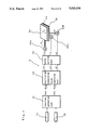
FIG. 1 is a view of the left side of an automatic guided vehicle of the present invention;
FIG. 2 is a partially broken side view of positioning means for a loading table;
FIG. 3 is an enlarged perspective view of a state in which an eccentric cam is set;
FIG. 4 is a block diagram showing the structure of a positioning control device of the present invention;
FIG. 5 is a flow chart showing the flow of control operation; and
FIG. 6 is a diagram showing a method of computing values required for positioning.
DESCRIPTION OF THE PREFERRED EMBODIMENTS
The present invention will be described in detail with reference to the drawings showing embodiments of the invention.
FIG. 1 is a view showing the left side of an automatic guided vehicle according to the present invention, in which the advance direction of the vehicle is shown by a hollow arrow mark.
In the drawing, the reference numeral 1 indicates a body of the vehicle supported by a pair of driving wheels 2 disposed on the right and left sides of the vehicle (the one on the right side is not shown) and four subsidiary wheels 3 on the front, rear, right, and left sides (the two on the right side are not shown). The driving wheels 2 are fixed to the right and the left sides of the central part of the body 1 while appropriately spaced from each other and coaxially connected to respective driving motors not shown, and the body 1 is steered with individual driving of the motors whereas driven forward and rearward with simultaneous driving. The subsidiary wheels 3 are fixed to the body 1 at the front, rear, right, and left sides thereof rotatably around respective vertical axes while appropriately spaced from each other.
A loading table 4 for loading with articles to be conveyed is provided on the top of the body 1 coaxially therewith and fixed to the body 1 displaceably and rotatably with respect to the body 1 in three directions with positioning means 5x, 5y, and 5θ which are disposed in the central part of the body 1 and positioned in three directions including two in the advance direction of the body 1 and the direction intersecting therewith, and the rotational one around the vertical axis of the body 1, respectively. Positioning means 5x, 5y, and 5θ can be driven by driving parts 6x, 6y, and 6θ, respectively, for driving in the respective three directions.
On the other hand, optical sensors 7A, 7B each comprising an industrial TV camera for detecting a stop position of the body 1 are downwardly fixed to the central part of the body 1 at the front and rear thereof each being distant by length L from the center of the body 1, which indicate a stop position of the body 1 for each process with the optical sensors 7A, 7B which pick-up images of two circular black positioning marks 8 on the centers of white squares on the floor and spaced from each other at a distance equal to that between the optical sensors 7A, 7B. A positioning control device 9 which emits driving signals correspondingly to positions of the detected positioning marks 8 toward the driving parts 6x, 6y, and 6θ is incorporated in the body 1.
FIG. 2 is a partially broken side view showing positioning means each provided with a driving part for the loading table, wherein positioning means 5x, 5y, and 5θ are fixed to the central part of the body 1 at the front and the rear thereof and a base 57 thereof are tightly fixed to two brackets 12, 12, each in such a shape that a square flat plate is secured to the center of an inverted-L-shaped vertical member, which extend longitudinally intersecting the advance direction of the body 1.
The base 57 has a shape like a regular square flat plate having sides slightly shorter than the crosswise length of the loading table and is provided with a cylindrical boss part at the upper side of the central part. The boss part incorporates a turning bearing 52θ, and a driving motor 66θ comprising a stepping motor for turning is fixed to the lower side of the rear central portion of the base 57 in such manner that the output shaft thereof is directed upward. To the forward end of the driving motor 66θ, an eccentric shaft 62θ having a fixed rate of eccentricity with respect to said output shaft is connected through a flexible joint 61θ and two ball bearings 63θ as eccentric cams are externally fitted on the upper end of the eccentric shaft 62θ. A cylindrical bearing box 64θ having a flange at the lower part is fixed to the upper side of the rear central part of the base 57 concentrically with the driving motor 66θ, and the eccentric shaft 62θ is supported by two ball bearings 65θ internally fitted in the upper end of the bearing box 64θ, whereby a turning table 50θ that will be described later turns around a turning bearing 52θ correspondingly to the rate of eccentricity of the eccentric shaft 62θ.
A downwardly directed and centrally disposed boss part of the turning table 50θ in the shape of a flat plate whose external appearance is almost the same as that of the base 57 is fitted into the inner ring of the turning bearing 52θ and the turning table 50θ can be rotated by the turning bearing 52θ while centered thereat in the rotational direction (hereinafter referred to as θ direction) around the vertical axis of the body 1. A cylindrical bearing box 64x having flanges at the upper and lower ends is fixed to the lower part of the front central portion of the turning table 50θ and a driving motor 66x comprising a stepping motor for displacement in the back-and-forth direction (hereinafter referred to as x direction) is fixed to the lower flange in such manner that the output shaft of the motor is directed upward. To the forward end of the driving motor 66x, the eccentric shaft 62x having a fixed rate of eccentricity with respect to the output shaft of the driving motor is connected through the flexible joint 61x, and two ball bearings 63x as eccentric cams are externally fitted on the upper end of the eccentric shaft 62x. The eccentric shaft 62x is supported by two ball bearings 65x internally fitted into the upper part of the bearing box 64x and a movable table 50x that will be described later runs in the x direction correspondingly to the rate of eccentricity of the eccentric shaft 62x. Four displacement guides 52x comprising rail parts of the linear guides are fixed to the turning table 50θ at the front, rear, right, and left sides thereof while appropriately spaced from each other so that the longitudinal direction thereof extends along the direction approximately agreeing with the x direction of the body 1.
FIG. 3 is an enlarged perspective view of a state in which an eccentric cam as driving means of the loading table is secured to an assemblage, wherein one of ball bearings 63θ serving as eccentric cams is internally fitted into a square flat lower cam receiver 54θ having a projection like a square bar at one end and being provided with an eccentric-cam receiving oblong groove 59θ whose lengthwise direction is the same as that of said bar-like projection as well as fitted into an upper cam receiver 53θ disposed above the lower cam receiver 54θ and provided with the same eccentric-cam receiving groove 58θ as that of the lower cam receiver 54θ, and the upper cam receiver 53θ is made slidable relative to the lower cam receiver 54θ in the direction perpendicular to the longitudinal direction of the eccentric-cam receiving groove by adjusting screws 55θ being engaged with threads provided in the projections of the lower cam receiver 54θ and spaced appropriately from each other longitudinally along the projection. The lower and upper cam receivers 54θ and 53θ, respectively, are adjusted to preload upon outer rings thereof in such a way that the outer ring of the upper one of the two ball bearings 63θ serving as eccentric cams is pressed to the side of the eccentric-cam receiving groove 58θ from which the adjusting bolts 55θ protrude whereas the outer ring of the lower ball bearing 63θ is pressed to the side of the eccentric-cam groove 59θ of the lower cam receiver 54θ opposite to said side. After such adjustment as described above, turning of the adjusting bolts 55θ is stopped with lock nuts 56θ. The lower and upper cam receivers 54θ and 53θ, respectively, are secured to the central rear part of the turning table 50θ.
On the other hand, four upper guides 51x which comprise rolling parts of linear guides engaging with moving guides 52x fixed to the turning table 50θ and rolling with respect to these moving guides 52x are fixed to the lower part of the moving table 50x so that the moving table 50x may be rolled with respect to the turning table 50θ in x direction.
The moving table 50x being flat with substantially the same external appearance as the turning table 50θ is fitted with, at the central lower part on the left side, a cylindrical bearing box 64y having fitting flanges at the upper and lower parts thereof. To the lower fitting flange, a driving motor 66y comprising a stepping motor for movement in the direction perpendicular to the advance direction of the body 1, that is, the right-to-left direction of the body 1 or vice versa (hereinafter referred to as y direction), is secured with the output shaft thereof directed upward. An eccentric shaft 62y having a fixed rate of eccentricity with respect to the output shaft of the driving motor 66y is connected to the forward end of the driving motor 66y through a flexible bearing 61y, and two ball bearings 63y as eccentric cams are externally fitted on the upper end of the eccentric shaft 62y. The eccentric shaft 62y is bearingly supported by two ball bearings 65y fitted into the upper part of the bearing box 64y and a moving table 50y that will be described later moves in the y direction correspondingly to the eccentricity of the eccentric shaft 62y. An upper cam receiver 53x and a lower one 54x being structurally identical with the upper cam receiver 53θ and the lower one 54θ, respectively, being fixed to the turning table 50θ are fixed to the upper forward central part of the moving table 50x so that the longitudinal direction of eccentric- cam grooves 58x, 59x extends in the y direction. Further, four moving guides 52y comprising rail parts of the linear guides and moving in the y direction are fixed to the front, rear, right, and left upper parts of the moving table 50x while appropriately spaced from each other. Four upper guides 51y comprising rolling parts of the linear guides are fixed to the lower part of the flat square moving table 50y so as to engage with the moving guides 52y and to adapt the moving table 50y to be rollable in the y direction. An upper cam receiver 53y and the lower one 54y engaging with the ball bearings 63y, 63y and structurally identical with the upper cam receiver 53θ and the lower one 54θ, respectively, are fixed to the left side lower central part of the moving table 50y so that the lengthwise direction of the eccentric- cam grooves 58y, 59y thereof extends in the x direction and the upper and lower ends thereof are inverted with respect to those of the upper and lower cam receivers 53θ and 54θ, respectively. A loading part 41 composing a loading table 4 for loading articles is fixed to the top of the moving table 50y.
FIG. 4 is a block diagram showing a structure of the positioning control device of the automatic guided vehicle of the present invention. The positioning control device 9 is provided with a position detecting part 91 for detecting positions of the positioning marks 8 whose images have been picked up by the optical sensors 7A, 7B, a positioning correction value computing part 92 for computing values of deviation degrees between each positions PA, PB of centers of visual fields of the optical sensor and each positions PA ', PB ' of gravitational centers of the detected positioning marks 8 and for computing positioning correction values Δx, Δy, and Δ, θ in the direction x, y, and θ based on the computation for positioning the loading table 4 of the automatic guided vehicle in the direction which corrects said positional error, and a motor driving part 93 for memorizing relations between each computed positioning correction values Δx, Δy, and Δ, θ and each numbers of pulses to be given to the driving motors 66x, 66y, and 66θ, respectively, and, based on the above memory, for giving fixed numbers of pulses Lx, Ly, and Lθ to the driving motors 66x, 66y, and 66θ.
A method of the present invention for computing positioning correction values to be applied to control over the automatic guided vehicle and stop position thereof will be described. The positioning correction values Δx, Δy, and Δ, θ are to be given to the driving parts 6x, 6y, and 6θ of the loading table 4 for adapting the central position G of the loading table and a setting direction x thereof to agree with an intermediate position G' between the positioning marks 8 and the direction in which these marks are set, respectively, whereby said positional error is eliminated.
FIG. 5 is a flow chart showing the flow of control process and FIG. 6 is a view showing a method for computing positioning correction values. With reference to these illustrations, the automatic guided vehicle is automatically driven by a given guiding device toward stations being provided in various processes and stopped at a position enabling black circles as centers of the positioning marks 8 to be caught in the visual fields of the optical sensors 7A, and 7B. When the guided vehicle is stopped, the optical sensors 7A, 7B pick-up images of the positioning marks 8 and, based on the result of image picking-up, distances dXA, dYA, dXB and dYB between the central positions PA, PB and positioning marks PA ', PB ' are calculated by a position detecting part 91 in the coordinate system in which the intermediate position G' between positioning marks 8 is defined as an initial point, and setting direction of the marks as the X' axis whereas the direction perpendicular to the X' axis is defined as Y' axis. The positioning correction value computing part 92 computes positioning correction values Δx, Δy, and Δ, θ with values of distance dXA, dXB, dYA, and dYB obtained by the position detecting part 91, in accordance with a computing method that will be described later. The motor driving part 93 converts the positioning correction values Δx, Δy, and Δ, θ into the required pulse numbers Lx, Ly, and Lθ for driving motors 66x, 66y, and 66θ and outputs these pulse numbers to the driving motors, thereby, the loading table 4 is positioned.
On the other hand, for computing the positioning correction values Δx, Δy, and Δ, θ, the above-described values of distances dXA, dYA, dXB, and dYB are computed when gravitational centers of the positioning marks 8, 8 are taken in the visual fields of the optical sensors 7A, 7B. Positioning correction values are found in accordance with the following formulae. ##EQU1## where: 2L: a distance between setting positions of positioning marks 8.
Positioning correction values Δx, Δy, and Δ, θ are computed in accordance with the above formulae (1) to (3) and fixed numbers of pulses Lx, Ly, and Lθ corresponding to the above correction values are outputted by the motor driving part 93 to drive the driving motors 66x, 66y, and 66θ so as to position the loading table in the correct stop position. Degrees of the movement and turning in the three directions corresponding to the rates of eccentricity are large enough with respect to the degree of deviation (±15 mm in the x direction, ±20 mm in the y direction, and ±2° in the θ direction in this embodiment) and, even when the precision in stopping the guided vehicle is insufficient, the precision in relative position between the loading table and the loading device can be controlled to be within ±1 mm in the directions x and y as well as within the allowance in the θ direction.
In this embodiment, since eccentric cams each provided with a ball bearing undergoing external potential pressure at the outer ring thereof are used, a structure of positioning means is simple and backlash between the eccentric cam and the groove therefor is suppressed to ensure smooth positioning.
The cam mechanism as positioning means as used in this embodiment is not necessarily required for the first and second inventive items of the present invention and any mechanism such as using rack pinions, ball screws, or others may suffice as far as being capable of positioning in the three directions x, y, and θ.
Further, a stepping motor is used as a driving motor in this embodiment, however, any kind of motor capable of position-controlling such as a servomotor equipped with an encoder may fulfill the purpose for any of three inventive items of the present invention.
Also, in this embodiment, the optical sensors are disposed at equal distances from the center of the body of the vehicle, however, it is needless to say that they may be located in any position with respect to the body of the vehicle as far as being capable of detecting the aforesaid degree of positional deviation.
As has hitherto been described in detail, according to the method for positioning the automatic guided vehicle as the second item of the invention, positioning means capable of positioning the loading table with high precision in three directions including two on a horizontal plane and a rotational one around a vertical axis are provided, the optical sensors detect degrees of deviation between a fixed stop position and a stop position of the guided vehicle, positioning correction values in the three directions are computed based on the result of detection for positioning of the loading table, whereby positioning of the automatic guided vehicle can be performed with a simple structure without requiring attendant at low cost with high precision.
In the automatic guided vehicle as the first item of the invention, the loading table is provided with a positioning device with high precision in three directions including two on a horizontal plane and a rotational one around a vertical axis, therefore, a stop point of the loading table can be positioned with high precision by a simple structure at low cost.
In addition, in the loading table as the third item of the invention, positioning in three directions including two on a horizontal plane and a rotational one around a vertical axis is performed by the driving parts using eccentric cams whose outer peripheries are subjected to external potential pressure, whereby a stop point can be positioned by a structure having small size, light weight, and high precision at low cost.
As this invention may be embodied in several forms without departing from the spirit of essential characteristics thereof, the present embodiment is therefore illustrative and not restrictive, since the scope of the invention is defined by the appended claims rather than by the description preceding them, and all changes that fall within the meets and bounds of the claims, or equivalence of such meets and bounds thereof are therefore intended to be embraced by the claims.

Claims (9)

What is claimed is:
1. An automatic guided vehicle which runs along a predetermined running course comprising:
a loading table coupled to the guided vehicle, said guided vehicle provided with positioning means for adjusting a position of said loading table relative to said guided vehicle;
mark-detecting means, coupled to said guided vehicle, for detecting positioning marks disposed relative to said running course, said positioning marks representative of a desired orientation for said loading table;
means, coupled to said guided vehicle, for computing a first deviation between a position represented by said detected positioning marks and a position of said automatic guided vehicle, said first deviation representative of a second deviation between said desired orientation for said loading table and an actual orientation of said loading table; and
means, coupled to said loading table and said computing means, for controlling said positioning means to reduce said second deviation.
2. The automatic guided vehicle as set forth in claim 1, wherein said positioning means comprises:
a plurality of driving parts including a plurality of eccentric cams and driving devices to drive said eccentric cams for displacing said loading table relative to said guided vehicle; and
a plurality of follower parts each of which has a cam groove to preload upon an outer periphery of particular ones of said eccentric cams of said plurality of driving parts, respectively to cause said plurality of eccentric cams to turn therein.
3. The automatic guided vehicle as set forth in claim 1, wherein said mark-detecting means comprises a TV camera.
4. A method for positioning an automatic guided vehicle, comprising the steps of:
providing an automatic guided vehicle having a loading table adjustable relative to said automatic guided vehicle by a positioning means, said loading table disposed to be loaded with an article, said automatic guided vehicle automatically runs, and stops;
targeting positioning marks representative of a desired orientation of said loading table when said automatic guided vehicle stops;
detecting a first deviation between an orientation of said automatic guided vehicle and said positioning marks said first deviation representative of a second deviation between said desired orientation and an actual orientation of said loading table; and
driving said positioning means to reduce said second deviation.
5. The positioning method as set forth in claim 4, wherein said positioning means comprises:
a plurality of driving parts including a plurality of eccentric cams and driving devices to drive said eccentric cams for displacing said loading table relative to said guided vehicle; and
a plurality of follower parts each of which has a cam groove to preload an outer periphery of particular ones of said eccentric cams of said plurality of driving parts, respectively to cause said plurality of eccentric cams to turn therein.
6. The positioning method as set forth in claim 4, wherein said said targeting step is performed by a TV camera.
7. A loading table provided on an automatic guided vehicle comprising:
a turning table rotatable around a substantially vertical axis;
a first and a second moving table independently movable in two directions on a substantially horizontal plane;
a plurality of driving parts, coupled to said automatic guided vehicle, said turning table, and said first moving table, said plurality of driving parts include a plurality of eccentric cams and driving devices for rotating said eccentric cams; and
a plurality of follower parts, coupled to said turning table, said first moving table, and said second one, said plurality of follower parts have cam grooves to preload an outer periphery of particular ones of said eccentric cams of said plurality of driving parts, respectively and to cause said eccentric cams to turn therein.
8. The automatic guided vehicle of claim 1 wherein said loading table is disposed substantially in a horizontal plane and said positioning means comprises means for adjusting said loading table in said horizontal plane.
9. The automatic guided vehicle of claim 1 wherein said positioning means further comprises means for adjusting a rotational orientation of said loading table normal to said horizontal plane.
US07/289,400 1988-01-19 1988-12-22 Automatic guided vehicle, method for positioning said vehicle, and loading table having positioning device Expired - Fee Related US5023534A (en)

Applications Claiming Priority (6)

Application Number Priority Date Filing Date Title
JP63010406A JP2521508B2 (en) 1988-01-19 1988-01-19 Transport vehicle
JP63-10406 1988-01-19
JP63-12842 1988-01-22
JP63-12841 1988-01-22
JP63012842A JPH0753504B2 (en) 1988-01-22 1988-01-22 Loading platform
JP1284188A JPH01186459A (en) 1988-01-22 1988-01-22 Positioning method for carrying vehicle

Publications (1)

Publication Number Publication Date
US5023534A true US5023534A (en) 1991-06-11

Family

ID=27278953

Family Applications (1)

Application Number Title Priority Date Filing Date
US07/289,400 Expired - Fee Related US5023534A (en) 1988-01-19 1988-12-22 Automatic guided vehicle, method for positioning said vehicle, and loading table having positioning device

Country Status (1)

Country Link
US (1) US5023534A (en)

Cited By (8)

* Cited by examiner, † Cited by third party
Publication number Priority date Publication date Assignee Title
US5413450A (en) * 1993-03-31 1995-05-09 Eastman Kodak Company Apparatus for transporting a load
US5451133A (en) * 1993-03-31 1995-09-19 Eastman Kodak Company Docking apparatus
WO2001049940A1 (en) * 1999-12-31 2001-07-12 Otmar Fahrion Unit for production of track elements
US20020029672A1 (en) * 1997-03-28 2002-03-14 Raney Charles C. Web or sheet-fed apparatus having high-speed mechanism for simultaneous X, Y and theta registration
US6666122B2 (en) 1997-03-28 2003-12-23 Preco Industries, Inc. Web or sheet-fed apparatus having high-speed mechanism for simultaneous X, Y and θ registration and method
US20110110747A1 (en) * 2009-11-11 2011-05-12 Marsh Jeffrey D Apparatus for and method of trimming of perfect bound books
US8657452B2 (en) * 2011-12-16 2014-02-25 Chrysler Group Llc Laser sight cleaner
CN114543583A (en) * 2022-04-28 2022-05-27 成都航天万欣科技有限公司 Precision adjusting device and method for storage and transportation launching box

Citations (3)

* Cited by examiner, † Cited by third party
Publication number Priority date Publication date Assignee Title
US4682926A (en) * 1986-01-02 1987-07-28 Morrison-Knudsen Company, Inc. Ceiling panel placing machine
US4703240A (en) * 1985-03-07 1987-10-27 Murata Kikai Kabushki Kaisha System for guiding a driverless vehicle
US4796198A (en) * 1986-10-17 1989-01-03 The United States Of America As Represented By The United States Department Of Energy Method for laser-based two-dimensional navigation system in a structured environment

Patent Citations (3)

* Cited by examiner, † Cited by third party
Publication number Priority date Publication date Assignee Title
US4703240A (en) * 1985-03-07 1987-10-27 Murata Kikai Kabushki Kaisha System for guiding a driverless vehicle
US4682926A (en) * 1986-01-02 1987-07-28 Morrison-Knudsen Company, Inc. Ceiling panel placing machine
US4796198A (en) * 1986-10-17 1989-01-03 The United States Of America As Represented By The United States Department Of Energy Method for laser-based two-dimensional navigation system in a structured environment

Cited By (11)

* Cited by examiner, † Cited by third party
Publication number Priority date Publication date Assignee Title
US5413450A (en) * 1993-03-31 1995-05-09 Eastman Kodak Company Apparatus for transporting a load
US5451133A (en) * 1993-03-31 1995-09-19 Eastman Kodak Company Docking apparatus
US20020029672A1 (en) * 1997-03-28 2002-03-14 Raney Charles C. Web or sheet-fed apparatus having high-speed mechanism for simultaneous X, Y and theta registration
US6666122B2 (en) 1997-03-28 2003-12-23 Preco Industries, Inc. Web or sheet-fed apparatus having high-speed mechanism for simultaneous X, Y and θ registration and method
US6871571B2 (en) 1997-03-28 2005-03-29 Preco Industries, Inc. Web or sheet-fed apparatus having high-speed mechanism for simultaneous X,Y and theta registration
WO2001049940A1 (en) * 1999-12-31 2001-07-12 Otmar Fahrion Unit for production of track elements
US7174624B1 (en) 1999-12-31 2007-02-13 Otmar Fahrion Unit for production of track elements
US20110110747A1 (en) * 2009-11-11 2011-05-12 Marsh Jeffrey D Apparatus for and method of trimming of perfect bound books
US8657452B2 (en) * 2011-12-16 2014-02-25 Chrysler Group Llc Laser sight cleaner
CN114543583A (en) * 2022-04-28 2022-05-27 成都航天万欣科技有限公司 Precision adjusting device and method for storage and transportation launching box
CN114543583B (en) * 2022-04-28 2022-07-15 成都航天万欣科技有限公司 Precision adjusting device and method for storage and transportation launching box

Similar Documents

Publication Publication Date Title
US5023534A (en) Automatic guided vehicle, method for positioning said vehicle, and loading table having positioning device
US4948330A (en) Alignment stage device
US6739036B2 (en) Electric-component mounting system
KR920006482B1 (en) Part incorporating system
EP1260309A2 (en) Table system with angular position controls
US20100199797A1 (en) Transfer robot, transfer method, and control method
US20180224681A1 (en) Cell forming device and alignment method
KR100981074B1 (en) Shelving system
US4546573A (en) Grinding machine
US4959798A (en) Robotic television-camera dolly system
US3039032A (en) Error compensator for a position transducer
JP2521508B2 (en) Transport vehicle
US5201145A (en) Monocrystal ingot attitude-adjusting/surface-grinding/conveying apparatus
CN110209164B (en) Linear Hall guiding device of AGV (automatic guided vehicle) and guiding method thereof
CN110153995B (en) Method for calculating correction value of industrial robot
US6732609B2 (en) Moving apparatus and displacing apparatus
JPH0753504B2 (en) Loading platform
JPH0635538A (en) Method and device for calibration of stop position of mobile object
JPH0529579B2 (en)
EP0534765B1 (en) Parts mounting apparatus
CN110153993B (en) Method for calculating correction value of industrial robot
JPH05200649A (en) Tool centering device
JP2881889B2 (en) Transfer positioning device for automatic guided vehicles
US4688440A (en) Member for intermittent feed motion
KR102210025B1 (en) Method for adjusting industrial robot

Legal Events

Date Code Title Description
AS Assignment

Owner name: TSUBAKIMOTO CHAIN CO., 17-88, TSURUMI 4-CHOME, TSU

Free format text: ASSIGNMENT OF ASSIGNORS INTEREST.;ASSIGNORS:UEDA, SATOSHI;SUDARE, MASAHIRO;SUYAMA, YASUYUKI;AND OTHERS;REEL/FRAME:004987/0104

Effective date: 19881216

Owner name: TSUBAKIMOTO CHAIN CO., A CORP. OF JAPAN, JAPAN

Free format text: ASSIGNMENT OF ASSIGNORS INTEREST;ASSIGNORS:UEDA, SATOSHI;SUDARE, MASAHIRO;SUYAMA, YASUYUKI;AND OTHERS;REEL/FRAME:004987/0104

Effective date: 19881216

FEPP Fee payment procedure

Free format text: PAYOR NUMBER ASSIGNED (ORIGINAL EVENT CODE: ASPN); ENTITY STATUS OF PATENT OWNER: LARGE ENTITY

REMI Maintenance fee reminder mailed
LAPS Lapse for failure to pay maintenance fees
FP Lapsed due to failure to pay maintenance fee

Effective date: 19950614

STCH Information on status: patent discontinuation

Free format text: PATENT EXPIRED DUE TO NONPAYMENT OF MAINTENANCE FEES UNDER 37 CFR 1.362