US5033871A - Extrudable multi-rigidity hydrodynamic bearing and method of making the same - Google Patents
Extrudable multi-rigidity hydrodynamic bearing and method of making the same Download PDFInfo
- Publication number
- US5033871A US5033871A US07/544,933 US54493390A US5033871A US 5033871 A US5033871 A US 5033871A US 54493390 A US54493390 A US 54493390A US 5033871 A US5033871 A US 5033871A
- Authority
- US
- United States
- Prior art keywords
- bearing
- grooves
- skeletal
- pad support
- pads
- Prior art date
- Legal status (The legal status is an assumption and is not a legal conclusion. Google has not performed a legal analysis and makes no representation as to the accuracy of the status listed.)
- Expired - Fee Related
Links
Images


Classifications
-
- F—MECHANICAL ENGINEERING; LIGHTING; HEATING; WEAPONS; BLASTING
- F16—ENGINEERING ELEMENTS AND UNITS; GENERAL MEASURES FOR PRODUCING AND MAINTAINING EFFECTIVE FUNCTIONING OF MACHINES OR INSTALLATIONS; THERMAL INSULATION IN GENERAL
- F16C—SHAFTS; FLEXIBLE SHAFTS; ELEMENTS OR CRANKSHAFT MECHANISMS; ROTARY BODIES OTHER THAN GEARING ELEMENTS; BEARINGS
- F16C33/00—Parts of bearings; Special methods for making bearings or parts thereof
- F16C33/02—Parts of sliding-contact bearings
- F16C33/04—Brasses; Bushes; Linings
- F16C33/22—Sliding surface consisting mainly of rubber or synthetic rubber
-
- B—PERFORMING OPERATIONS; TRANSPORTING
- B63—SHIPS OR OTHER WATERBORNE VESSELS; RELATED EQUIPMENT
- B63H—MARINE PROPULSION OR STEERING
- B63H23/00—Transmitting power from propulsion power plant to propulsive elements
- B63H23/32—Other parts
- B63H23/321—Bearings or seals specially adapted for propeller shafts
- B63H23/326—Water lubricated bearings
-
- F—MECHANICAL ENGINEERING; LIGHTING; HEATING; WEAPONS; BLASTING
- F16—ENGINEERING ELEMENTS AND UNITS; GENERAL MEASURES FOR PRODUCING AND MAINTAINING EFFECTIVE FUNCTIONING OF MACHINES OR INSTALLATIONS; THERMAL INSULATION IN GENERAL
- F16C—SHAFTS; FLEXIBLE SHAFTS; ELEMENTS OR CRANKSHAFT MECHANISMS; ROTARY BODIES OTHER THAN GEARING ELEMENTS; BEARINGS
- F16C17/00—Sliding-contact bearings for exclusively rotary movement
- F16C17/02—Sliding-contact bearings for exclusively rotary movement for radial load only
- F16C17/03—Sliding-contact bearings for exclusively rotary movement for radial load only with tiltably-supported segments, e.g. Michell bearings
- F16C17/035—Sliding-contact bearings for exclusively rotary movement for radial load only with tiltably-supported segments, e.g. Michell bearings the segments being integrally formed with, or rigidly fixed to, a support-element
-
- F—MECHANICAL ENGINEERING; LIGHTING; HEATING; WEAPONS; BLASTING
- F16—ENGINEERING ELEMENTS AND UNITS; GENERAL MEASURES FOR PRODUCING AND MAINTAINING EFFECTIVE FUNCTIONING OF MACHINES OR INSTALLATIONS; THERMAL INSULATION IN GENERAL
- F16C—SHAFTS; FLEXIBLE SHAFTS; ELEMENTS OR CRANKSHAFT MECHANISMS; ROTARY BODIES OTHER THAN GEARING ELEMENTS; BEARINGS
- F16C2326/00—Articles relating to transporting
- F16C2326/30—Ships, e.g. propelling shafts and bearings therefor
Definitions
- the present invention relates to hydrodynamic bearings.
- a rotating object such as a shaft is supported by a stationary bearing via a pressurized fluid such as oil, air or water.
- Hydrodynamic bearings are often, but not exclusively, employed in so-called process lubricated applications in which the bearing is lubricated by the available fluid rather than a typical lubricant such as oil.
- Specific applications include pump line shaft bearings which may be lubricated by the fluid being pumped or marine shaft bearings which are lubricated by water.
- Hydrodynamic bearings take advantage of the fact that when the rotating object moves, it does not slide along the top of the fluid. Instead, the fluid in contact with the rotating object adheres tightly to the rotating object, and motion is accompanied by slip or shear between the fluid particles through the entire height of the fluid film.
- the rotating object and the contacting layer of fluid move at a velocity which is known, the velocity at intermediate heights of the fluid thickness decreases at a known rate until the fluid in contact with the stationary bearing pad adheres to the bearing pad and is motionless.
- the bearing pad is deflected at a small angle to the rotating member, the fluid will be drawn into the wedge-shaped opening, and sufficient pressure will be generated in the fluid film to support the load.
- This fact is utilized in thrust bearings for hydraulic turbines and propeller shafts of ships, as well as in the conventional journal bearing with fluid lubrication.
- oil is typically the fluid of choice for heavy loads, lighter loads can be supported with other fluids such as air or water.
- the bearings of the present invention can be used as a substitute for the so-called cutless style or wear-type rubber bearings commonly employed in marine and other applications.
- these cutless or wear-type bearings include a water wedge to achieve a hydrodynamic effect, they suffer from a number of structural limitations and inevitably experience wear.
- the inventor has discovered that the limitations of these bearings are primarily attributable to their structure which consists of a relatively large cross section of soft single durometer rubber mounted in a cylindrical metal tube. There is little variation in rigidity across the surface of the bearing. Because of the softness of the rubber and the relatively large axial cross section of the soft rubber, this bearing has insufficient radial stiffness to achieve optimum performance.
- the present invention also relates to a hydrodynamic bearing having beam-mounted bearing pads.
- a good example of a beam-mounted bearing pad is disclosed in U.S. Pat. No. 3,107,955 to Trumpler.
- the hydrodynamic bearing pad is mounted on beam-like support members so that the pad can deflect to form a hydrodynamic wedge.
- U.S. Pat. No. 4,496,251 discloses, among other things, a bearing which includes a pad which deflects with weblike ligaments so that the wedge shaped film of lubricant is formed between the relatively moving parts.
- U.S. Pat. No. 4,515,486 discloses, among other things, hydrodynamic journal and thrust bearings which comprise a number of bearing pads, each pad having a face member and a support member that are separated and bonded together by an elastomeric material.
- U.S. Pat. No. 4,676,668 discloses, among other things, a bearing in which the bearing pads may be spaced from the support member by at least one leg which provides flexibility in three directions. To provide flexibility in the plane of motion, the legs are angled inward to form a conical shape with a point of intersection in front of the pad surface. Each leg has a section modulus that is relatively small in the direction of desired motion to permit compensation for misalignment.
- U.S. Pat. No. 4,526,482 discloses, among other things, a hydrodynamic bearing which is primarily intended for process lubricated applications, i.e., the bearing is designed to work in a fluid.
- the hydrodynamic bearing is formed with a central section of the load carrying surface that is more compliant than the remainder of the bearing so that it will deflect under load and for a pressure pocket of fluid to carry high loads.
- the bearings described in the aforementioned patents are typically at least partially metallic and have shapes which cannot be easily extruded but have been found to be most suitable for certain applications. Nevertheless, these bearings can typically be produced at a cost far below those of bearings with similar performance capabilities. This is because the bearings of the present invention are typically both less complex than competitive bearings and smaller than competitive bearings. Moreover, these bearings exhibit remarkably improved wear characteristics. This improved performance is primarily attributable to the designer's appreciation of the forces the bearings will be subject to and the resulting bearing design which accommodates the forces.
- Non-newtonian fluids such as plastic, rubber and the like in hydrodynamic bearings.
- Non-newtonian fluids are characterized as real fluids. All real fluids have internal friction so that their rate of deformation is proportional to the applied shear stress. If the rate of deformation is directly proportional, it is called a newtonian fluid if not, the fluid is called a non-newtonian fluid.
- non-newtonian fluids may be generally characterized as fluids whose viscosity changes with rate of flow.
- the use of non-newtonian fluidic materials offers unique advantages and presents significant obstacles by virtue of the unique characteristics of the non-newtonian fluids.
- non-newtonian fluidic material such as plastic or rubber
- plastic or rubber when restrained, it becomes incompressible.
- non-newtonian fluidic materials such as rubber, plastic or the like are typically less expensive than the metallic materials generally employed in bearing constructions.
- Manufacture of non-newtonian fluidic material parts is typically easier than manufacture of comparable metallic parts.
- the present invention is a hydrodynamic bearing suitable for use in process lubricated as well as other applications and a method of making the bearing.
- the bearing has a constant cross-section so that it can be easily extruded, i.e., it has an extrudable shape.
- the bearing includes a plurality of beam-mounted bearing pads. Additionally, the bearing can be extruded as a composite of two or more non-newtonian, preferably elastomeric or polymeric, materials such as plastic, rubber or the like having varied stiffnesses, in other words, a multidurometer composite plastic so as to achieve the benefits of varied stiffness or rigidity across the pad surface. Alternatively, or in addition, varying rigidity can be achieved by undercutting the bearing pads. PG,7
- the bearing of the present invention is an extrudable multidurometer hydrodynamic bearing.
- the bearing is constructed entirely of non-newtonian fluidic materials and has an extrudable axial cross-section.
- the bearing includes a generally circumferential skeletal bearing pad support portion having a predetermined hardness.
- the skeletal portion has inner and outer circumferential surfaces.
- a plurality of inner axial grooves are formed in the inner surface and a plurality of outer axial grooves are formed in the outer surface.
- the inner axial grooves and the outer axial grooves are spaced with respect to one another to define a plurality of beam-mounted bearing pad support surfaces.
- the bearing also includes a plurality of bearing pads having a predetermined hardness which is less than the predetermined hardness of the skeletal portion. Each of the bearing pads is fused to a corresponding bearing pad support surface.
- the bearing may also include deflection control members fused into the inner grooves and/or the outer grooves. The deflection control members are preferably softer than the skeletal bearing pad support portion.
- the present invention also relates to a hydrodynamic bearing having a plurality of bearing pads formed of a relatively soft non-newtonian fluidic material.
- the bearing pads have arc shaped or concave faces and are constrained so as to deflect under the load normally applied by a supported shaft, in a manner which provides a wedge shaped gap between the shaft and the arc shaped face of the bearing pad.
- the bearing By virtue of the varying stiffness, the bearing exhibits improved performance characteristics.
- the use of stiff as well as soft flexible non-newtonian fluidic materials allows the bearing to retain sufficient stiffness to ensure proper formation of a hydrodynamic wedge.
- the present invention obviates the problems experienced with known cutless or wear-type bearings.
- the bearing can be produced at significantly lower costs than other non-extrudable bearings.
- preliminary indications suggest that the bearing can be produced in quantity for less than 1% of the cost of competitive marine style bearings.
- the present invention also takes advantage of the physical characteristics associated with non-newtonian fluids.
- non-newtonian fluids such as polymers and elastomers become incompressible when restrained.
- the present invention provides a hydrodynamic bearing constructed entirely of non-newtonian fluids having a plurality of sections, the sections having significantly different durometers (hardness or stiffnesses) or rigidities.
- the sections are formed such that a first, harder, section restrains a second softer section so that the second section is stiff, i.e., substantially incompressible in the radial direction but flexible in the shear direction.
- the present invention relates to a hydrodynamic bearing which is constructed entirely of non-newtonian fluidic material and has an extrudable cross-section.
- the bearing includes a continuous, generally circumferentially skeletal bearing pad support portion having a predetermined rigidity and inner and outer circumferential surfaces.
- a plurality of radially outwardly extending inner grooves are formed in the inner circumferential surface so as to define a plurality of circumferentially spaced bearing pads.
- the bearing includes a plurality of circumferentially extending grooves in a continuance of the inner grooves and/or a plurality of outer grooves extending radially inward from the outer surface and spaced with respect to the inner grooves so as to define a beam mounted bearing pad support face.
- the arrangement of the inner circumferential grooves with respect to the circumferential grooves and/or the outer grooves defines a beam-type support network for the bearing pads.
- the bearing pads may be formed of a material with a softer durometer than the skeletal bearing pad support portion or the bearing pads may be formed of the same material as the support portion.
- a number of deflection control members can be provided within the support structure. The deflection control members have a rigidity which is less than the rigidity of the support structure so as to control deflection of the support structure.
- the bearing of the present invention is suitable for use in many applications.
- the bearing is particularly well suited for use in process lubricated applications such as oil well drilling applications, submersible or turbine pump applications and marine drive shaft applications.
- the bearing is extruded using known multi-durometer extrusion techniques which are commonly employed in extruding multi-durometer plastic components such as window and door seals, shock absorbing bumpers, and flexible hinges, but have, to applicant's knowledge, not yet been utilized to manufacture bearings.
- the technique When utilized to extrude multi-durometer pieces such as the bearings of the present invention, the technique would typically involve a method in which the multi-durometer sections are successively extruded onto one another in a partially cured or uncured state such that no adhesive is required to form the composite extrusion. This is because in the partially cured or uncured state, the extruded materials are inherently gummy or tacky. After the complete tubular section is extruded, the entire extrusion is cured to yield a composite tubular member having multiple sections of varying stiffness (i.e., durometer).
- the relatively long extrusion having the requisite axial cross-section and appropriate multi-durometer sections is extruded and then cut to form individual bearings.
- the individual bearings are sized by machining to, among other things, precisely define the required inner diameter and outer diameter.
- FIG. 1 is an axial cross-section of a bearing in accordance with the present invention which also illustrates two possible modifications thereof.
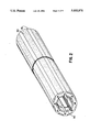
- FIG. 2 is a perspective view of a tubular extrusion in accordance with the present invention.
- FIG. 3 is an enlarged partial axial cross-section of a bearing in accordance with the present invention.
- FIG. 4 is a partial cross-section illustrating a bearing according to the present invention deflecting under the load of a rotating shaft.
- FIG. 5 is a diagram of the general steps employed in manufacturing a bearing according to the method of the present invention.
- FIG. 6 is an axial cross-section of another bearing in accordance with the present invention.
- FIG. 7 is an enlarged partial axial cross-section of the bearing of FIG. 6.
- FIG. 8 is a partial cross-section illustrating a bearing of FIG. 6 deflecting under the load of a rotating shaft.
- FIG. 9 is an axial cross-section of another bearing in accordance with the present invention.
- FIG. 10 is an axial cross-section of another bearing in accordance with the present invention.
- FIG. 1 is a cross-section of a typical extrudable bearing in accordance with the present invention.
- the bearing is considered extrudable because it has a constant axial cross-section as viewed in FIG. 1.
- the bearing has been machined to the precise required outer O.D. and inner diameter I.D.
- the phantom lines in FIG. 1 illustrate the inner and outer diameter after extrusion prior to machining.
- the bearing is placed in a housing which intimately contacts the outer diameter of the bearing and the bearing supports a shaft located within the inner diameter of the bearing.
- the outer diameter of the bearing is a function of the inner diameter of the housing into which the bearing is to be located and the inner diameter is a function of the size of the shaft to be supported.
- the inner diameter of the bearing is a predetermined amount larger than the outer diameter of the shaft which is to be supported by the bearing so as to allow a fluid film which supports the shaft.
- the bearing of the present invention is constructed entirely of non-newtonian fluidic materials preferably polymeric or elastomeric materials such as a rubber, plastic or the like.
- the bearing consists of a composite of sections of non-newtonian fluidic materials having different hardnesses.
- the bearing includes a unitary beam-like skeletal pad support portion 10 constructed of a relatively rigid or hard material, for example, hard durometer shore D rubber.
- the skeletal pad support portion 10 is generally circumferential in shape and includes a plurality of circumferentially spaced radially outwardly extending inner axial grooves 12 formed on the bearing's inner circumferential surface and circumferentially spaced radially inwardly extending outer axial grooves 14 formed on the bearing's outer surface. By virtue of these grooves, the skeletal pad support portion 10 of the illustrated bearing has a somewhat cogged discontinuous circumferential appearance.
- the particular shape of the bearing illustrated in FIG. 1 is by no means essential to the present invention and in fact is desirable for only specific applications.
- the specific cross-section of the bearing in accordance with the present invention for any particular application depends on the deflections required to achieve optimum results.
- the grooves could have various cross-sections, e.g., more or less tapered, to achieve the most desirable functions under load.
- the bearing could also be provided with at least one circumferentially extending undercut of the type shown at 12u.
- undercut per bearing pad is sufficient for a unidirectional bearing
- at least two symmetrically arranged undercuts per bearing pad should be provided if the bearing is to be bidirectional.
- FIG. 1 the single undercut and double undercut constructions are illustrated on one bearing pad each for simplicity. However, it should be understood that if either of these constructions is to be employed they must be used on each of the bearing pads to ensure uniform operation.
- FIG. 3 illustrates a portion of the beam network for a portion of a bearing similar to that shown in FIG. 1.
- the bearing shown in FIG. 1 includes eight bearing pad support sectors or segments. The pad support sectors or segments are defined by the spaced inner axial grooves 12.
- Each pad support sector or segment includes an arcuate bearing pad support face 16 defined by the radially innermost surface of the pad support segment, a housing contacting surface 18 defined by the radially outermost portions 18 of the pad support segments and a pair of connecting portions 20 connecting the housing contacting portions 18 with the bearing support face 16.
- the skeletal pad support portion 10 functions as a network of beams as illustrated in FIG. 3.
- the network of beams includes the inner circumferential beams illustrated at 26, the outer circumferential beams illustrated at 28 and the radial beams illustrated at 30. Under load, this network of bearing deflects in a manner which is determinable based upon the degree of the load, the material used in the skeletal pad support structure 10 and the size and spacing of the inner and outer axial grooves.
- the non-newtonian fluidic material used in the skeletal pad support portion 10 is described herein as relatively rigid or hard as compared to the relatively flexible or soft materials used in other portions of the bearings described below, the material used to form the skeletal pad support portion 10 is significantly more flexible than the metals which typically form the skeletal portions of journal or sleeve bearings. Accordingly, it is to be expected that the skeletal portion of the bearings of the present invention deflect under load to a far greater degree than bearings having metallic skeletal portions. A typical skeletal material in the present invention would have a hardness on the Shore D scale.
- the bearing of the present invention also includes a plurality of relatively soft or flexible bearing pads 50 corresponding in number to the number of bearing pad support surfaces provided on the skeletal portion 10.
- the bearing pads are preferably fused to the skeletal portion so as to be formed as part of the skeletal portion.
- the bearing pads 50 are concave in cross-section as shown in FIG. 1 and are somewhat radially thicker in the middle and arcuately taper inward toward their circumferential ends. The reason for this thicker middle and thinner end portion is to facilitate deflection of the bearing pad under load.
- the bearing pads 50 are formed of a relatively soft or flexible non-newtonian fluidic material, preferably a polymer or elastomer such as rubber, plastic or the like.
- the bearing pads 50 may be constructed of durometer Shore A rubber.
- the material used to form the bearing pad is preferably substantially softer or more flexible, i.e., less rigid, than the material used to form the skeletal portion 10. The softer material provides better performance and reduces shaft wear in low viscosity or abrasive lubricant operating conditions.
- both the skeletal portion 10 and the bearing pads 50 are constructed of non-newtonian fluids, they tend to flow in a determinable manner under load.
- the bearing is subject to both radial loads resulting from the weight of the shaft and shear loads resulting from the rotation of the shaft. Since the bearing is restrained in the radial direction by a housing in normal usage, the fluidic materials of which the bearing is constructed are incompressible in the radial direction. However, this is true only to the extent the bearing is restrained by the housing in the radial direction. For instance, if the outer axial grooves 14 are not filled, with deflection control members, as described below, portions along the outer circumference of the bearing are not restrained by the housing in the radial direction. Accordingly, some radial deflection of the bearing can occur.
- the bearing portions 50 deflect or flow to a much greater extent than the skeletal portion 10.
- the bearing pads 50 and the skeletal portion 10 deflect so as to form a wedge across the entire circumferential face of the bearing pads 50.
- the bearing of the present invention must be designed so as to deflect in a manner which allows formation of a hydrodynamic wedge across the entire innermost circumferential face of the bearing pads.
- Various factors must be taken into account to design a bearing to deflect in such a manner. For instance, the degree of shear and radial load applied, the flexibility of the materials employed in the bearing pad and skeletal portion, the size and shape of the inner and outer axial grooves and the flexibility of the bearing pads and skeletal portion all must be considered.
- the flexibility of the bearing pad and skeletal portion is ultimately a consequence of the design of the bearing.
- the flexibility of these elements can obviously be varied by varying the type of material employed in the bearing pads and skeletal portions.
- the flexibility is also influenced by the size, shape and circumferential positioning of the inner and outer axial grooves.
- the flexibility of the bearing pads and skeletal portions may also be influenced by providing non-newtonian fluidic material in all or part of either the outer or inner axial grooves.
- each of the outer axial grooves 14 are substantially completely filled by deflection control members 80.
- deflection control members 80 are provided only in the outer axial grooves, it is possible to provide deflection control members in the inner axial grooves as well. In any instance, the control members are preferably fused to either the skeletal portion and/or the bearing pad.
- the deflection control members 80 are of a relatively soft or flexible non-newtonian fluidic material preferably an elastomer or polymer such as rubber, plastic or the like.
- Shore A soft durometer rubber could be used to form the deflection control members as well as the bearing pads.
- different materials could be used depending upon the degree of deflection control required or desired.
- the deflection control members 80 have the same shape as the outer axial grooves 14. Accordingly, the deflection control members 80 fill the axial grooves 14 completely. However, this is not necessarily so. Specifically, it is possible that the deflection control members could be provided so as to only partially fill the grooves 14. This would of course, effect the degree of deflection control provided by the deflection control members.
- the deflection control members 80 act by filling the grooves to a predetermined extent so as to limit the flexibility in the shear direction of the skeletal portion 10. It follows that the degree of limiting of the flexibility of the skeletal portion depends upon the degree to which the deflection control members fill the inner and outer grooves and the flexibility of the material used in the deflection control members. It is also possible that the deflection control members could be constructed of the same material as the bearing pads and be formed to be unitary therewith. It is noted that with a filled groove the radial restraint is high while in the shear or circumferential direction the flexibility is high. In other words, the overall pad structure is stiff in the radial direction and flexible in the shear direction to form a wedge for hydrodynamic lubrication.
- the bearing of the present invention is preferably constructed entirely of new-newtonian fluidic materials preferably polymeric or elastomeric materials such as rubber, plastic and the like.
- the bearing of the present invention exhibits a number of unique performance characteristics. For instance, the high radial stiffness combined with the inward movement of the pad results in accurate shaft positioning and optimum fluid film formation. Film formation reduces shaft wear and provides for high load carrying capability. Additionally, bearings constructed of non-newtonian fluidic materials such as elastomers exhibit exceptional abrasion resistance in process lubricated applications.
- non-newtonian fluidic materials such as elastomers and polymers are also resistant to corrosion by substances which corrode non-fluidic materials such as metals.
- the need for radial stiffness and the need for abrasion resistance have heretofore been believed incompatible.
- the use of a multi-durometer composite consisting entirely of non-newtonian fluidic materials makes it possible to achieve both beneficial results.
- some non-newtonian fluidic materials such as elastomers and polymers are also resistant to corrosion by substances which corrode non-fluidic materials such as metals.
- the non-newtonian fluidic materials used in the bearings of the present invention are restrained along their outer periphery by the housing in which the bearing is located. Accordingly, the bearings are constrained to deflect or bulge along the axial end portions which are not restrained.
- the degree of bulging of the bearings out of the unrestrained axial ends thereof is indicative of the radial stiffness of the bearing.
- the degree of bulging, and hence the bearings radial stiffness depends on the size or area of unrestrained non-newtonian fluidic material and the stiffness of the non-newtonian fluidic material used.
- these wear-type bearings function mainly as elastomeric wear sleeves for the shaft.
- the resulting contact between the bearing pads and the shaft can generate a great deal of heat which can alter the material characteristics of the bearing pad material and thereby reduce the life expectancy of the bearing.
- the relatively stiff skeletal portion 10 is a large portion of the axial cross-section of the bearings of the present invention, the unrestrained cross-sectional area of the relatively soft durometer material in the bearings of the present invention is significantly reduced.
- the skeletal portion 10 is constructed of a relatively stiff material, it is not subject to a great deal of such bulging. Accordingly, only the materials used in the sections 80 and bearing pads 50 are subject to appreciable axial bulging. In other words, the cross-section bulge area of the bearings of the present invention is significantly reduced from that of prior art wear-type bearings.
- the provision of the relatively stiff skeletal portion provides the bearing with much greater radial stiffness.
- the bearing of the present invention does not simply deform, it also deflects to form a hydrodynamic wedge which allows the bearings of the present invention to carry a far greater load and, more importantly, reduces the wear on the bearings thereby increasing the life expectancy of the bearings.
- another significant advantage of the present invention is the reduction of bulging of the axial ends of the bearing which increases the radial stiffness of the bearing and reduces wear.
- FIGS. 1-4 the variations in rigidity are primarily provided through the use of materials having different rigidities. It is also possible to alter the rigidity of a bearing section by undercutting or otherwise altering its cross-sectional profile.
- FIGS. 6-10 illustrate embodiments of bearings in which variations in the rigidity of the pad support structure are introduced in whole, or in part, by alterations made to the cross-sectional profile.
- FIGS. 6-8 illustrate another extrudable bearing in accordance with the present invention. Again, the bearing is considered extrudable because it has a constant axial cross-section as viewed in FIG. 6.
- the bearing has been machined to the precise required outer diameter O.D. and inner diameter I.D.
- the phantom lines in FIG. 6 illustrate the inner and outer diameter after extrusion but prior to machining.
- the bearing is placed in a housing which intimately contacts the outer diameter of the bearing and the bearing supports a shaft located within the inner diameter of the bearing.
- the outer diameter of the bearing is a function of the inner diameter of the housing into which the bearing is to be located and inner diameter is the function of the size of the shaft to be supported.
- the inner diameter of the bearing is a predetermined amount larger than the outer diameter of the shaft which is to be supported by the bearing so as to allow fluid film which supports the shaft.
- FIGS. 6-8 utilizes the same principles described above with respect to the bearing shown in FIGS. 1-4.
- the variations in rigidity of the support structure required to achieve wedge formation are achieved both through the use of different materials and through the cross-sectional profile of the bearing.
- the bearing shown in FIG. 6 is constructed entirely of non-newtonian fluidic materials, preferably polymeric or elastomeric materials such as rubber, plastic, or the like.
- the bearing consists of a composite of non-newtonian fluidic materials having different hardnesses.
- the bearing includes a unitary beam-like skeletal pad support portion 110 constructed of a relatively rigid or hard material, for example, hard durometer shore D rubber.
- the skeletal pad support portion 110 is generally circumferential in shape and includes a plurality of circumferentially spaced radially outward extending inner axial grooves 112 which are flared to provide a plurality of circumferentially or tangentially extending grooves 112u extending from the outermost portion the inner axial grooves 112.
- the bearing of FIG. 6 also includes a plurality of relatively soft and flexible bearing pads 150 corresponding in number to the number of bearing pad support surfaces provided on the skeletal support portion 110.
- the bearing pads are preferably fused to the skeletal portion.
- the bearing pads 150 are concave in cross-section as shown in FIG.
- the bearing pads 150 are formed of a relatively soft or flexible non-newtonian fluidic material, preferably a polymer or elastomeric material such as rubber, plastic or the like.
- the bearing pads 150 may be constructed of Shore A durometer rubber.
- the material used to form the bearing pad is preferably substantially softer or more flexible than the material used to form the skeletal portion 110. The softer material can provide better performance and reduce shaft wear in low viscosity or abrasive lubricant operating conditions. However, as discussed below in connection with the embodiment of FIG. 9, it is not necessary to use bearing pads of a softer material.
- the tangential or circumferential grooves 112u undercut either the bearing pads (in the case of an I-shaped pad support portion) or the bearing pad support portion (in the case of a T-shaped pad support portion).
- the tangential or circumferentially extending axial grooves 112u undercut the plurality of bearing pads 150 defined by the axial grooves 112.
- the axial grooves 112 and the tangential or circumferential grooves 112u together define a skeletal pad support portion 110 which has the appearance of a continuous ring having a plurality of equally spaced pedestals extending radially inward.
- the pedestals of the skeletal support portion 110 may be either T-shaped or I-shaped, the difference being the circumferential extent of the pad support surface. More specifically, the support face may extend along the entire bearing pad or only a circumferential portion thereof as shown, depending on the size and location of the undercut 112u.
- the skeletal support portion 110 could be provided with a plurality of spaced outer axial grooves such as those shown at 14 in FIG. 1. Further, many of the grooves provided in the skeletal support portion could have various cross-sections, e.g., more or less tapered, to achieve the desired function under load.
- a cantilever-type support for the bearing pads 150 by defining a pad support portion which is capable of deflection in the circumferential direction relatively easily.
- the skeletal support portion forms a radially rigid pad support portion such that the bearing is not too easily compressed in the radial direction.
- bearings shown in FIGS. 6-8 may be extruded into long tubes in the manner shown in FIG. 2.
- FIG. 6 When the bearing illustrated in FIG. 6 is provided with inner axial grooves and tangential or circumferential grooves as illustrated in FIG. 6, the skeletal pads support portions functions as a network of beams adapted to deflect under load.
- FIG. 7 illustrates a portion of the beam network for a portion of a bearing similar to that shown in FIG. 6.
- the bearing shown in FIG. 6 includes eight pad support sectors or segments. As noted above, the pad support sectors or segments are defined by the spaced inner axial grooves 112 and the tangential or circumferential grooves 112u which can either undercut the pad support segment or reduce its circumferential face width.
- Each pad support sector includes an arcuate bearing pad support face 116 defined by the radially innermost surface of the pad support segment, a pedestal-like connecting portion 120 and a housing contacting surface 118 supporting the pedestal portion.
- the skeletal pad support portion 110 functions as a network of beams as illustrated in FIG. 7.
- the network of beams includes a circumferential beam 126 defined by either the pad support surface or the bearing pad itself, a radially extending pedestal type beam 130 and tangential or circumferential outer beams 128. Under load this network of beams deflects in a manner which is determinable based upon the degree of load, the material used in the skeletal pad support structure 110, and the size and spacing of the grooves 112 and 112u.
- both the skeletal portion 110 and the bearing pads 150 are constructed of non-newtonian fluids, they tend to flow in a determinable manner under load.
- the bearing is subject to both radial loads resulting from the weight of the shaft and shear loads resulting from the rotation of the shaft. Since the bearing is restrained in the radial direction by housing in normal usage, the fluidic materials of which the bearing is constructed are nearly incompressible in the radial direction. However, this is true only to the extent the bearing is restrained by the housing in the radial direction. Thus, those portions of the bearing pad or bearing pad's support surface which are undercut are not restrained by the housing in the radial direction. Accordingly, these portions are subject to radial deflection which can result in flow of the non-newtonian fluidic material.
- the entire bearing pad 150 and the associated segment of the skeletal portion 110 can swing upward in response to the shear load applied by the rotating shaft to form a hydrodynamic wedge.
- An example of such deflection is illustrated in FIG. 8.
- the bearing pads 150 and the skeletal portion 110 deflects so to form a wedge across the entire circumferential face of the bearing pads 150.
- FIGS. 9 and 10 illustrate bearings in which variations in the rigidity of the support structure and the advantageous results of the present invention are achieved simply by constructing the bearing of a relatively rigid non-newtonian fluid and providing inner grooves 212 with undercuts 212u.
- the provision of axial grooves 212 and undercuts 212u results in a variation in the rigidity of the support structure. This, taken in conjunction with the use of non-newtonian fluidic materials allows wedge formation under loading.
- the provision of the inner axial grooves 212 and the undercut extensions 212u thereof define a pedestal-type support structure for the bearing pads. Because the bearing has a homogeneous construction the pad material flows at the same rate as the support structure under load.
- a bearing such as that shown in FIG. 10 offers the advantage of having a smaller radial envelope than conventional bearings or the bearing shown in FIG. 9. This is an advantage both because it reduces the size of the housing necessary to support the bearing and because it allows the use of proportionately smaller bearings in applications requiring them.
- the non-newtonian fluidic material used in the skeletal pad support portion 10, 110, 210 is described as relatively rigid or hard as compared to a relatively flexible or soft material used in other portions of the bearings described above, the material used to form the skeletal pad support portion 10, 110, 210 is significantly more flexible than the metals which typically form the skeletal portions of journal or sleeve bearings. Accordingly, it is to be expected that the skeletal portion of the bearings of the present invention deflect under load to a far greater extent than bearings having a metallic skeletal portion. A typical skeletal material in the present invention would have a hardness on the Shore D scale.
- the bearing of the present invention includes a generally circumferential skeletal portion formed of a relatively rigid non-newtonian fluid.
- a plurality of inner axially extending radial grooves are formed on the inner circumference of the skeletal portion.
- the inner axial grooves are circumferentially spaced with respect to one another.
- the inner axial grooves may be circumferentially flared or extended to undercut the bearing pads.
- the skeletal portion also can include a plurality of outer axial grooves preferably equal in number to the inner axial grooves and spaced about the outer circumference of the skeletal portion preferably centered about a mid point which is directly between two opposed inner axial grooves.
- the bearing further includes a plurality of bearing pads equal in number to the inner axial grooves.
- the bearing pads can be integral with the skeletal structure or they can be separate and fused to portions of the skeletal portion defined by the inner axial grooves so as to be formed as an integral part thereof.
- the bearing may also include deflection control members located in the inner axial grooves and/or the outer axial grooves. The deflection control members may fill entirely the axial grooves or only partially fill the axial grooves.
- the bearing pad support can be designed for movement with six degrees of freedom.
- the bearing pad support of conventional wear-type bearings cannot move in the radial direction.
- the tendency of the bearing pads to deflect and the degree of deflection under a known load may be varied by varying a number of different parameters.
- the degree of deflection can be varied by varying the cross-section of the bearing. Specifically, the number and depth of the inner and outer axial grooves and the circumferential dimensions of the bearing pads and skeletal portion define the beam network for supporting the bearing pads and consequently influence the degree of deflection of the bearing pads under load.
- the choice of materials for the various components of the bearing affects the deflection characteristics of the bearing.
- the hardness or flexibility of the non-newtonian fluidic material employed is the most critical characteristic to be taken into consideration.
- the size and location of the deflection control members influences the deflection characteristics of the bearing.
- the deflection control member can be constructed of the same material as the skeletal portion so that, for practical purposes, the skeletal portion does not include the outer axial grooves.
- the outer axial grooves or the inner axial grooves can be left completely unfilled to allow free, unrestrained deflection.
- the bearings of the present invention When provided with a composite construction, the bearings of the present invention also may be generally characterized as a multi-durometer bearings since they include multiple sections having different durometers (degrees of rigidity). Specifically, higher durometer (more rigid) non-newtonian fluids are used for strength and low durometer (more flexible) non-newtonian fluidic materials are used for flexibility.
- the various durometer sections are fused together. For instance, in the bearing illustrated in FIGS. 1-4 different materials could be used for the skeletal portion, the bearing pads and the deflection control members. Generally, more rigid materials would be used for the skeletal portion and less rigid, more flexible, materials would be used for the bearing pads and the deflection control members.
- novel bearing of the present invention may be made in accordance with a novel method of manufacture which is discussed hereinafter with reference to FIG. 5.
- the method of making a bearing in accordance with the present invention involves four general steps, to wit, extrusion, curing, cutting and sizing.
- the first step, extrusion can involve two or more sub-steps.
- the number of sub-steps depends upon the number of different materials to be used in the bearing and the location of the various bearing sections. It should be pointed out that the multidurometer form of bearing is extruded using known multidurometer extrusion techniques which are commonly employed in extruding plastic components such as window and door seals, shock absorbing bumpers, and flexible hinges. In the example illustrated in FIG. 5, three extrusion sub-steps are employed. This corresponds to the number of extrusion sub-steps which would be preferably be used to form a bearing of the type shown in FIG. 1.
- a first portion of the bearing is extruded.
- the first portion to be extruded would presumably be the inner portion 50. This portion would be extruded in an uncured or partially cured state.
- the entire bearing is extruded in one step.
- Step 102 closely follows step 101 and involves the extrusion of a second portion onto the uncured or partially cured first portion. In extruding the bearing illustrated in FIG. 1, step 102, would presumably involve the extrusion of the skeletal portion 10 onto the associated portion of the pad face 50.
- step 102 After completion of step 102, if additional bearing sections are required, they are extruded in further extrusion sub-steps.
- a third extrusion sub-step 103 is performed. During this extrusion sub-step the outer deflection control members 80 are extruded into the outer axial grooves.
- each successive extrusion is uncured or only partially cured so that it is not necessary to apply an adhesive to join the successive extrusions during the extrusion process.
- the non-newtonian fluidic materials employed in the bearings of the present invention are gummy or tacky such that no adhesive is necessary to adhere the successive excretion extrusions.
- the bearing sections are fused to one another without the aid of a foreign substance such as an adhesive.
- Completion of the extrusion process yields a composite uncured or partially cured tubular extrusion.
- the composite tubular extrusion is cured at step 104 to yield a cured tubular extrusion in which the various bearing sections having varied durometers are fused to one another.
- FIG. 2 illustrates an example of a tubular extrusion in accordance with the present invention.
- the extrusion is preferably quite long so that a large number of bearings can be formed from any one extrusion.
- the cured tubular extrusion is cut into segments having axial thicknesses corresponding to the desired axial thickness of the bearing.
- a tubular extrusion is divided into bearing segments.
- one tubular extrusion, such as that shown in FIG. 1, may be divided into 40-50 individual bearing segments.
- the individual bearing segments are sized.
- the sizing step simply involves machining the bearing segments to define precisely the desired inner and outer diameters. Naturally, this step is only possible if the tubular extrusion has a outer diameter which is larger than the desired outer diameter and an inner diameter which is smaller than the desired inner diameter.
- the phantom lines illustrate generally, the degree of extra material which should be provided to insure that the bearing segments can be properly sized.
- the sizing step 106 can also involve additional machining of the bearing segments to the extent cost of such machining is justified by the improved performance derived from the additional machining. For instance, it may also be desirable to provide non-uniformities in the cross-section of the bearing segments such as circumferential grooves and radial bores. Such steps, which can potentially add a great deal to the cost of individual bearings, would normally not be justified, particularly since a wide variety of deflection characteristics can be achieved, as discussed above, while maintaining a constant extrudable bearing cross-section.
Abstract
Description
Claims (35)
Priority Applications (1)
| Application Number | Priority Date | Filing Date | Title |
|---|---|---|---|
| US07/544,933 US5033871A (en) | 1988-10-25 | 1990-06-28 | Extrudable multi-rigidity hydrodynamic bearing and method of making the same |
Applications Claiming Priority (2)
| Application Number | Priority Date | Filing Date | Title |
|---|---|---|---|
| US26235288A | 1988-10-25 | 1988-10-25 | |
| US07/544,933 US5033871A (en) | 1988-10-25 | 1990-06-28 | Extrudable multi-rigidity hydrodynamic bearing and method of making the same |
Related Parent Applications (1)
| Application Number | Title | Priority Date | Filing Date |
|---|---|---|---|
| US26235288A Continuation-In-Part | 1988-10-25 | 1988-10-25 |
Publications (1)
| Publication Number | Publication Date |
|---|---|
| US5033871A true US5033871A (en) | 1991-07-23 |
Family
ID=26949166
Family Applications (1)
| Application Number | Title | Priority Date | Filing Date |
|---|---|---|---|
| US07/544,933 Expired - Fee Related US5033871A (en) | 1988-10-25 | 1990-06-28 | Extrudable multi-rigidity hydrodynamic bearing and method of making the same |
Country Status (1)
| Country | Link |
|---|---|
| US (1) | US5033871A (en) |
Cited By (22)
| Publication number | Priority date | Publication date | Assignee | Title |
|---|---|---|---|---|
| US5455778A (en) * | 1987-05-29 | 1995-10-03 | Ide; Russell D. | Bearing design analysis apparatus and method |
| DE19627288A1 (en) * | 1995-07-10 | 1997-01-16 | Leica Inc | Axial bearing for high precision machinery - has outer sleeve with inwardly projecting arms that grasp shaft to allow its relative radial and axial movement |
| US5752318A (en) * | 1995-12-06 | 1998-05-19 | Ingersoll-Rand Company | Hydrodynamic bearing and method |
| US5938344A (en) * | 1997-03-26 | 1999-08-17 | Sabin; Jeffrey M. | Temperature compensating bearing |
| US6238093B1 (en) * | 1997-04-17 | 2001-05-29 | Duramax Marine, Llc | Partial arc bearing assembly and method of making the same |
| US20030174918A1 (en) * | 2001-06-11 | 2003-09-18 | Tribotek, Inc. | Contact bearing |
| US6648510B2 (en) | 2000-08-24 | 2003-11-18 | Duramax Marine, Llc | SPA super demountable bearing |
| US6702502B1 (en) * | 1999-08-13 | 2004-03-09 | ZF Lemförder Metallwaren AG | Ball-and-socket joint |
| US20060147139A1 (en) * | 2005-01-06 | 2006-07-06 | Snecma | Member for the guidance of a movable piece |
| US20060278439A1 (en) * | 2005-06-09 | 2006-12-14 | Ide Russell D | Thrust bearing assembly |
| US20070183700A1 (en) * | 2006-02-06 | 2007-08-09 | Olaf Winterhalter | Fluid dynamic bearing system |
| US20080159671A1 (en) * | 2006-08-02 | 2008-07-03 | Miba Gleitlager Gmbh | Anti-Friction Layer for a Bearing Element |
| US20090229504A1 (en) * | 2008-03-17 | 2009-09-17 | Hiroshi Iwakami | Steering unit for small watercraft |
| US20090268995A1 (en) * | 2005-06-09 | 2009-10-29 | Ceradyne, Inc. | Thrust bearing assembly |
| US20100199800A1 (en) * | 2009-02-09 | 2010-08-12 | Denso Corporation | Spring damper and acceleration device using the same |
| US20100273590A1 (en) * | 2009-04-28 | 2010-10-28 | Schaeffler Technologies Gmbh & Co. Kg | Timing chain pivoting guide having a rubber spring element |
| US20160138652A1 (en) * | 2014-11-14 | 2016-05-19 | Saint-Gobain Performance Plastics Corporation | Device and method of anchoring a polymer to a substrate |
| US20160237835A1 (en) * | 2013-10-11 | 2016-08-18 | United Technologies Corporation | Compressible fan blade with root spacer |
| US9863191B1 (en) | 2014-05-02 | 2018-01-09 | Russell D. Ide | Flexible coupling |
| US10294986B2 (en) * | 2015-08-25 | 2019-05-21 | Us Synthetic Corporation | Tilting pad bearing assemblies; bearing apparatuses and methods of using the same |
| US11428264B2 (en) | 2016-10-31 | 2022-08-30 | Fischer Engineering Solutions Ag | Rotary system with axial gas bearing |
| US20230258229A1 (en) * | 2019-12-10 | 2023-08-17 | Ingersoll-Rand Industrial U.S., Inc. | Flex pad bearing pad configuration |
Citations (53)
| Publication number | Priority date | Publication date | Assignee | Title |
|---|---|---|---|---|
| US1991461A (en) * | 1932-10-10 | 1935-02-19 | Kingsbury Machine Works Inc | Bearing |
| US2424028A (en) * | 1943-07-01 | 1947-07-15 | Worthington Pump & Mach Corp | Bearing |
| FR1010959A (en) * | 1948-11-12 | 1952-06-17 | Neyrpic Ets | Improvements to pivoting of rotating machines |
| DE879116C (en) * | 1950-07-16 | 1953-06-11 | Josef Haas | Train protection system for rail vehicles, preferably for railways |
| US2778696A (en) * | 1955-01-12 | 1957-01-22 | Ralph D Lease | Thrust bearing structure |
| US2890916A (en) * | 1956-04-02 | 1959-06-16 | Smith Corp A O | Thrust bearing |
| US2906571A (en) * | 1954-04-10 | 1959-09-29 | Neypric Ets | Thrust bearing construction for rotatable spindles and the like |
| US3062598A (en) * | 1959-04-23 | 1962-11-06 | Gen Electric | Thrust bearing |
| US3107955A (en) * | 1961-02-13 | 1963-10-22 | Dresser Ind | Bearing |
| US3424505A (en) * | 1966-10-10 | 1969-01-28 | Eastern Bearings & Mfg Co Inc | Fluid bearing |
| US3675977A (en) * | 1969-10-09 | 1972-07-11 | Skf Ind Trading & Dev | Bearing for supporting heavy rotating machinery |
| US3687506A (en) * | 1970-03-09 | 1972-08-29 | Colin William Dee | Fluid pad bearing |
| US3791703A (en) * | 1970-11-30 | 1974-02-12 | Ifield Lab Pty Ltd | Journal support bearings for rotating shafts |
| US3829180A (en) * | 1973-04-16 | 1974-08-13 | Waukesha Bearings Corp | Pad construction for tilting pad thrust bearing |
| GB1370522A (en) * | 1971-03-16 | 1974-10-16 | Laing Nikolaus | Plain bearings |
| US3881791A (en) * | 1973-03-02 | 1975-05-06 | Skf Ind Trading & Dev | Dry journal bearing |
| US3899224A (en) * | 1973-03-30 | 1975-08-12 | Nasa | Lubricated journal bearing |
| US3902770A (en) * | 1973-04-18 | 1975-09-02 | Dornier System Gmbh | Hydrodynamically-acting friction bearing and method of manufacture |
| US3902771A (en) * | 1974-03-26 | 1975-09-02 | Us Navy | Rubber stave bearing which will permit slow speed motion without stick-slip and resultant squeal |
| US3913989A (en) * | 1972-02-11 | 1975-10-21 | Atomic Energy Authority Uk | Air bearings |
| US3930691A (en) * | 1974-04-12 | 1976-01-06 | Jerome Greene | Swing pad bearing |
| US3944304A (en) * | 1973-10-11 | 1976-03-16 | Sulzer Brothers Limited | Gas-lubricated self-pressurizing radial bearing |
| US3951475A (en) * | 1973-04-24 | 1976-04-20 | Toyota Jidosha Kogyo Kabushiki Kaisha | Resiliently mounted gas bearing device |
| US3954309A (en) * | 1974-11-21 | 1976-05-04 | The Hutson Corporation | Hydrodynamic bearings for vibratory mechanisms |
| US3971606A (en) * | 1974-01-18 | 1976-07-27 | Ishikawajima-Harima Jukogyo Kabushiki Kaisha | Water lubricated bearing device |
| GB1458047A (en) * | 1973-11-20 | 1976-12-08 | Atomic Energy Authority Uk | Bearings and journal assemblies process for preparing aryl-substituted pyridones |
| US4118079A (en) * | 1976-06-12 | 1978-10-03 | Rolls-Royce Limited | Fluid bearings with conforming shells |
| US4133585A (en) * | 1977-08-04 | 1979-01-09 | United Technologies Corporation | Resilient foil journal bearing |
| US4178046A (en) * | 1976-05-24 | 1979-12-11 | The Garrett Corporation | Foil bearing |
| US4227752A (en) * | 1978-12-29 | 1980-10-14 | Mechanical Technology Incorporated | Staged bearing surface compliance for hydrodynamic fluid bearing |
| US4243274A (en) * | 1978-08-28 | 1981-01-06 | Jerome Greene | Hydrodynamic bearing with radial, thrust and moment load capacity |
| US4268094A (en) * | 1977-01-06 | 1981-05-19 | Jerome Greene | Radial and thrust-type hydrodynamic bearing capable of accommodating misalignment |
| US4277113A (en) * | 1979-10-01 | 1981-07-07 | Mechanical Technology Incorporated | Composite material compliant bearing element |
| US4290656A (en) * | 1979-10-26 | 1981-09-22 | The United States Of America As Represented By The Secretary Of The Navy | Hydrodynamic bearing with extended pressure gradient |
| US4319790A (en) * | 1977-07-07 | 1982-03-16 | Thomson George A | Water lubricated sleeve bearings |
| US4325585A (en) * | 1979-10-18 | 1982-04-20 | Toyoda Koki Kabushiki Kaisha | Fluid bearing |
| US4382199A (en) * | 1980-11-06 | 1983-05-03 | Nu-Tech Industries, Inc. | Hydrodynamic bearing system for a brushless DC motor |
| US4403873A (en) * | 1982-01-11 | 1983-09-13 | Waukesha Bearings Corporation | Tilting pad thrust bearing |
| US4435839A (en) * | 1982-09-21 | 1984-03-06 | The Garrett Corporation | Foil bearing rubbing surface coating application methods |
| US4459047A (en) * | 1979-04-27 | 1984-07-10 | The Garrett Corporation | Foil bearing surfaces and method of making same |
| US4496251A (en) * | 1984-05-14 | 1985-01-29 | Ide Russell D | Pad-type hydrodynamic bearing |
| US4515486A (en) * | 1984-02-03 | 1985-05-07 | Ide Russell D | Elastomeric supported hydrodynamic bearing |
| US4526482A (en) * | 1984-02-07 | 1985-07-02 | Ide Russell D | Hydrodynamic bearing surface for high loads and low viscosity lubricating fluids |
| US4531846A (en) * | 1983-12-27 | 1985-07-30 | Ferrofluidics Corporation | Compact ferrofluid seal and bearing assembly |
| US4560014A (en) * | 1982-04-05 | 1985-12-24 | Smith International, Inc. | Thrust bearing assembly for a downhole drill motor |
| US4583870A (en) * | 1983-09-29 | 1986-04-22 | Schnittger Jan R | Hydrodynamic bearing unit |
| EP0206686A2 (en) * | 1985-06-17 | 1986-12-30 | IDE, Russell Douglas | Multi-deflection pad-type hydrodynamic bearing |
| US4639146A (en) * | 1983-04-15 | 1987-01-27 | Hitachi, Ltd. | Thrust bearing |
| US4647227A (en) * | 1985-01-28 | 1987-03-03 | Societe Anonyme: Societe Europeenne De Propulsion | Bearing, such as for rotary shaft |
| US4654939A (en) * | 1979-04-27 | 1987-04-07 | The Garrett Corporation | Foil bearing surfaces and method of making same |
| US4676668A (en) * | 1985-06-17 | 1987-06-30 | Ide Russell D | Multi-deflection pad-type hydrodynamic bearing |
| US4725151A (en) * | 1986-07-25 | 1988-02-16 | The B. F. Goodrich Company | Thermoplastic-rubber polymer alloys and method of producing the same |
| US4738453A (en) * | 1987-08-17 | 1988-04-19 | Ide Russell D | Hydrodynamic face seal with lift pads |
-
1990
- 1990-06-28 US US07/544,933 patent/US5033871A/en not_active Expired - Fee Related
Patent Citations (53)
| Publication number | Priority date | Publication date | Assignee | Title |
|---|---|---|---|---|
| US1991461A (en) * | 1932-10-10 | 1935-02-19 | Kingsbury Machine Works Inc | Bearing |
| US2424028A (en) * | 1943-07-01 | 1947-07-15 | Worthington Pump & Mach Corp | Bearing |
| FR1010959A (en) * | 1948-11-12 | 1952-06-17 | Neyrpic Ets | Improvements to pivoting of rotating machines |
| DE879116C (en) * | 1950-07-16 | 1953-06-11 | Josef Haas | Train protection system for rail vehicles, preferably for railways |
| US2906571A (en) * | 1954-04-10 | 1959-09-29 | Neypric Ets | Thrust bearing construction for rotatable spindles and the like |
| US2778696A (en) * | 1955-01-12 | 1957-01-22 | Ralph D Lease | Thrust bearing structure |
| US2890916A (en) * | 1956-04-02 | 1959-06-16 | Smith Corp A O | Thrust bearing |
| US3062598A (en) * | 1959-04-23 | 1962-11-06 | Gen Electric | Thrust bearing |
| US3107955A (en) * | 1961-02-13 | 1963-10-22 | Dresser Ind | Bearing |
| US3424505A (en) * | 1966-10-10 | 1969-01-28 | Eastern Bearings & Mfg Co Inc | Fluid bearing |
| US3675977A (en) * | 1969-10-09 | 1972-07-11 | Skf Ind Trading & Dev | Bearing for supporting heavy rotating machinery |
| US3687506A (en) * | 1970-03-09 | 1972-08-29 | Colin William Dee | Fluid pad bearing |
| US3791703A (en) * | 1970-11-30 | 1974-02-12 | Ifield Lab Pty Ltd | Journal support bearings for rotating shafts |
| GB1370522A (en) * | 1971-03-16 | 1974-10-16 | Laing Nikolaus | Plain bearings |
| US3913989A (en) * | 1972-02-11 | 1975-10-21 | Atomic Energy Authority Uk | Air bearings |
| US3881791A (en) * | 1973-03-02 | 1975-05-06 | Skf Ind Trading & Dev | Dry journal bearing |
| US3899224A (en) * | 1973-03-30 | 1975-08-12 | Nasa | Lubricated journal bearing |
| US3829180A (en) * | 1973-04-16 | 1974-08-13 | Waukesha Bearings Corp | Pad construction for tilting pad thrust bearing |
| US3902770A (en) * | 1973-04-18 | 1975-09-02 | Dornier System Gmbh | Hydrodynamically-acting friction bearing and method of manufacture |
| US3951475A (en) * | 1973-04-24 | 1976-04-20 | Toyota Jidosha Kogyo Kabushiki Kaisha | Resiliently mounted gas bearing device |
| US3944304A (en) * | 1973-10-11 | 1976-03-16 | Sulzer Brothers Limited | Gas-lubricated self-pressurizing radial bearing |
| GB1458047A (en) * | 1973-11-20 | 1976-12-08 | Atomic Energy Authority Uk | Bearings and journal assemblies process for preparing aryl-substituted pyridones |
| US3971606A (en) * | 1974-01-18 | 1976-07-27 | Ishikawajima-Harima Jukogyo Kabushiki Kaisha | Water lubricated bearing device |
| US3902771A (en) * | 1974-03-26 | 1975-09-02 | Us Navy | Rubber stave bearing which will permit slow speed motion without stick-slip and resultant squeal |
| US3930691A (en) * | 1974-04-12 | 1976-01-06 | Jerome Greene | Swing pad bearing |
| US3954309A (en) * | 1974-11-21 | 1976-05-04 | The Hutson Corporation | Hydrodynamic bearings for vibratory mechanisms |
| US4178046A (en) * | 1976-05-24 | 1979-12-11 | The Garrett Corporation | Foil bearing |
| US4118079A (en) * | 1976-06-12 | 1978-10-03 | Rolls-Royce Limited | Fluid bearings with conforming shells |
| US4268094A (en) * | 1977-01-06 | 1981-05-19 | Jerome Greene | Radial and thrust-type hydrodynamic bearing capable of accommodating misalignment |
| US4319790A (en) * | 1977-07-07 | 1982-03-16 | Thomson George A | Water lubricated sleeve bearings |
| US4133585A (en) * | 1977-08-04 | 1979-01-09 | United Technologies Corporation | Resilient foil journal bearing |
| US4243274A (en) * | 1978-08-28 | 1981-01-06 | Jerome Greene | Hydrodynamic bearing with radial, thrust and moment load capacity |
| US4227752A (en) * | 1978-12-29 | 1980-10-14 | Mechanical Technology Incorporated | Staged bearing surface compliance for hydrodynamic fluid bearing |
| US4459047A (en) * | 1979-04-27 | 1984-07-10 | The Garrett Corporation | Foil bearing surfaces and method of making same |
| US4654939A (en) * | 1979-04-27 | 1987-04-07 | The Garrett Corporation | Foil bearing surfaces and method of making same |
| US4277113A (en) * | 1979-10-01 | 1981-07-07 | Mechanical Technology Incorporated | Composite material compliant bearing element |
| US4325585A (en) * | 1979-10-18 | 1982-04-20 | Toyoda Koki Kabushiki Kaisha | Fluid bearing |
| US4290656A (en) * | 1979-10-26 | 1981-09-22 | The United States Of America As Represented By The Secretary Of The Navy | Hydrodynamic bearing with extended pressure gradient |
| US4382199A (en) * | 1980-11-06 | 1983-05-03 | Nu-Tech Industries, Inc. | Hydrodynamic bearing system for a brushless DC motor |
| US4403873A (en) * | 1982-01-11 | 1983-09-13 | Waukesha Bearings Corporation | Tilting pad thrust bearing |
| US4560014A (en) * | 1982-04-05 | 1985-12-24 | Smith International, Inc. | Thrust bearing assembly for a downhole drill motor |
| US4435839A (en) * | 1982-09-21 | 1984-03-06 | The Garrett Corporation | Foil bearing rubbing surface coating application methods |
| US4639146A (en) * | 1983-04-15 | 1987-01-27 | Hitachi, Ltd. | Thrust bearing |
| US4583870A (en) * | 1983-09-29 | 1986-04-22 | Schnittger Jan R | Hydrodynamic bearing unit |
| US4531846A (en) * | 1983-12-27 | 1985-07-30 | Ferrofluidics Corporation | Compact ferrofluid seal and bearing assembly |
| US4515486A (en) * | 1984-02-03 | 1985-05-07 | Ide Russell D | Elastomeric supported hydrodynamic bearing |
| US4526482A (en) * | 1984-02-07 | 1985-07-02 | Ide Russell D | Hydrodynamic bearing surface for high loads and low viscosity lubricating fluids |
| US4496251A (en) * | 1984-05-14 | 1985-01-29 | Ide Russell D | Pad-type hydrodynamic bearing |
| US4647227A (en) * | 1985-01-28 | 1987-03-03 | Societe Anonyme: Societe Europeenne De Propulsion | Bearing, such as for rotary shaft |
| EP0206686A2 (en) * | 1985-06-17 | 1986-12-30 | IDE, Russell Douglas | Multi-deflection pad-type hydrodynamic bearing |
| US4676668A (en) * | 1985-06-17 | 1987-06-30 | Ide Russell D | Multi-deflection pad-type hydrodynamic bearing |
| US4725151A (en) * | 1986-07-25 | 1988-02-16 | The B. F. Goodrich Company | Thermoplastic-rubber polymer alloys and method of producing the same |
| US4738453A (en) * | 1987-08-17 | 1988-04-19 | Ide Russell D | Hydrodynamic face seal with lift pads |
Non-Patent Citations (4)
| Title |
|---|
| B. F. Goodrich, Cutless Bearings for Propeller Shafts and Rudders, Bulletin No. 482 F, pp. 1 6 (1957). * |
| B. F. Goodrich, Cutless Bearings for Propeller Shafts and Rudders, Bulletin No. 482-F, pp. 1-6 (1957). |
| Carlisle Geauga Co., Your Single Source for Custom Rubber & Plastic Products Brochure, pp. 1 15 (no date). * |
| Carlisle Geauga Co., Your Single Source for Custom Rubber & Plastic Products Brochure, pp. 1-15 (no date). |
Cited By (40)
| Publication number | Priority date | Publication date | Assignee | Title |
|---|---|---|---|---|
| US5455778A (en) * | 1987-05-29 | 1995-10-03 | Ide; Russell D. | Bearing design analysis apparatus and method |
| DE19627288A1 (en) * | 1995-07-10 | 1997-01-16 | Leica Inc | Axial bearing for high precision machinery - has outer sleeve with inwardly projecting arms that grasp shaft to allow its relative radial and axial movement |
| US5752318A (en) * | 1995-12-06 | 1998-05-19 | Ingersoll-Rand Company | Hydrodynamic bearing and method |
| US6406184B2 (en) * | 1996-04-18 | 2002-06-18 | Duramax Marine, Llc | Partial arc bearing slab |
| US5938344A (en) * | 1997-03-26 | 1999-08-17 | Sabin; Jeffrey M. | Temperature compensating bearing |
| US6238093B1 (en) * | 1997-04-17 | 2001-05-29 | Duramax Marine, Llc | Partial arc bearing assembly and method of making the same |
| US6702502B1 (en) * | 1999-08-13 | 2004-03-09 | ZF Lemförder Metallwaren AG | Ball-and-socket joint |
| US6648510B2 (en) | 2000-08-24 | 2003-11-18 | Duramax Marine, Llc | SPA super demountable bearing |
| US20030174918A1 (en) * | 2001-06-11 | 2003-09-18 | Tribotek, Inc. | Contact bearing |
| US7077573B2 (en) | 2001-06-11 | 2006-07-18 | Tribotek, Inc. | Contact bearing |
| US7695194B2 (en) * | 2005-01-06 | 2010-04-13 | Snecma | Member for the guidance of a movable piece |
| US20060147139A1 (en) * | 2005-01-06 | 2006-07-06 | Snecma | Member for the guidance of a movable piece |
| US20100187014A1 (en) * | 2005-06-09 | 2010-07-29 | Ceradyne, Inc. | Thrust Bearing Assembly |
| US7306059B2 (en) | 2005-06-09 | 2007-12-11 | Russell Douglas Ide | Thrust bearing assembly |
| US20090268995A1 (en) * | 2005-06-09 | 2009-10-29 | Ceradyne, Inc. | Thrust bearing assembly |
| US20060278439A1 (en) * | 2005-06-09 | 2006-12-14 | Ide Russell D | Thrust bearing assembly |
| US8016052B2 (en) | 2005-06-09 | 2011-09-13 | Ceradyne, Inc. | Thrust bearing assembly |
| US8118117B2 (en) | 2005-06-09 | 2012-02-21 | Ceradyne, Inc. | Thrust bearing assembly |
| US20070183700A1 (en) * | 2006-02-06 | 2007-08-09 | Olaf Winterhalter | Fluid dynamic bearing system |
| US20080159671A1 (en) * | 2006-08-02 | 2008-07-03 | Miba Gleitlager Gmbh | Anti-Friction Layer for a Bearing Element |
| US7942581B2 (en) * | 2006-08-02 | 2011-05-17 | Miba Gleitlager Gmbh | Anti-friction layer for a bearing element |
| US20090229504A1 (en) * | 2008-03-17 | 2009-09-17 | Hiroshi Iwakami | Steering unit for small watercraft |
| US8042481B2 (en) * | 2008-03-17 | 2011-10-25 | Honda Motor Co., Ltd. | Steering unit for small watercraft |
| US8646356B2 (en) * | 2009-02-09 | 2014-02-11 | Denso Corporation | Spring damper and acceleration device using the same |
| US20100199800A1 (en) * | 2009-02-09 | 2010-08-12 | Denso Corporation | Spring damper and acceleration device using the same |
| US20100273590A1 (en) * | 2009-04-28 | 2010-10-28 | Schaeffler Technologies Gmbh & Co. Kg | Timing chain pivoting guide having a rubber spring element |
| US8308588B2 (en) * | 2009-04-28 | 2012-11-13 | Schaeffler Technologies AG & Co. KG | Timing chain pivoting guide having a rubber spring element |
| US10280771B2 (en) * | 2013-10-11 | 2019-05-07 | United Technologies Corporation | Compressible fan blade with root spacer |
| US20160237835A1 (en) * | 2013-10-11 | 2016-08-18 | United Technologies Corporation | Compressible fan blade with root spacer |
| US10753159B1 (en) | 2014-05-02 | 2020-08-25 | Russell D. Ide | Flexible coupling |
| US9863191B1 (en) | 2014-05-02 | 2018-01-09 | Russell D. Ide | Flexible coupling |
| US10435954B1 (en) | 2014-05-02 | 2019-10-08 | Russell D. Ide | Flexible coupling |
| KR20170074984A (en) * | 2014-11-14 | 2017-06-30 | 생-고뱅 퍼포먼스 플라스틱스 코포레이션 | Device and method of anchoring a polymer to a substrate |
| US10240634B2 (en) * | 2014-11-14 | 2019-03-26 | Saint-Gobain Performance Plastics Corporation | Device and method of anchoring a polymer to a substrate |
| US20160138652A1 (en) * | 2014-11-14 | 2016-05-19 | Saint-Gobain Performance Plastics Corporation | Device and method of anchoring a polymer to a substrate |
| US10294986B2 (en) * | 2015-08-25 | 2019-05-21 | Us Synthetic Corporation | Tilting pad bearing assemblies; bearing apparatuses and methods of using the same |
| US10502258B2 (en) | 2015-08-25 | 2019-12-10 | Us Synthetic Corporation | Tilting pad bearing assemblies; bearing apparatuses and methods of using the same |
| US10711835B2 (en) | 2015-08-25 | 2020-07-14 | Us Synthetic Corporation | Tilting pad bearing assemblies; bearing apparatuses and methods of using the same |
| US11428264B2 (en) | 2016-10-31 | 2022-08-30 | Fischer Engineering Solutions Ag | Rotary system with axial gas bearing |
| US20230258229A1 (en) * | 2019-12-10 | 2023-08-17 | Ingersoll-Rand Industrial U.S., Inc. | Flex pad bearing pad configuration |
Similar Documents
| Publication | Publication Date | Title |
|---|---|---|
| US5033871A (en) | Extrudable multi-rigidity hydrodynamic bearing and method of making the same | |
| US5513917A (en) | Hydrostatic and active control movable pad bearing | |
| EP0693164A1 (en) | Low profile thrust bearings | |
| US5455778A (en) | Bearing design analysis apparatus and method | |
| US3973781A (en) | Self-lubricating seal | |
| AU660498B2 (en) | Non-contacting mechanical face seal of the gas-type | |
| EP0317621B1 (en) | Hydro dynamic bearing and methods of making same | |
| AU609992B2 (en) | Bearings having beam mounted bearing pads and methods of making same | |
| JPH08500415A (en) | Inclined pad variable shape bearing having inclined bearing pad and method of manufacturing the same | |
| US5102236A (en) | Hydrodynamic bearings having a continuous beam mounted support surface | |
| US5066144A (en) | Hydrodynamic bearings having a continuous beam mounted support surface | |
| CA1120982A (en) | Water lubricated sleeve bearing | |
| EP0365761B1 (en) | Multi-hardness hydrodynamic bearing and method of making the same including extrusion | |
| US5112143A (en) | Beam mounted bearing pad and methods of making same | |
| US4213657A (en) | Compliant hydrodynamic bearing with tubular support element | |
| IL101439A (en) | Hydrodynamic bearings having spaced bearing pads and methods of making same | |
| JPS59175901A (en) | Machine tool with spindle damper | |
| GB2333811A (en) | Fluid lubricated bearing | |
| CN117189775B (en) | High-pressure-bearing deformation-resistant bearing | |
| KR930011369B1 (en) | Bearing having beam mounted bearing pads and methods of making same | |
| CA1337661C (en) | Beam mounted bearing pad and methods of making same | |
| EP0617763A1 (en) | Pad type hydrodynamic thrust bearings having a modular construction | |
| CA1337663C (en) | Bearings having beam mounted bearing pads and methods of making same |
Legal Events
| Date | Code | Title | Description |
|---|---|---|---|
| FPAY | Fee payment |
Year of fee payment: 4 |
|
| AS | Assignment |
Owner name: KMC INC., RHODE ISLAND Free format text: ASSIGNMENT OF ASSIGNORS INTEREST;ASSIGNOR:IDE, RUSSELL D.;REEL/FRAME:008489/0096 Effective date: 19970321 |
|
| AS | Assignment |
Owner name: KMC BEARINGS, INC., RHODE ISLAND Free format text: ASSIGNMENT OF ASSIGNORS INTEREST;ASSIGNOR:BEARINGS DIVESTITURE, INC.;REEL/FRAME:009525/0758 Effective date: 19980923 Owner name: BEARINGS DIVESTITUTE, INC., RHODE ISLAND Free format text: ASSIGNMENT OF ASSIGNORS INTEREST;ASSIGNOR:IDE, RUSSELL D.;REEL/FRAME:009547/0794 Effective date: 19980912 |
|
| FEPP | Fee payment procedure |
Free format text: PAT HOLDER CLAIMS SMALL ENTITY STATUS - SMALL BUSINESS (ORIGINAL EVENT CODE: SM02); ENTITY STATUS OF PATENT OWNER: SMALL ENTITY |
|
| REMI | Maintenance fee reminder mailed | ||
| LAPS | Lapse for failure to pay maintenance fees | ||
| FP | Lapsed due to failure to pay maintenance fee |
Effective date: 19990723 |
|
| STCH | Information on status: patent discontinuation |
Free format text: PATENT EXPIRED DUE TO NONPAYMENT OF MAINTENANCE FEES UNDER 37 CFR 1.362 |