US5038775A - Plastic scrim - Google Patents
Plastic scrim Download PDFInfo
- Publication number
- US5038775A US5038775A US07/140,677 US14067788A US5038775A US 5038775 A US5038775 A US 5038775A US 14067788 A US14067788 A US 14067788A US 5038775 A US5038775 A US 5038775A
- Authority
- US
- United States
- Prior art keywords
- breathing gas
- filaments
- gas filter
- filter assembly
- assembly according
- Prior art date
- Legal status (The legal status is an assumption and is not a legal conclusion. Google has not performed a legal analysis and makes no representation as to the accuracy of the status listed.)
- Expired - Fee Related
Links
- 239000004033 plastic Substances 0.000 title description 2
- 229920003023 plastic Polymers 0.000 title description 2
- 239000000463 material Substances 0.000 claims abstract description 45
- 230000029058 respiratory gaseous exchange Effects 0.000 claims abstract description 30
- 239000012530 fluid Substances 0.000 claims abstract description 27
- 244000005700 microbiome Species 0.000 claims abstract description 12
- 239000003365 glass fiber Substances 0.000 claims description 10
- 238000011144 upstream manufacturing Methods 0.000 claims description 10
- 239000000356 contaminant Substances 0.000 claims description 9
- 239000000443 aerosol Substances 0.000 claims description 8
- 229920001617 Vinyon Polymers 0.000 claims description 7
- -1 polypropylene Polymers 0.000 claims description 7
- 239000004743 Polypropylene Substances 0.000 claims description 4
- 229920001155 polypropylene Polymers 0.000 claims description 4
- 229920000098 polyolefin Polymers 0.000 claims description 3
- 239000012815 thermoplastic material Substances 0.000 claims 2
- 239000007789 gas Substances 0.000 description 21
- 239000010410 layer Substances 0.000 description 21
- 229920000742 Cotton Polymers 0.000 description 13
- 239000000126 substance Substances 0.000 description 8
- 239000002594 sorbent Substances 0.000 description 5
- XLYOFNOQVPJJNP-UHFFFAOYSA-N water Substances O XLYOFNOQVPJJNP-UHFFFAOYSA-N 0.000 description 5
- 238000004519 manufacturing process Methods 0.000 description 4
- 239000011148 porous material Substances 0.000 description 4
- 241000233866 Fungi Species 0.000 description 3
- 239000000417 fungicide Substances 0.000 description 3
- 239000005055 methyl trichlorosilane Substances 0.000 description 3
- JLUFWMXJHAVVNN-UHFFFAOYSA-N methyltrichlorosilane Chemical compound C[Si](Cl)(Cl)Cl JLUFWMXJHAVVNN-UHFFFAOYSA-N 0.000 description 3
- 229920002635 polyurethane Polymers 0.000 description 3
- 239000004814 polyurethane Substances 0.000 description 3
- OKTJSMMVPCPJKN-UHFFFAOYSA-N Carbon Chemical compound [C] OKTJSMMVPCPJKN-UHFFFAOYSA-N 0.000 description 2
- 239000004698 Polyethylene Substances 0.000 description 2
- 230000003247 decreasing effect Effects 0.000 description 2
- 239000000835 fiber Substances 0.000 description 2
- 238000001914 filtration Methods 0.000 description 2
- 239000007788 liquid Substances 0.000 description 2
- 239000008263 liquid aerosol Substances 0.000 description 2
- 239000000203 mixture Substances 0.000 description 2
- 238000012986 modification Methods 0.000 description 2
- 230000004048 modification Effects 0.000 description 2
- 239000002245 particle Substances 0.000 description 2
- 229920000573 polyethylene Polymers 0.000 description 2
- 238000002360 preparation method Methods 0.000 description 2
- 238000012360 testing method Methods 0.000 description 2
- 238000011282 treatment Methods 0.000 description 2
- JOYRKODLDBILNP-UHFFFAOYSA-N Ethyl urethane Chemical compound CCOC(N)=O JOYRKODLDBILNP-UHFFFAOYSA-N 0.000 description 1
- BLRPTPMANUNPDV-UHFFFAOYSA-N Silane Chemical compound [SiH4] BLRPTPMANUNPDV-UHFFFAOYSA-N 0.000 description 1
- BZHJMEDXRYGGRV-UHFFFAOYSA-N Vinyl chloride Chemical group ClC=C BZHJMEDXRYGGRV-UHFFFAOYSA-N 0.000 description 1
- 230000002411 adverse Effects 0.000 description 1
- 229910052782 aluminium Inorganic materials 0.000 description 1
- XAGFODPZIPBFFR-UHFFFAOYSA-N aluminium Chemical compound [Al] XAGFODPZIPBFFR-UHFFFAOYSA-N 0.000 description 1
- PNEYBMLMFCGWSK-UHFFFAOYSA-N aluminium oxide Inorganic materials [O-2].[O-2].[O-2].[Al+3].[Al+3] PNEYBMLMFCGWSK-UHFFFAOYSA-N 0.000 description 1
- 230000000712 assembly Effects 0.000 description 1
- 238000000429 assembly Methods 0.000 description 1
- QVGXLLKOCUKJST-UHFFFAOYSA-N atomic oxygen Chemical compound [O] QVGXLLKOCUKJST-UHFFFAOYSA-N 0.000 description 1
- 238000005452 bending Methods 0.000 description 1
- 239000011230 binding agent Substances 0.000 description 1
- PSWOBQSIXLVPDV-CXUHLZMHSA-N chembl2105120 Chemical compound C1=C(O)C(OC)=CC(\C=N\NC(=O)C=2C=CN=CC=2)=C1 PSWOBQSIXLVPDV-CXUHLZMHSA-N 0.000 description 1
- 239000003153 chemical reaction reagent Substances 0.000 description 1
- 239000002131 composite material Substances 0.000 description 1
- 238000010276 construction Methods 0.000 description 1
- 230000007423 decrease Effects 0.000 description 1
- 238000009826 distribution Methods 0.000 description 1
- 230000000694 effects Effects 0.000 description 1
- 238000005516 engineering process Methods 0.000 description 1
- 238000001125 extrusion Methods 0.000 description 1
- 230000000855 fungicidal effect Effects 0.000 description 1
- 239000011521 glass Substances 0.000 description 1
- 230000002209 hydrophobic effect Effects 0.000 description 1
- 239000003456 ion exchange resin Substances 0.000 description 1
- 229920003303 ion-exchange polymer Polymers 0.000 description 1
- 239000002085 irritant Substances 0.000 description 1
- 231100000021 irritant Toxicity 0.000 description 1
- 230000008018 melting Effects 0.000 description 1
- 238000002844 melting Methods 0.000 description 1
- 239000012528 membrane Substances 0.000 description 1
- 229910052751 metal Inorganic materials 0.000 description 1
- 239000002184 metal Substances 0.000 description 1
- 239000007769 metal material Substances 0.000 description 1
- 239000002808 molecular sieve Substances 0.000 description 1
- 229920001778 nylon Polymers 0.000 description 1
- 229910052760 oxygen Inorganic materials 0.000 description 1
- 239000001301 oxygen Substances 0.000 description 1
- 230000002093 peripheral effect Effects 0.000 description 1
- 239000004800 polyvinyl chloride Substances 0.000 description 1
- 229920000915 polyvinyl chloride Polymers 0.000 description 1
- 230000002829 reductive effect Effects 0.000 description 1
- 238000009877 rendering Methods 0.000 description 1
- 230000000717 retained effect Effects 0.000 description 1
- 229910000077 silane Inorganic materials 0.000 description 1
- 239000002356 single layer Substances 0.000 description 1
- URGAHOPLAPQHLN-UHFFFAOYSA-N sodium aluminosilicate Chemical compound [Na+].[Al+3].[O-][Si]([O-])=O.[O-][Si]([O-])=O URGAHOPLAPQHLN-UHFFFAOYSA-N 0.000 description 1
- 239000007787 solid Substances 0.000 description 1
- 238000009987 spinning Methods 0.000 description 1
- 230000003068 static effect Effects 0.000 description 1
- 229920001059 synthetic polymer Polymers 0.000 description 1
- 229920001169 thermoplastic Polymers 0.000 description 1
- 239000004416 thermosoftening plastic Substances 0.000 description 1
- 231100000331 toxic Toxicity 0.000 description 1
- 230000002588 toxic effect Effects 0.000 description 1
- 238000009941 weaving Methods 0.000 description 1
- 238000009736 wetting Methods 0.000 description 1
Images


Classifications
-
- B—PERFORMING OPERATIONS; TRANSPORTING
- B01—PHYSICAL OR CHEMICAL PROCESSES OR APPARATUS IN GENERAL
- B01D—SEPARATION
- B01D39/00—Filtering material for liquid or gaseous fluids
- B01D39/10—Filter screens essentially made of metal
-
- A—HUMAN NECESSITIES
- A62—LIFE-SAVING; FIRE-FIGHTING
- A62B—DEVICES, APPARATUS OR METHODS FOR LIFE-SAVING
- A62B23/00—Filters for breathing-protection purposes
- A62B23/02—Filters for breathing-protection purposes for respirators
Definitions
- the present invention relates to breathing gas filter systems for removing undesirable substances from a breathing gas, and in particular to an improved filter means capable of removing particulate and liquid aerosol contaminants from a breathing gas, i.e. an oxygen-containing gas capable of supporting life.
- the gas mask commonly includes a face cover and a breathing gas filter assembly attached thereto.
- Typical breathing gas filter assemblies contain two primary filter means.
- a first filter means includes a filter medium for removal of particulate and liquid aerosol contaminants from the breathing gas, followed by a second filter means including a sorbent material for removing chemical contaminants present as vapours or in the gaseous state.
- the present invention is concerned with improvement of the first filter means.
- Filter means of this type normally include a porous filter medium, such as glass fibres, other inert fibres or a combination thereof, in the form of a web.
- the filter medium is in a pleared form in order to provide maximum possible surface area and filtration efficiency in a given space envelope
- the filter means may also include scrim means, i.e. layers of material both at the upstream and downstream surfaces of the filter medium to provide support for the filter medium which may, in some instances, be of a material not capable of self- support.
- the scrim means is also intended to optimize fluid flow through the filter means and drainage of liquids such as those which result during aerosol removal.
- a woven cotton scrim is typically employed.
- the fluid flow path is very tortuous in the plane of the web. This results in a higher pressure drop and a longer, less efficient fluid flow path with concomitant increased resistance to fluid flow and non-uniform fluid flow through the filter medium which detracts from filter efficiency.
- woven materials inherently tend to "nest” when folded back upon themselves in the form of a pleated configuration. This is due to the "knuckles", that is, the raised portions of the material formed where one filament of the material crosses transversely over another filament, engaging recesses formed between knuckles. Because of the tendency of woven materials when folded over on themselves to nest, forming a two layer thickness less than twice the thickness of a single layer, the system suffers a further reduction in efficiency for pleated configurations.
- the tortuous nature of the fluid flow path through woven cotton scrims may be reduced somewhat by increasing the spacing between adjacent filaments of the material, the efficiency of the filter means correspondingly decreases due to an increased tendency for the cotton scrim to nest. Furthermore, the nature of the cotton material often results in non-uniform spacing between the filaments with concomitant variations in fluid flow velocity and decreased fluid flow efficiency.
- the relatively widely spaced woven scrim is a less than optimum mechanical support structure for the filter medium since (a) the knuckles formed by weaving present high load contact points which can perforate the filter medium during manufacture or in rough handling, and (b) the large space between filaments may permit the filter medium to squeeze between filaments and through the scrim to thereby reduce the fluid flow efficiency.
- microorganisms such as molds and fungi.
- Such microorganisms ultimately tend to consume and weaken the cotton, thereby rendering it ineffective as a scrim material.
- the presence of microorganisms, such as mildew may be accompanied by undesirable drunk odours produced by such microorganisms
- fungicides have been applied to the cotton scrim material to deter attack
- a fungicide may be somewhat specific and ineffective in controlling all fungi or molds capable of attacking cotton.
- Breathing gas filter canisters provided with such filter media suffer a further drawback in that it is generally difficult to precisely space and maintain the pleats in the desired uniformly-spaced relationship, typically 0.01 to 0.02 inch.
- the imprecise spacing produces uneven fluid flow distribution which increases fluid flow resistance that causes increased fluid velocity at certain locations and results ultimately in decreased filter efficiency.
- the pleats may be deflected resulting in some pleats being pinched off, which produces increased fluid flow resistance and loss of filter efficiency.
- an improved breathing gas filter means for removing undesirable contaminants in particulate and aerosol form from a breathing gas, for use in a breathing gas filter assembly in conjunction with a gas mask, said filter assembly comprising a casing and said breathing gas filter means contained therein, wherein said breathing gas filter means is of a pleated web configuration, including a filter medium and scrim means defined by layers of material both at the upstream and downstream surfaces of the filter medium, the improvement wherein said scrim material is of a non-woven microorganism resistant synthetic polymeric material to provide substantially continuous support for said filter medium and is of sufficient rigidity to maintain the pleats in substantially uniformly spaced relationship, to expedite fluid flow in the plane of the web and to minimize nesting of the filter medium.
- the scrim layers sandwiching the porous filter medium are comprised of a microorganism-resistant, synthetic polymeric non-woven material These layers are both formed from first and second rows of filaments in which the filaments in each row are disposed parallel and in substantially uniformly spaced relationship to one another.
- the peaks or apices and the troughs which define the fold lines of the pleats in the filter medium are arranged in parallel planes.
- the first and second rows of filaments are preferably arranged at an angle of about 90° to one another and in this pleated configuration are therefore oriented at an angle of about 42°-45° to the fold line of the parallel pleats.
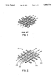
- FIG. 1 illustrates the fluid flow path through a conventional woven cotton scrim
- FIG. 2 illustrates a fluid flow path along a lattice structure of the type used in a scrim according to the present invention
- FIG. 3 is a perspective view partially cur away to show the three layer construction of the filter means of the present invention.
- FIG. 4 illustrates an embodiment of a filter canister including a filter means according ro the present invention adapted for use with a face mask.
- FIG. 1 illustrates a conventional woven scrim material
- the fluid flow path as designated by the arrows is quite tortuous in the plane of the web.
- FIG. 2 illustrates the fluid flow path, again illustrated by arrows, is illustrated.
- the non-woven material used to form the upstream and downstream layers of the novel scrim means 10 according to the invention is made up of first and second rows of filaments 10a and 10b, respectively.
- the filaments of the first row 10a are arranged at an angle to the filaments of the second group 10b of about 90° to form a mesh or lattice structure. Within each group, the filaments are substantially uniformly spaced apart in parallel relationship.
- the first and second rows of filaments 10a and 10b may also be designated as support filaments and drainage filaments, respectively, based upon their function and relative position with respect to the filter medium.
- support filaments refers to those filaments adjacent to the filter medium which serve to support the filter medium.
- drainage filaments refers to those filaments which are joined to the support filaments and are on the outside facing away from the filter medium.
- the diameter of the support and drainage filaments is about the same; and the thickness of the support and drainage layers is about 0.017 to 0.023 inches.
- Adjacent drainage filaments are disposed closely to one another and may contact one another in a non-nesting manner in the pleated configuration to form the main fluid flow paths.
- drainage filaments 10b' on one pleat lie (facing) opposite and transverse with respect to drainage filaments on an adjacent facing pleat 10b 2 .
- the drainage filaments of one pleat may contact the drainage filaments of an adjacent pleat.
- the pleats are parallel and in substantially coextensive contact with each other such that there is extensive drainage filament-to-drainage filament contact.
- the filter means is designated generally by reference numeral 1.
- the filter means includes a filter medium 3 disposed between support and drainage layers 5.
- the support and drainage layers comprise the scrim means.
- the filter means is arranged in a pleated configuration.
- the peaks or apices and the troughs which define the fold lines 7 of the pleats are arranged in the direction of the fluid flow path, that is in axial orientation with respect thereto. More specifically, the upstream apices and downstream apices of the pleats each define a plane, the two planes being substantially parallel to one another.
- the filter medium 3 may be formed from any material which is inert to gases, liquids and solids typically encountered in chemical and biological warfare and which is capable of undergoing processing, such as corrugation, without adverse effects.
- the filter medium can be any suitably porous medium, e.g. a microporous polymeric membrane such as polytetrafluoroethelene or Nylon®66.
- a variety of microfibrous media are also suitable for use in the filter medium 3, including a microfibrous glass fibre filter medium with uniform pores, a microfibrous glass fibre filter medium with graduated pores, e.g. having an upstream layer with larger pores which serve as a course filter and a downstream layer with smaller pores which serves as a finer filter, or a filter medium comprising the combination of a microfibrous glass fibre layer upstream from a microfibrous electret (i.e.
- the fibre filter media may include a suitable binder and may be treated to be both hydrophobic and oleophobic, i.e. to resist wetting by water and oil-based compositions, respectively, and thereby resist plugging and clogging by water and oil aerosols
- a fluorochemical treatment similar to that described in U.S. Pat. No. 4,508,775 to Joseph G. Adiletta for Gas Permeable Composite Structures, may be applied to the glass fibres.
- Suitable materials include glass, polyethylene, polyvinyl chloride, vinyon fibres (vinyon is a generic name for a manufactured fibre in which the fibre-forming substance is any long chain synthetic polymer composed of at least 85% of vinyl chloride units), and combinations thereof.
- the filter medium may also include a water repellant such as a silane, for example, an alkylrrihalosilane and, particularly, methyltrichlorosilane, and a mildewcide such as Yancid®.
- a preferred filter medium is formed, by weight, of 40% glass fibres and 60% vinyon fibres.
- the composition also contains about 1 to about 5%, by weight, based on the total weight of vinyon and glass fibres of methyltrichlorosilane and Vancide®.
- Materials which may be suitably used for the scrim layers 5 of the present invention are inert to microorganisms, such as fungi and molds, of the type which attack cotton scrims.
- such materials are also inert to other microorganisms and chemical reagents which may be used to chemical and biological warfare.
- the materials used to form the scrim layers are preferably easily extruded to form filaments of the dimensions preferred in the present invention and easily assembled to form the scrim layers of the present invention.
- Such materials are preferably thermoplastic Examples of preferred materials include polyolefins, such as polyethylene and polypropylene, preferably the latter.
- fluid flow occurs to a major extent between and parallel to the drainage filaments 10b as well as parallel to the surface of the adjacent filter medium.
- this is due to the uniformly spaced relationship of the filaments in the present invention, maintained by the heat fused or welded contact points where support filaments cross drainage filaments in addition, as noted above, because of the structure, the materials used, and the orientation and contact of the drainage filaments, the support and drainage material of the present invention shows little or no tendency to nest.
- the support filament spacing which prevents deflection or extrusion of the relatively compressible filter medium between the support filaments. This assists in maintaining fluid flow space between and parallel to drainage filaments and also prevents overstressing of the filter medium during manufacture or use.
- the spacing of adjacent filaments in the support and drainage layers is about the same.
- the preferred range of filament spacings is defined as about 15.5 to 17.5 strands per inch.
- the parallel arrangement of support filaments of the present invention allows relatively unhindered fluid flow path and also provides continuous support to the filter medium.
- the support filaments of the scrim layers of the present invention provide continuous support over a greater surface area of the filter medium.
- FIG. 4 shows in section a preferred embodiment of the filter means according to the present invention disposed in a conventional filter canister
- the canister designated generally by reference numeral 11, includes a casing 13 formed from either a plastic or metal material, preferably aluminum.
- the casing is preferably non-conductive and, when manufactured from metal, should be coated on the exterior surface to render it essentially non-conductive.
- the casing which is preferably cylindrical, includes a front wall 15, a rear wall 17, and a cylindrical side wall 19.
- the rear wall which is on the downstream side of the canister, includes a means of attachment to the face mask which typically takes the form of a cylindrical protrusion 21 having external threads 23 which allow the canister 11 to be threaded into a commensurate fitting in the face mask (not shown).
- Both the rear portion of the cylindrical protrusion 21, which is received in the face mask, and the front wall 15 include apertures to permit ingress and egress of gases.
- the apertures (not shown) ar generally evenly distributed over the surface.
- the pleated filter means 1 for removing particulates and aerosols from the breathing gas is located within the housing and is sealingly retained by edge seal 25 (formed from a polyurethane material). It is also maintained in place by perforated retainers 27 and 29 arranged on the upstream and downstream sides, respectively, of the filter means 1. These retainers, and particularly the upstream retainer 27 restrain the porous means and protect it from damage occurring by mechanical intrusion through the inlet apertures (not shown).
- a sorbent bed (second) filter means 31 is disposed within the housing downstream from the particulate/aerosol filter assembly 1.
- the sorbent bed filter assembly 31 typically includes a compressively-loaded bed of activated carbon particles, preferably of a size of about 12 ⁇ 30 mesh U.S. Sieve Series.
- the bed could be fashioned from any suitable sorbent material of suitable particle size, i.e. a material which absorbs or adsorbs the vaporous chemical contaminants, such as activated alumina, ion exchange resins, or molecular sieves.
- fines filters 35 and 37 are included Immediately adjacent and located upstream and downstream of the second filter means 31, are included fines filters 35 and 37.
- a perforated retainer plate 39 is placed in contact with the fines filter 37 on the downstream side of the sorbent bed 31.
- the filter medium paper was comprised, by weight, of 40% of type 475 glass fibres and 60% vinyon (H. H. regular, 3 denier by 6.35 mm long.
- the medium also contains about 1 to 5%, by weight, based on the total weight of vinyon and glass fibres, of methyltrichlorosilane (Dow Corning, Z1211), and Yancide® (89 - R.T. vanderbilt).
- the filter medium was supplied in a thickness of about 0.35 mm.
- the scrim material was supplied in 24 inch wide rolls of polypropylene mesh in which both the support and drainage filaments were parallel and spaced from one another to provide about 16 filaments per inch. Each of the filaments had a diameter of about 0.010 inches.
- the corrugator was adjusted to provide a pleat height (distance between adjacent fold lines) of about 0.56 inches. After passing through the corrugator device, the pleated porous means (particulate filter) was passed between two heated plates at a temperature just below the melting point of the synthetic polymeric non-woven support and drainage material (polypropylene), i.e. 200° to 235° F.
- the pleated porous means (particulate filter) had a pleat arrangement of 11 pleats per inch.
- the frame was then placed onto a manipulator provided with a series of jet nozzles capable of supplying water jets at 55,000 psi.
- Several particulate filters were cut from the pleated material in the frame with the water jets.
- the filters were placed into particulate filter retainers which were then transferred to spin molds.
- Polyurethane was introduced to the retainers as they were rotated at a speed of about 1,500 to about 3,000 RPM. The polyurethane formed a seal between the peripheral circumference of the filter and the inner surface of the retainer wall. Spinning was continued until the urethane cured.
Abstract
The invention disclosed is an improved scrim means for use in a breathing gas filter assembly which includes a pleated web filter medium. The improved scrim means is of a non-woven microorganism resistant synthetic polymeric material of sufficient rigidity to provide substantially continuous support to maintain the pleats of the filter medium in substantially uniformly spaced relationship, to expedite fluid flow in the plane of the web and to minimize nesting of the filter medium.
Description
The present invention relates to breathing gas filter systems for removing undesirable substances from a breathing gas, and in particular to an improved filter means capable of removing particulate and liquid aerosol contaminants from a breathing gas, i.e. an oxygen-containing gas capable of supporting life.
In a variety of military and industrial settings a person may require a gas mask when in an environment of highly toxic airborne contaminants, including particulate, aerosol and vaporous chemical and biological contaminants. The gas mask commonly includes a face cover and a breathing gas filter assembly attached thereto.
Typical breathing gas filter assemblies contain two primary filter means. A first filter means includes a filter medium for removal of particulate and liquid aerosol contaminants from the breathing gas, followed by a second filter means including a sorbent material for removing chemical contaminants present as vapours or in the gaseous state. The present invention is concerned with improvement of the first filter means.
Filter means of this type normally include a porous filter medium, such as glass fibres, other inert fibres or a combination thereof, in the form of a web. Commonly, the filter medium is in a pleared form in order to provide maximum possible surface area and filtration efficiency in a given space envelope When such a configuration is employed, the filter means may also include scrim means, i.e. layers of material both at the upstream and downstream surfaces of the filter medium to provide support for the filter medium which may, in some instances, be of a material not capable of self- support. The scrim means is also intended to optimize fluid flow through the filter means and drainage of liquids such as those which result during aerosol removal.
A woven cotton scrim is typically employed. However, in cotton scrims, the fluid flow path is very tortuous in the plane of the web. This results in a higher pressure drop and a longer, less efficient fluid flow path with concomitant increased resistance to fluid flow and non-uniform fluid flow through the filter medium which detracts from filter efficiency.
Furthermore, woven materials inherently tend to "nest" when folded back upon themselves in the form of a pleated configuration. This is due to the "knuckles", that is, the raised portions of the material formed where one filament of the material crosses transversely over another filament, engaging recesses formed between knuckles. Because of the tendency of woven materials when folded over on themselves to nest, forming a two layer thickness less than twice the thickness of a single layer, the system suffers a further reduction in efficiency for pleated configurations.
Although the tortuous nature of the fluid flow path through woven cotton scrims may be reduced somewhat by increasing the spacing between adjacent filaments of the material, the efficiency of the filter means correspondingly decreases due to an increased tendency for the cotton scrim to nest. Furthermore, the nature of the cotton material often results in non-uniform spacing between the filaments with concomitant variations in fluid flow velocity and decreased fluid flow efficiency.
Additionally, the relatively widely spaced woven scrim is a less than optimum mechanical support structure for the filter medium since (a) the knuckles formed by weaving present high load contact points which can perforate the filter medium during manufacture or in rough handling, and (b) the large space between filaments may permit the filter medium to squeeze between filaments and through the scrim to thereby reduce the fluid flow efficiency.
Furthermore, cotton, under certain conditions of temperature and humidity is readily attacked by microorganisms such as molds and fungi. Such microorganisms ultimately tend to consume and weaken the cotton, thereby rendering it ineffective as a scrim material. In some instances, the presence of microorganisms, such as mildew, may be accompanied by undesirable dank odours produced by such microorganisms To eliminate such problems, fungicides have been applied to the cotton scrim material to deter attack However, in many instances, a fungicide may be somewhat specific and ineffective in controlling all fungi or molds capable of attacking cotton. Since the standard test used in assurance testing of filter canisters employs a single microorganism, full protection against all microorganisms cannot be assured when cotton scrims form part of the filter means. Furthermore, many fungicides may act as irritants to the mask wearer as well as the personnel manufacturing the mask.
To avoid problems with scrim materials altogether, various materials have been selected for or used in treatments applied to the filter medium which were considered to provide sufficient rigidity to render separate supporting layers unnecessary. Development in technology relating to self-support has also attempted to maintain the pleats in an open and uniformly spaced relationship to one another. Such attempts have included (1) impregnating the filter medium with a material to provide rigidity, and (2) the use of filter material having larger diameter filaments to increase bending modulus thereof. Both (1) and (2) have negative performance factors in the they reduce total material surface area and voids volume which is contrary to good filtration performance. Breathing gas filter canisters provided with such filter media suffer a further drawback in that it is generally difficult to precisely space and maintain the pleats in the desired uniformly-spaced relationship, typically 0.01 to 0.02 inch. The imprecise spacing produces uneven fluid flow distribution which increases fluid flow resistance that causes increased fluid velocity at certain locations and results ultimately in decreased filter efficiency. In addition, if extreme care is not used in handling the material, and in the use of completed filter canisters, the pleats may be deflected resulting in some pleats being pinched off, which produces increased fluid flow resistance and loss of filter efficiency.
According to the invention an improved breathing gas filter means for removing undesirable contaminants in particulate and aerosol form from a breathing gas, for use in a breathing gas filter assembly in conjunction with a gas mask, said filter assembly comprising a casing and said breathing gas filter means contained therein, wherein said breathing gas filter means is of a pleated web configuration, including a filter medium and scrim means defined by layers of material both at the upstream and downstream surfaces of the filter medium, the improvement wherein said scrim material is of a non-woven microorganism resistant synthetic polymeric material to provide substantially continuous support for said filter medium and is of sufficient rigidity to maintain the pleats in substantially uniformly spaced relationship, to expedite fluid flow in the plane of the web and to minimize nesting of the filter medium.
The scrim layers sandwiching the porous filter medium are comprised of a microorganism-resistant, synthetic polymeric non-woven material These layers are both formed from first and second rows of filaments in which the filaments in each row are disposed parallel and in substantially uniformly spaced relationship to one another.
Preferably the peaks or apices and the troughs which define the fold lines of the pleats in the filter medium are arranged in parallel planes. The first and second rows of filaments are preferably arranged at an angle of about 90° to one another and in this pleated configuration are therefore oriented at an angle of about 42°-45° to the fold line of the parallel pleats.
In the drawing which illustrates the preferred embodiment of the invention,
FIG. 1 illustrates the fluid flow path through a conventional woven cotton scrim;
FIG. 2 illustrates a fluid flow path along a lattice structure of the type used in a scrim according to the present invention;
FIG. 3 is a perspective view partially cur away to show the three layer construction of the filter means of the present invention; and
FIG. 4 illustrates an embodiment of a filter canister including a filter means according ro the present invention adapted for use with a face mask.
With specific reference to the drawing, it is seen in FIG. 1, which illustrates a conventional woven scrim material, that the fluid flow path, as designated by the arrows is quite tortuous in the plane of the web. The advantage of using a nonwoven scrim material is evident from FIG. 2, wherein the fluid flow path, again illustrated by arrows, is illustrated. More specifically, the non-woven material used to form the upstream and downstream layers of the novel scrim means 10 according to the invention is made up of first and second rows of filaments 10a and 10b, respectively. The filaments of the first row 10a are arranged at an angle to the filaments of the second group 10b of about 90° to form a mesh or lattice structure. Within each group, the filaments are substantially uniformly spaced apart in parallel relationship.
The first and second rows of filaments 10a and 10b may also be designated as support filaments and drainage filaments, respectively, based upon their function and relative position with respect to the filter medium. Thus, the term "support filaments" refers to those filaments adjacent to the filter medium which serve to support the filter medium. The term "drainage filaments" refers to those filaments which are joined to the support filaments and are on the outside facing away from the filter medium.
Preferably, the diameter of the support and drainage filaments is about the same; and the thickness of the support and drainage layers is about 0.017 to 0.023 inches.
Adjacent drainage filaments are disposed closely to one another and may contact one another in a non-nesting manner in the pleated configuration to form the main fluid flow paths. Thus, as shown in FIG. 3, drainage filaments 10b' on one pleat lie (facing) opposite and transverse with respect to drainage filaments on an adjacent facing pleat 10b2. When the filter medium is tightly corrugated to provide closely spaced pleats, the drainage filaments of one pleat may contact the drainage filaments of an adjacent pleat. For example, as is common in a filter canister of a gas mask in which the particulate and aerosol filter assembly is planar, the pleats are parallel and in substantially coextensive contact with each other such that there is extensive drainage filament-to-drainage filament contact.
As seen in FIG. 3, the filter means is designated generally by reference numeral 1. The filter means includes a filter medium 3 disposed between support and drainage layers 5. The support and drainage layers comprise the scrim means. The filter means is arranged in a pleated configuration.
In the preferred embodiment, the peaks or apices and the troughs which define the fold lines 7 of the pleats are arranged in the direction of the fluid flow path, that is in axial orientation with respect thereto. More specifically, the upstream apices and downstream apices of the pleats each define a plane, the two planes being substantially parallel to one another.
The filter medium 3 may be formed from any material which is inert to gases, liquids and solids typically encountered in chemical and biological warfare and which is capable of undergoing processing, such as corrugation, without adverse effects.
The filter medium can be any suitably porous medium, e.g. a microporous polymeric membrane such as polytetrafluoroethelene or Nylon®66. A variety of microfibrous media are also suitable for use in the filter medium 3, including a microfibrous glass fibre filter medium with uniform pores, a microfibrous glass fibre filter medium with graduated pores, e.g. having an upstream layer with larger pores which serve as a course filter and a downstream layer with smaller pores which serves as a finer filter, or a filter medium comprising the combination of a microfibrous glass fibre layer upstream from a microfibrous electret (i.e. a microfibrous material capable of maintaining a static electric charge) The fibre filter media may include a suitable binder and may be treated to be both hydrophobic and oleophobic, i.e. to resist wetting by water and oil-based compositions, respectively, and thereby resist plugging and clogging by water and oil aerosols For example, a fluorochemical treatment, similar to that described in U.S. Pat. No. 4,508,775 to Joseph G. Adiletta for Gas Permeable Composite Structures, may be applied to the glass fibres.
Other examples of suitable materials include glass, polyethylene, polyvinyl chloride, vinyon fibres (vinyon is a generic name for a manufactured fibre in which the fibre-forming substance is any long chain synthetic polymer composed of at least 85% of vinyl chloride units), and combinations thereof. The filter medium may also include a water repellant such as a silane, for example, an alkylrrihalosilane and, particularly, methyltrichlorosilane, and a mildewcide such as Yancid®. A preferred filter medium is formed, by weight, of 40% glass fibres and 60% vinyon fibres. The composition also contains about 1 to about 5%, by weight, based on the total weight of vinyon and glass fibres of methyltrichlorosilane and Vancide®.
Materials which may be suitably used for the scrim layers 5 of the present invention are inert to microorganisms, such as fungi and molds, of the type which attack cotton scrims. Preferably, such materials are also inert to other microorganisms and chemical reagents which may be used to chemical and biological warfare. In addition, the materials used to form the scrim layers are preferably easily extruded to form filaments of the dimensions preferred in the present invention and easily assembled to form the scrim layers of the present invention. Such materials are preferably thermoplastic Examples of preferred materials include polyolefins, such as polyethylene and polypropylene, preferably the latter.
As indicated by the arrows in FIG. 2, fluid flow occurs to a major extent between and parallel to the drainage filaments 10b as well as parallel to the surface of the adjacent filter medium. In part this is due to the uniformly spaced relationship of the filaments in the present invention, maintained by the heat fused or welded contact points where support filaments cross drainage filaments in addition, as noted above, because of the structure, the materials used, and the orientation and contact of the drainage filaments, the support and drainage material of the present invention shows little or no tendency to nest.
Efficiency is further enhanced in the present invention by the support filament spacing which prevents deflection or extrusion of the relatively compressible filter medium between the support filaments. This assists in maintaining fluid flow space between and parallel to drainage filaments and also prevents overstressing of the filter medium during manufacture or use. Preferably, the spacing of adjacent filaments in the support and drainage layers is about the same. The preferred range of filament spacings is defined as about 15.5 to 17.5 strands per inch.
In addition to minimizing fluid flow resistance caused by cross filaments in the direct fluid flow path, such as in the woven cotton scrim of FIG. 1, the parallel arrangement of support filaments of the present invention allows relatively unhindered fluid flow path and also provides continuous support to the filter medium. Unlike the stressful point contacts associated with woven mesh such as scrim, which may cause damage to the filter medium during production and/or service, the support filaments of the scrim layers of the present invention provide continuous support over a greater surface area of the filter medium.
FIG. 4 shows in section a preferred embodiment of the filter means according to the present invention disposed in a conventional filter canister The canister, designated generally by reference numeral 11, includes a casing 13 formed from either a plastic or metal material, preferably aluminum. The casing is preferably non-conductive and, when manufactured from metal, should be coated on the exterior surface to render it essentially non-conductive. The casing which is preferably cylindrical, includes a front wall 15, a rear wall 17, and a cylindrical side wall 19. The rear wall, which is on the downstream side of the canister, includes a means of attachment to the face mask which typically takes the form of a cylindrical protrusion 21 having external threads 23 which allow the canister 11 to be threaded into a commensurate fitting in the face mask (not shown). Alternate means of attachment, such as a bayonet fitting or the like, may be employed. Both the rear portion of the cylindrical protrusion 21, which is received in the face mask, and the front wall 15 include apertures to permit ingress and egress of gases. The apertures (not shown) ar generally evenly distributed over the surface.
The pleated filter means 1 according to the invention for removing particulates and aerosols from the breathing gas is located within the housing and is sealingly retained by edge seal 25 (formed from a polyurethane material). It is also maintained in place by perforated retainers 27 and 29 arranged on the upstream and downstream sides, respectively, of the filter means 1. These retainers, and particularly the upstream retainer 27 restrain the porous means and protect it from damage occurring by mechanical intrusion through the inlet apertures (not shown).
A sorbent bed (second) filter means 31 is disposed within the housing downstream from the particulate/aerosol filter assembly 1. To efficiently remove vaporous chemical contaminants the sorbent bed filter assembly 31 typically includes a compressively-loaded bed of activated carbon particles, preferably of a size of about 12×30 mesh U.S. Sieve Series. However, the bed could be fashioned from any suitable sorbent material of suitable particle size, i.e. a material which absorbs or adsorbs the vaporous chemical contaminants, such as activated alumina, ion exchange resins, or molecular sieves.
Immediately adjacent and located upstream and downstream of the second filter means 31, are included fines filters 35 and 37. A perforated retainer plate 39 is placed in contact with the fines filter 37 on the downstream side of the sorbent bed 31.
While the invention is susceptible to various modifications and alternative forms, certain specific embodiments thereof are described in the examples set forth below. It should be understood, however, that these examples are not intended to limit the invention to the particular forms disclosed but, on the contrary, the intention is to cover all modifications, equivalents, and alternatives falling within the spirit and scope of this invention.
Rolls of porous filter medium and scrim material were arranged in front of a corrugator device so that one layer of filter medium paper was supplied to the corrugator device interposed between two layers of scrim material. The filter medium paper was comprised, by weight, of 40% of type 475 glass fibres and 60% vinyon (H. H. regular, 3 denier by 6.35 mm long. The medium also contains about 1 to 5%, by weight, based on the total weight of vinyon and glass fibres, of methyltrichlorosilane (Dow Corning, Z1211), and Yancide® (89 - R.T. vanderbilt). The filter medium was supplied in a thickness of about 0.35 mm. The scrim material was supplied in 24 inch wide rolls of polypropylene mesh in which both the support and drainage filaments were parallel and spaced from one another to provide about 16 filaments per inch. Each of the filaments had a diameter of about 0.010 inches. The corrugator was adjusted to provide a pleat height (distance between adjacent fold lines) of about 0.56 inches. After passing through the corrugator device, the pleated porous means (particulate filter) was passed between two heated plates at a temperature just below the melting point of the synthetic polymeric non-woven support and drainage material (polypropylene), i.e. 200° to 235° F. The pleated porous means (particulate filter) had a pleat arrangement of 11 pleats per inch.
A portion of filter means or particulate filter prepared in Example 1, having dimensions of 24 inches × 60 inches, was cut and placed into a frame which maintained the number of pleats at eleven pleats per inch. The frame was then placed onto a manipulator provided with a series of jet nozzles capable of supplying water jets at 55,000 psi. Several particulate filters were cut from the pleated material in the frame with the water jets. The filters were placed into particulate filter retainers which were then transferred to spin molds. Polyurethane was introduced to the retainers as they were rotated at a speed of about 1,500 to about 3,000 RPM. The polyurethane formed a seal between the peripheral circumference of the filter and the inner surface of the retainer wall. Spinning was continued until the urethane cured.
Claims (12)
1. In a breathing gas filter assembly for use with a gas mask, said filter assembly comprising a casing and a breathing gas filter means contained therein for removing undesirable contaminants in particulate and aerosol form from said breathing gas, wherein said breathing gas filter means is of a pleated web configuration, including a filter medium and scrim means defined by layers of material both at the upstream and downstream surfaces of the filter medium, the improvement wherein said scrim means is of a non-woven microorganism resistant synthetic polymeric material to provide substantially continuous support for said filter medium and is of sufficient rigidity to maintain the pleats in substantially uniformly spaced relationship, to expedite fluid flow in the plane of the web and to minimize nesting of the filter medium.
2. A breathing gas filter assembly according to claim 1, wherein said scrim material is formed from first and second rows of filaments, the rows of filaments being heat sealed together, such that the filaments in each row are disposed parallel and in substantially uniformly spaced relationship to one another.
3. A breathing gas filter assembly according to claim 2, wherein the filaments in the first row are arranged at about 90° to the filaments in the second row.
4. A breathing gas filter assembly according to claim 3, wherein the peaks and troughs which define fold lines of the pleats of said breathing gas filter means are arranged in parallel planes.
5. A breathing gas filter assembly according to claim 4, wherein the first and second rows of filaments are oriented at an angle of about 42° to 45° to the fold lines of the pleats.
6. A breathing gas filter assembly according to claim 5, wherein the diameter of the filaments in each of the first and second rows is about the same.
7. A breathing gas filter assembly according to claim 6, wherein the spacing of adjacent filaments in the first and second rows is about the same.
8. A breathing gas filter assembly according to claim 7, wherein the filaments in each of the first and second rows are arranged at spacings of about 15.5 to 17.5 strands per inch.
9. A breathing gas filter assembly according to claim 8, wherein the filter medium comprises, by weight, of 40% glass fibres and 60% vinyon fibres.
10. A breathing gas filter assembly according to claim 9, wherein the synthetic polymeric material is a thermoplastic material.
11. A breathing gas filter assembly according to claim 10, wherein the thermoplastic material is a polyolefin.
12. A breathing gas filter assembly according to claim 11, wherein the polyolefin is polypropylene.
Priority Applications (2)
| Application Number | Priority Date | Filing Date | Title |
|---|---|---|---|
| US07/140,677 US5038775A (en) | 1988-01-04 | 1988-01-04 | Plastic scrim |
| CA000574901A CA1306201C (en) | 1988-01-04 | 1988-08-16 | Plastic scrim |
Applications Claiming Priority (1)
| Application Number | Priority Date | Filing Date | Title |
|---|---|---|---|
| US07/140,677 US5038775A (en) | 1988-01-04 | 1988-01-04 | Plastic scrim |
Publications (1)
| Publication Number | Publication Date |
|---|---|
| US5038775A true US5038775A (en) | 1991-08-13 |
Family
ID=22492333
Family Applications (1)
| Application Number | Title | Priority Date | Filing Date |
|---|---|---|---|
| US07/140,677 Expired - Fee Related US5038775A (en) | 1988-01-04 | 1988-01-04 | Plastic scrim |
Country Status (2)
| Country | Link |
|---|---|
| US (1) | US5038775A (en) |
| CA (1) | CA1306201C (en) |
Cited By (38)
| Publication number | Priority date | Publication date | Assignee | Title |
|---|---|---|---|---|
| US5619989A (en) * | 1994-03-26 | 1997-04-15 | Dragerwerk Ag | Respirator filter |
| GB2306346A (en) * | 1995-10-27 | 1997-05-07 | Titus Int Plc | Filtering apparatus for use in respirators |
| US5639700A (en) * | 1992-08-04 | 1997-06-17 | Minnesota Mining And Manufacturing Company | Thermal insulation containing corrugated nonwoven web of polymeric microfiber |
| US5645627A (en) * | 1995-02-28 | 1997-07-08 | Hollingsworth & Vose Company | Charge stabilized electret filter media |
| US5647356A (en) * | 1993-07-28 | 1997-07-15 | Donaldson Company, Inc. | Respirator cartridge with sealing fit test structure and method of use |
| US5727616A (en) * | 1995-10-27 | 1998-03-17 | Edentec | Elastomeric heat exchanger bed |
| US5732695A (en) * | 1997-03-11 | 1998-03-31 | Parmelee Industries | Respirator filtration device |
| US5792242A (en) * | 1996-02-26 | 1998-08-11 | Minnesota Mining And Manufacturing Co. | Electrostatic fibrous filter web |
| US5871836A (en) * | 1997-08-27 | 1999-02-16 | Airflo Europe N.V. | Composite pleated fibrous structures containing split film fibers |
| US6211100B1 (en) | 1996-04-30 | 2001-04-03 | Minnesota Mining And Manufacturing Company | Synthetic filter media |
| US6209541B1 (en) | 1998-02-25 | 2001-04-03 | Sims Portex Inc. | Hydrophobic electrostatic breathing filters, and methods of manufacturing the same |
| US6254653B1 (en) | 1999-10-08 | 2001-07-03 | Aaf International | Pleated fluid filter medium blend |
| US20020187701A1 (en) * | 2001-05-02 | 2002-12-12 | Hollingsworth & Vose Company | Filter media with enhanced stiffness and increased dust holding capacity |
| US6524360B2 (en) | 2000-02-15 | 2003-02-25 | Hollingsworth & Vose Company | Melt blown composite HEPA filter media and vacuum bag |
| US20030203696A1 (en) * | 2002-04-30 | 2003-10-30 | Healey David Thomas | High efficiency ashrae filter media |
| FR2840233A1 (en) * | 2002-05-28 | 2003-12-05 | Giat Ind Sa | Method of assembling a filter cartridge with a seal being formed between the paper filter and the casing and the cover stuck to the casing simultaneously |
| US20040055604A1 (en) * | 2002-09-23 | 2004-03-25 | Viner Andrew S. | Filter element that has a thermo-formed housing around filter material |
| US20040118545A1 (en) * | 2002-12-19 | 2004-06-24 | Bakken Andrew Peter | Non-woven through air dryer and transfer fabrics for tissue making |
| US20040118546A1 (en) * | 2002-12-19 | 2004-06-24 | Bakken Andrew Peter | Non-woven through air dryer and transfer fabrics for tissue making |
| US6761169B2 (en) * | 2000-08-17 | 2004-07-13 | Vase Technology | Bi/multi-directional filter cartridge and filter platform for mounting the cartridge thereon |
| US20040216745A1 (en) * | 2003-04-30 | 2004-11-04 | Yuen Peter Siltex | Electronic human breath filtration device |
| US20050067125A1 (en) * | 2003-09-26 | 2005-03-31 | Kimberly-Clark Worldwide, Inc. | Method of making paper using reformable fabrics |
| US20060292947A1 (en) * | 2005-06-24 | 2006-12-28 | Lavietes Daniel | Polyester fiber scrim and method for making same |
| US20070056589A1 (en) * | 2000-04-18 | 2007-03-15 | Avon Rubber And Plastics, Inc. | Multi-stage respirator filter with tim filter option |
| US20070144123A1 (en) * | 2005-12-22 | 2007-06-28 | Angadjivand Seyed A | Filter Element That Has Plenum Containing Bonded Continuous Filaments |
| US20070283951A1 (en) * | 2006-06-12 | 2007-12-13 | Marc Alan Burk | Mask-nebulizer assembly |
| WO2008081489A1 (en) * | 2007-01-05 | 2008-07-10 | Officine Meccaniche Galli S.R.L. | Nbc filter |
| US20090061522A1 (en) * | 2007-08-29 | 2009-03-05 | Collins Sr Michael J | Automated Protein Analyzer |
| US20090087917A1 (en) * | 2007-08-29 | 2009-04-02 | Cem Corporation | Automated protein analyzer |
| US20090120440A1 (en) * | 2004-11-24 | 2009-05-14 | Intersurgical Ag | Respiratory circuits |
| US20100212272A1 (en) * | 2009-02-24 | 2010-08-26 | Hollingsworth & Vose Company | Filter media suitable for ashrae applications |
| US20110036353A1 (en) * | 2009-08-14 | 2011-02-17 | Moldex-Metric, Inc. | Filter material and respirator mask |
| US20110041843A1 (en) * | 2009-08-20 | 2011-02-24 | Jenkins Eddie Dewayne | Adaptor and breathing assist device using the same |
| US20110308524A1 (en) * | 2008-12-22 | 2011-12-22 | Brey Larry A | Compact multigas filter |
| US20130075347A1 (en) * | 2011-09-20 | 2013-03-28 | Clarification Technology, Inc. | Filtration device for cooking oil |
| US20140041348A1 (en) * | 2012-08-07 | 2014-02-13 | Honeywell International Inc. | Accessory cap for a respiratory filter cartridge |
| US10279303B2 (en) * | 2003-12-22 | 2019-05-07 | Donaldson Company, Inc. | Seal arrangement for filter element; filter element assembly; and, methods |
| WO2022068072A1 (en) * | 2020-09-29 | 2022-04-07 | 广州拜费尔空气净化材料有限公司 | Filter device |
Citations (9)
| Publication number | Priority date | Publication date | Assignee | Title |
|---|---|---|---|---|
| FR749284A (en) * | 1932-04-13 | 1933-07-21 | Cell filter device or removable and conjugate elements for breathing apparatus and other applications | |
| US2201315A (en) * | 1936-11-13 | 1940-05-21 | American Optical Corp | Respirator |
| US2269461A (en) * | 1939-11-02 | 1942-01-13 | American Optical Corp | Respirator |
| US3944403A (en) * | 1973-02-28 | 1976-03-16 | Siebe Gorman & Company Limited | Adsorptive devices |
| US4084949A (en) * | 1975-11-06 | 1978-04-18 | The Dexter Corporation | Surgical face mask filtering medium |
| US4508113A (en) * | 1984-03-09 | 1985-04-02 | Chicopee | Microfine fiber laminate |
| US4548626A (en) * | 1984-04-30 | 1985-10-22 | Figgie International Inc. | Particulate air filter assembly |
| US4643182A (en) * | 1983-04-20 | 1987-02-17 | Max Klein | Disposable protective mask |
| US4714486A (en) * | 1985-07-03 | 1987-12-22 | Her Majesty The Queen In Right Of Canada | Automated production of canisters |
-
1988
- 1988-01-04 US US07/140,677 patent/US5038775A/en not_active Expired - Fee Related
- 1988-08-16 CA CA000574901A patent/CA1306201C/en not_active Expired - Lifetime
Patent Citations (9)
| Publication number | Priority date | Publication date | Assignee | Title |
|---|---|---|---|---|
| FR749284A (en) * | 1932-04-13 | 1933-07-21 | Cell filter device or removable and conjugate elements for breathing apparatus and other applications | |
| US2201315A (en) * | 1936-11-13 | 1940-05-21 | American Optical Corp | Respirator |
| US2269461A (en) * | 1939-11-02 | 1942-01-13 | American Optical Corp | Respirator |
| US3944403A (en) * | 1973-02-28 | 1976-03-16 | Siebe Gorman & Company Limited | Adsorptive devices |
| US4084949A (en) * | 1975-11-06 | 1978-04-18 | The Dexter Corporation | Surgical face mask filtering medium |
| US4643182A (en) * | 1983-04-20 | 1987-02-17 | Max Klein | Disposable protective mask |
| US4508113A (en) * | 1984-03-09 | 1985-04-02 | Chicopee | Microfine fiber laminate |
| US4548626A (en) * | 1984-04-30 | 1985-10-22 | Figgie International Inc. | Particulate air filter assembly |
| US4714486A (en) * | 1985-07-03 | 1987-12-22 | Her Majesty The Queen In Right Of Canada | Automated production of canisters |
Cited By (75)
| Publication number | Priority date | Publication date | Assignee | Title |
|---|---|---|---|---|
| US5763078A (en) * | 1992-08-04 | 1998-06-09 | Minnesota Mining And Manufacturing Company | Filter having corrugated nonwoven webs of polymeric microfiber |
| US6010766A (en) * | 1992-08-04 | 2000-01-04 | 3M Innovative Properties Company | Corrugated nonwoven webs of polymeric microfiber |
| US5639700A (en) * | 1992-08-04 | 1997-06-17 | Minnesota Mining And Manufacturing Company | Thermal insulation containing corrugated nonwoven web of polymeric microfiber |
| US5955193A (en) * | 1992-08-04 | 1999-09-21 | Minnesota Mining And Manufacturing Company | Apparel containing corrugated microfiber-containing thermal insulation |
| US5656368A (en) * | 1992-08-04 | 1997-08-12 | Minnesota Mining And Manufacturing Company | Fibrous filtration face mask having corrugated polymeric microfiber filter layer |
| US5804295A (en) * | 1992-08-04 | 1998-09-08 | Minnesota Mining And Manufacturing Company | Fibrous filtration face mask having corrugated polymeric microfiber filter layer |
| US5753343A (en) * | 1992-08-04 | 1998-05-19 | Minnesota Mining And Manufacturing Company | Corrugated nonwoven webs of polymeric microfiber |
| US5647356A (en) * | 1993-07-28 | 1997-07-15 | Donaldson Company, Inc. | Respirator cartridge with sealing fit test structure and method of use |
| US5619989A (en) * | 1994-03-26 | 1997-04-15 | Dragerwerk Ag | Respirator filter |
| US5645627A (en) * | 1995-02-28 | 1997-07-08 | Hollingsworth & Vose Company | Charge stabilized electret filter media |
| US6780226B1 (en) * | 1995-02-28 | 2004-08-24 | Hollingsowrth & Vose Company | Charge stabilized electret filter media |
| US5727616A (en) * | 1995-10-27 | 1998-03-17 | Edentec | Elastomeric heat exchanger bed |
| GB2306346A (en) * | 1995-10-27 | 1997-05-07 | Titus Int Plc | Filtering apparatus for use in respirators |
| US5792242A (en) * | 1996-02-26 | 1998-08-11 | Minnesota Mining And Manufacturing Co. | Electrostatic fibrous filter web |
| US6211100B1 (en) | 1996-04-30 | 2001-04-03 | Minnesota Mining And Manufacturing Company | Synthetic filter media |
| US5732695A (en) * | 1997-03-11 | 1998-03-31 | Parmelee Industries | Respirator filtration device |
| US5871836A (en) * | 1997-08-27 | 1999-02-16 | Airflo Europe N.V. | Composite pleated fibrous structures containing split film fibers |
| US6209541B1 (en) | 1998-02-25 | 2001-04-03 | Sims Portex Inc. | Hydrophobic electrostatic breathing filters, and methods of manufacturing the same |
| US6254653B1 (en) | 1999-10-08 | 2001-07-03 | Aaf International | Pleated fluid filter medium blend |
| US6398839B2 (en) | 1999-10-08 | 2002-06-04 | Aaf International | Pleated fluid filter medium frame |
| US6524360B2 (en) | 2000-02-15 | 2003-02-25 | Hollingsworth & Vose Company | Melt blown composite HEPA filter media and vacuum bag |
| US7213595B2 (en) * | 2000-04-18 | 2007-05-08 | Avon Protection Systems, Inc. | Multi-stage respirator filter with TIM filter option |
| US20070056589A1 (en) * | 2000-04-18 | 2007-03-15 | Avon Rubber And Plastics, Inc. | Multi-stage respirator filter with tim filter option |
| US6761169B2 (en) * | 2000-08-17 | 2004-07-13 | Vase Technology | Bi/multi-directional filter cartridge and filter platform for mounting the cartridge thereon |
| US20020187701A1 (en) * | 2001-05-02 | 2002-12-12 | Hollingsworth & Vose Company | Filter media with enhanced stiffness and increased dust holding capacity |
| US20030203696A1 (en) * | 2002-04-30 | 2003-10-30 | Healey David Thomas | High efficiency ashrae filter media |
| FR2840233A1 (en) * | 2002-05-28 | 2003-12-05 | Giat Ind Sa | Method of assembling a filter cartridge with a seal being formed between the paper filter and the casing and the cover stuck to the casing simultaneously |
| US6874499B2 (en) * | 2002-09-23 | 2005-04-05 | 3M Innovative Properties Company | Filter element that has a thermo-formed housing around filter material |
| US20050161045A1 (en) * | 2002-09-23 | 2005-07-28 | 3M Innovative Properties Company | Method of making a filter cartridge that uses thermoforming step |
| US7497217B2 (en) | 2002-09-23 | 2009-03-03 | 3M Innovative Properties Company | Method of making a filter cartridge using a thermoforming step |
| US20040055604A1 (en) * | 2002-09-23 | 2004-03-25 | Viner Andrew S. | Filter element that has a thermo-formed housing around filter material |
| US20060081349A1 (en) * | 2002-12-19 | 2006-04-20 | Bakken Andrew P | Non-woven through air dryer and transfer fabrics for tissue making |
| US6878238B2 (en) | 2002-12-19 | 2005-04-12 | Kimberly-Clark Worldwide, Inc. | Non-woven through air dryer and transfer fabrics for tissue making |
| US7294238B2 (en) | 2002-12-19 | 2007-11-13 | Kimberly-Clark Worldwide, Inc. | Non-woven through air dryer and transfer fabrics for tissue making |
| US20040118546A1 (en) * | 2002-12-19 | 2004-06-24 | Bakken Andrew Peter | Non-woven through air dryer and transfer fabrics for tissue making |
| EP1950343A1 (en) | 2002-12-19 | 2008-07-30 | Kimberly-Clark Worldwide, Inc. | Non-woven through air dryer and transfer fabrics for tissue making |
| US20040118545A1 (en) * | 2002-12-19 | 2004-06-24 | Bakken Andrew Peter | Non-woven through air dryer and transfer fabrics for tissue making |
| US6875315B2 (en) | 2002-12-19 | 2005-04-05 | Kimberly-Clark Worldwide, Inc. | Non-woven through air dryer and transfer fabrics for tissue making |
| EP1932968A2 (en) | 2002-12-19 | 2008-06-18 | Kimberly-Clark Worldwide, Inc. | Non-woven through air dryer and transfer fabrics for tissue making |
| US20040216745A1 (en) * | 2003-04-30 | 2004-11-04 | Yuen Peter Siltex | Electronic human breath filtration device |
| US7392806B2 (en) * | 2003-04-30 | 2008-07-01 | Peter Siltex Yuen | Electronic human breath filtration device |
| US7141142B2 (en) | 2003-09-26 | 2006-11-28 | Kimberly-Clark Worldwide, Inc. | Method of making paper using reformable fabrics |
| US20050067125A1 (en) * | 2003-09-26 | 2005-03-31 | Kimberly-Clark Worldwide, Inc. | Method of making paper using reformable fabrics |
| US11123676B2 (en) | 2003-12-22 | 2021-09-21 | Donaldson Company, Inc. | Seal arrangement for filter element; filter element assembly; and, methods |
| US10279303B2 (en) * | 2003-12-22 | 2019-05-07 | Donaldson Company, Inc. | Seal arrangement for filter element; filter element assembly; and, methods |
| US20090120440A1 (en) * | 2004-11-24 | 2009-05-14 | Intersurgical Ag | Respiratory circuits |
| US20060292947A1 (en) * | 2005-06-24 | 2006-12-28 | Lavietes Daniel | Polyester fiber scrim and method for making same |
| WO2007075725A1 (en) | 2005-12-22 | 2007-07-05 | 3M Innovative Properties Company | Filter element that has plenum containing bonded continuous filaments |
| US20070144123A1 (en) * | 2005-12-22 | 2007-06-28 | Angadjivand Seyed A | Filter Element That Has Plenum Containing Bonded Continuous Filaments |
| EP1962968A1 (en) * | 2005-12-22 | 2008-09-03 | 3M Innovative Properties Company | Filter element that has plenum containing bonded continuous filaments |
| EP1962968A4 (en) * | 2005-12-22 | 2009-07-22 | 3M Innovative Properties Co | Filter element that has plenum containing bonded continuous filaments |
| US9216306B2 (en) | 2005-12-22 | 2015-12-22 | 3M Innovative Properties Company | Filter element that has plenum containing bonded continuous filaments |
| US20070283951A1 (en) * | 2006-06-12 | 2007-12-13 | Marc Alan Burk | Mask-nebulizer assembly |
| WO2008081489A1 (en) * | 2007-01-05 | 2008-07-10 | Officine Meccaniche Galli S.R.L. | Nbc filter |
| US7968344B2 (en) * | 2007-08-29 | 2011-06-28 | Cem Corporation | Automated protein analyzer |
| US20100290949A1 (en) * | 2007-08-29 | 2010-11-18 | Cem Corp. | Automated protein analyzer |
| US20090061522A1 (en) * | 2007-08-29 | 2009-03-05 | Collins Sr Michael J | Automated Protein Analyzer |
| US20090087917A1 (en) * | 2007-08-29 | 2009-04-02 | Cem Corporation | Automated protein analyzer |
| US20100291686A1 (en) * | 2007-08-29 | 2010-11-18 | Cem Corp. | Automated protein analyzer |
| US8147759B2 (en) | 2007-08-29 | 2012-04-03 | Cem Corporation | Automated protein analyzer |
| US9091632B2 (en) | 2007-08-29 | 2015-07-28 | Cem Corporation | Automated protein analyzer |
| US8663993B2 (en) | 2007-08-29 | 2014-03-04 | Cem Corporation | Automated protein analyzer |
| US8852948B2 (en) | 2007-08-29 | 2014-10-07 | Cem Corporation | Colorimetric protein analysis method |
| US20110308524A1 (en) * | 2008-12-22 | 2011-12-22 | Brey Larry A | Compact multigas filter |
| US20100212272A1 (en) * | 2009-02-24 | 2010-08-26 | Hollingsworth & Vose Company | Filter media suitable for ashrae applications |
| US20140290662A1 (en) * | 2009-08-14 | 2014-10-02 | Moldex-Metric, Inc. | Filter Material and Face Mask |
| US20110036353A1 (en) * | 2009-08-14 | 2011-02-17 | Moldex-Metric, Inc. | Filter material and respirator mask |
| US8776787B2 (en) * | 2009-08-20 | 2014-07-15 | Eddie Dewayne JENKINS | Adaptor and breathing assist device using the same |
| US20110041843A1 (en) * | 2009-08-20 | 2011-02-24 | Jenkins Eddie Dewayne | Adaptor and breathing assist device using the same |
| US20130075347A1 (en) * | 2011-09-20 | 2013-03-28 | Clarification Technology, Inc. | Filtration device for cooking oil |
| US9452374B2 (en) * | 2011-09-20 | 2016-09-27 | Clarification Technology, Inc. | Filtration device for cooking oil |
| US9993113B2 (en) | 2011-09-20 | 2018-06-12 | Clarification Technology, Inc. | Filtration device for cooking oil |
| US8900338B2 (en) * | 2012-08-07 | 2014-12-02 | Honeywell International Inc. | Accessory cap for a respiratory filter cartridge |
| US20140041348A1 (en) * | 2012-08-07 | 2014-02-13 | Honeywell International Inc. | Accessory cap for a respiratory filter cartridge |
| WO2022068072A1 (en) * | 2020-09-29 | 2022-04-07 | 广州拜费尔空气净化材料有限公司 | Filter device |
Also Published As
| Publication number | Publication date |
|---|---|
| CA1306201C (en) | 1992-08-11 |
Similar Documents
| Publication | Publication Date | Title |
|---|---|---|
| US5038775A (en) | Plastic scrim | |
| RU2490051C2 (en) | Compact filter for various gases | |
| KR100854173B1 (en) | A combination filter for filtering fluids | |
| KR101196282B1 (en) | Turbine air-intake filter | |
| KR101248677B1 (en) | Filtration media for filtering particulate material from gas streams | |
| JP5126650B2 (en) | Adsorbent filtration material with integrated particle and / or aerosol filtration function and use thereof | |
| US20070175192A1 (en) | Pleated hybrid air filter | |
| US20040083697A1 (en) | High capacity hybrid multi-layer automotive air filter | |
| US9061234B2 (en) | Gas filter assemblies and methods for filtering gases | |
| US20100233048A1 (en) | Combination filter element | |
| EP2684591A1 (en) | Air filter for the indoor air of cabins of vehicles, agricultural, construction and working machines | |
| KR20070107109A (en) | Vehicle passenger compartment air filter devices | |
| WO2004024292A2 (en) | Facemask with filtering closure | |
| GB2232094A (en) | Two-stage filter element | |
| CA2391016A1 (en) | Conductive filter cartridge | |
| CA2692163A1 (en) | Media for removal of organic compounds | |
| JP2022130511A (en) | Multilayered composite comprising catalytic mixed matrix membrane layer | |
| CA2385319A1 (en) | Filter elements and filtering methods | |
| GB2157971A (en) | Respirator filter | |
| WO2017021470A1 (en) | Cartridge for a breathing mask, and a breathing mask | |
| US9266048B2 (en) | Microbicidal filter and filtration cartridge incorporating such a filter | |
| WO1997019299A1 (en) | Filter assembly | |
| KR20040030847A (en) | A filter and a method for making a filter | |
| JPH0636843B2 (en) | Filter device | |
| KR100743396B1 (en) | Filter structure for air cleaning |
Legal Events
| Date | Code | Title | Description |
|---|---|---|---|
| REMI | Maintenance fee reminder mailed | ||
| LAPS | Lapse for failure to pay maintenance fees | ||
| FP | Expired due to failure to pay maintenance fee |
Effective date: 19950816 |
|
| STCH | Information on status: patent discontinuation |
Free format text: PATENT EXPIRED DUE TO NONPAYMENT OF MAINTENANCE FEES UNDER 37 CFR 1.362 |