US5038820A - Automatic fluid shutoff system - Google Patents
Automatic fluid shutoff system Download PDFInfo
- Publication number
- US5038820A US5038820A US07/535,124 US53512490A US5038820A US 5038820 A US5038820 A US 5038820A US 53512490 A US53512490 A US 53512490A US 5038820 A US5038820 A US 5038820A
- Authority
- US
- United States
- Prior art keywords
- flow
- conduit
- signal
- fluid
- valve
- Prior art date
- Legal status (The legal status is an assumption and is not a legal conclusion. Google has not performed a legal analysis and makes no representation as to the accuracy of the status listed.)
- Expired - Lifetime
Links
Images


Classifications
-
- F—MECHANICAL ENGINEERING; LIGHTING; HEATING; WEAPONS; BLASTING
- F16—ENGINEERING ELEMENTS AND UNITS; GENERAL MEASURES FOR PRODUCING AND MAINTAINING EFFECTIVE FUNCTIONING OF MACHINES OR INSTALLATIONS; THERMAL INSULATION IN GENERAL
- F16K—VALVES; TAPS; COCKS; ACTUATING-FLOATS; DEVICES FOR VENTING OR AERATING
- F16K31/00—Actuating devices; Operating means; Releasing devices
- F16K31/02—Actuating devices; Operating means; Releasing devices electric; magnetic
-
- G—PHYSICS
- G01—MEASURING; TESTING
- G01M—TESTING STATIC OR DYNAMIC BALANCE OF MACHINES OR STRUCTURES; TESTING OF STRUCTURES OR APPARATUS, NOT OTHERWISE PROVIDED FOR
- G01M3/00—Investigating fluid-tightness of structures
- G01M3/02—Investigating fluid-tightness of structures by using fluid or vacuum
- G01M3/26—Investigating fluid-tightness of structures by using fluid or vacuum by measuring rate of loss or gain of fluid, e.g. by pressure-responsive devices, by flow detectors
- G01M3/28—Investigating fluid-tightness of structures by using fluid or vacuum by measuring rate of loss or gain of fluid, e.g. by pressure-responsive devices, by flow detectors for pipes, cables or tubes; for pipe joints or seals; for valves ; for welds
- G01M3/2807—Investigating fluid-tightness of structures by using fluid or vacuum by measuring rate of loss or gain of fluid, e.g. by pressure-responsive devices, by flow detectors for pipes, cables or tubes; for pipe joints or seals; for valves ; for welds for pipes
-
- Y—GENERAL TAGGING OF NEW TECHNOLOGICAL DEVELOPMENTS; GENERAL TAGGING OF CROSS-SECTIONAL TECHNOLOGIES SPANNING OVER SEVERAL SECTIONS OF THE IPC; TECHNICAL SUBJECTS COVERED BY FORMER USPC CROSS-REFERENCE ART COLLECTIONS [XRACs] AND DIGESTS
- Y10—TECHNICAL SUBJECTS COVERED BY FORMER USPC
- Y10T—TECHNICAL SUBJECTS COVERED BY FORMER US CLASSIFICATION
- Y10T137/00—Fluid handling
- Y10T137/7722—Line condition change responsive valves
- Y10T137/7723—Safety cut-off requiring reset
- Y10T137/7726—Responsive to change in rate of flow
- Y10T137/7727—Excessive flow cut-off
-
- Y—GENERAL TAGGING OF NEW TECHNOLOGICAL DEVELOPMENTS; GENERAL TAGGING OF CROSS-SECTIONAL TECHNOLOGIES SPANNING OVER SEVERAL SECTIONS OF THE IPC; TECHNICAL SUBJECTS COVERED BY FORMER USPC CROSS-REFERENCE ART COLLECTIONS [XRACs] AND DIGESTS
- Y10—TECHNICAL SUBJECTS COVERED BY FORMER USPC
- Y10T—TECHNICAL SUBJECTS COVERED BY FORMER US CLASSIFICATION
- Y10T137/00—Fluid handling
- Y10T137/7722—Line condition change responsive valves
- Y10T137/7758—Pilot or servo controlled
- Y10T137/7759—Responsive to change in rate of fluid flow
-
- Y—GENERAL TAGGING OF NEW TECHNOLOGICAL DEVELOPMENTS; GENERAL TAGGING OF CROSS-SECTIONAL TECHNOLOGIES SPANNING OVER SEVERAL SECTIONS OF THE IPC; TECHNICAL SUBJECTS COVERED BY FORMER USPC CROSS-REFERENCE ART COLLECTIONS [XRACs] AND DIGESTS
- Y10—TECHNICAL SUBJECTS COVERED BY FORMER USPC
- Y10T—TECHNICAL SUBJECTS COVERED BY FORMER US CLASSIFICATION
- Y10T137/00—Fluid handling
- Y10T137/7722—Line condition change responsive valves
- Y10T137/7758—Pilot or servo controlled
- Y10T137/7761—Electrically actuated valve
-
- Y—GENERAL TAGGING OF NEW TECHNOLOGICAL DEVELOPMENTS; GENERAL TAGGING OF CROSS-SECTIONAL TECHNOLOGIES SPANNING OVER SEVERAL SECTIONS OF THE IPC; TECHNICAL SUBJECTS COVERED BY FORMER USPC CROSS-REFERENCE ART COLLECTIONS [XRACs] AND DIGESTS
- Y10—TECHNICAL SUBJECTS COVERED BY FORMER USPC
- Y10T—TECHNICAL SUBJECTS COVERED BY FORMER US CLASSIFICATION
- Y10T137/00—Fluid handling
- Y10T137/7722—Line condition change responsive valves
- Y10T137/7781—With separate connected fluid reactor surface
- Y10T137/7782—With manual or external control for line valve
-
- Y—GENERAL TAGGING OF NEW TECHNOLOGICAL DEVELOPMENTS; GENERAL TAGGING OF CROSS-SECTIONAL TECHNOLOGIES SPANNING OVER SEVERAL SECTIONS OF THE IPC; TECHNICAL SUBJECTS COVERED BY FORMER USPC CROSS-REFERENCE ART COLLECTIONS [XRACs] AND DIGESTS
- Y10—TECHNICAL SUBJECTS COVERED BY FORMER USPC
- Y10T—TECHNICAL SUBJECTS COVERED BY FORMER US CLASSIFICATION
- Y10T137/00—Fluid handling
- Y10T137/8593—Systems
- Y10T137/86389—Programmer or timer
- Y10T137/86397—With independent valve controller
Definitions
- the invention relates in general to an automatic shutoff system for a fluid supply and more particularly to means and methods for (1) detecting fluid movements (2) evaluating detected fluid movements according to predetermined criteria and (3) shutting off the system when undesired flow occurs.
- a fluid shutoff system be fully operable with minimal power from a battery back up during periods of power outage and also be able to shut down the fluid plumbing system by means of the low voltage shutoff valve if and when the power failure continues past the life of the back up battery.
- Another object of the invention is to provide a shutoff valve that is fully operable by a low voltage battey in the event of the loss of conventional house power.
- Still another object of the invention is to provide an automatic fluid shutoff system that can be adjusted to accomplish system fluid shutoff within a longer period of uninterrupted water flow when the plumbing system is being monitored or to shut off the fluid supply within a relatively shorter predetermined period of uninterrupted water flow when the plumbing system is not being monitored by an operator or a homeowner.
- the present invention comprises a new and improved automatic fluid shutoff system for detecting unwanted fluid flow in a plumbing system and for disconnecting the plumbing system from a supply source of pressurized fluid in response thereto.
- a sensor device provides a means for detecting fluid flow in the input conduit from a supply source to the plumbing system, which is capable of detecting small volume flow down to 0.25 gallons per minute (GPM).
- GPM gallons per minute
- a low voltage control shutoff valve that is operable with low friction and low power requirements and thus is capable of being operated by a back up battery power supply in times of a conventional power failure is also connected in the input conduit.
- the flow sensor has a pivotal flapper disposed in the flow conduit and a sensing means for sensing the position of the flapper.
- FIG. 3 is a view in section of the flow sensor shown in FIG. 2 taken along the line 3--3.
- FIG. 4 is a view in section of the low voltage control shutoff valve shown in FIG. 2, taken along the line 4--4.
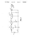
- FIG. 6 is a detailed circuit diagram of the battery circuit for the fluid shutoff system of FIG. 1.
- FIG. 1 shows in block diagram form an automatic fluid shutoff system 10 embodying principles of the present invention.
- the system may be installed on a conduit 12 for a house or building which is connected to a fluid supply source such as a pump or a city water supply.
- the system 10 comprises a flow sensor 14, a shutoff valve 16 connected to a valve motor 18, a control circuit 20 and a display monitor 22 that indicates present system conditions and has yellow, green and red lights.
- the circuit 20 includes a power conversion sub-circuit 24 connected to an AC power source 26 and including a battery power source 28.
- the power circuit supplies D.C. voltage to the motor and control circuit from either of the two alternative power sources.
- a switching means in the power circuit automatically produces power output from the battery source if for some reason the conventional AC power source is disabled.
- the control circuit 20 receives inputs from an occupant mode switch 30 on a control panel 31, as well as status inputs from the flow sensor and the motor.
- the control circuit 30 comprises a pin controllable counter 32 which includes a real time clock in combination with a buffered inverter 34 which includes 6 inverters two of which provide a bi-stable latch.
- the control circuit functions generally to close the valve 16 in the conduit 12 automatically when it determines that water has been flowing in the conduit 12 for a predetermined period of time.
- the flow sensor 14 provides a first signal indicative of the water flow in conduit 12 which is furnished through the buffered inverter 34 to the pin controllable counter 32 which has been preset by the occupant mode switch 30 to provide a second signal indicative of whether or not the building is monitored by a person.
- Switch 30 may be a simple two-position switch that is operated by the occupant of the building which provides an input to the pin controllable counter.
- the valve 16 is coupled to motor 18 which receives power from the power circuit 24. The motor is responsive to a third signal to open valve 18 and to a fourth signal to close the valve.
- the buffered inverter 34 is representative of the means for generating the third and fourth signals which are provided to valve motor 18 at selected times in response to the stored first and second signals respectively stored in the pin controllable counter 32. Using these inputs, the control circuit 20 generates output signals for opening and closing the valve 16 as described below in greater detail.
- the control circuit 20 also provides output signals to the display means 22 to energize a green, yellow and red light respectively to detect when the system is operating with no water flow (Green); when the system is sensing water flow (Yellow); and when the system has shut off external water supply to conduit 12 by means of valve 16 (Red).
- the flow sensor 14 in its preferred form is shown coupled to the shutoff valve 16.
- the sensor comprises a T-shaped housing 36 having a main tubular portion 38 and an upwardly projecting tubular portion 40.
- One end 42 of the main tubular portion is sized to fit around the conduit 12 from the water supply source and the opposite end 44 is adapted to couple directly with the valve 16, or if desired, with an extended section of conduit.
- the sensor 14 is shown directly adjacent to the valve 16 in FIG. 2, these components may be separated by conduit of any length, if desired.
- the T-shaped sensor housing 36 may be machined, cast or molded from any suitable metal or plastic material.
- a cylindrical insert housing 46 Situated within the upwardly projecting tubular portion 40 is a cylindrical insert housing 46 which is retained by a pair of set screws 48, as shown in FIG. 3. A groove at the lower end of the housing 46 retains a sealing 0-ring 50.
- the housing 46 has a central recess 47 that forms a circular bottom 49 of substantially uniform thickness.
- Extending below one side of the bottom and integral therewith is a downwardly projecting member 55 which has a relatively narrow slot or pocket 51 whose upper end is open within the recess. Retained within this pocket is a "Hall effect" sensor device 52 of a type that is commercially available. The main functional characteristic of this sensor device is that it will produce an output signal when it comes within a magnetic field of a certain strength.
- a stud portion 54 Extending at a right angle from the lower end of the projecting member 50 is a stud portion 54 which forms an axle means for a pivotal flapper 56.
- the flapper is an elongated relatively thin member of substantially constant width which extends downwardly into the space between opposite ends of the main tubular portion of the sensor housing. Near the upper end of the flapper is an integral tubular portion 57 which forms a bearing through which the axle stud portion 54 of the projecting member 50 extends with sufficient clearance to provide easy rotation.
- the flapper is retained on the stud portion 54 by a conventional snap ring 58 that fits on the end of the stud portion. As shown in FIG. 3, the flapper 56 has an enlarged portion 59 at its lower end to provide more area for water contact.
- transverse metal dowell pin 60 which serves as a counterweight to urge the flapper into an upright, vertical position when no flow of water is occurring through the sensor.
- a transverse cylindrical magnet 62 At the upper end of the flapper above the stud axle is a transverse cylindrical magnet 62. When the flapper is in its vertical, no-flow position, the magnet 62 is directly adjacent to the Hall effect sensor chip 52 thereby causing it to emit a no-flow signal to the control circuit 20.
- flapper 56 moves off the rest vertical position, as shown, in phantom in FIG. 2, and displaces magnet 62 which is immediately sensed by magnet sensing means 52.
- Magnet sensing means 52 then sends a first signal representative of fluid flow over to the buffered inverter 34 (shown in FIG. 1).
- the control circuit 20 evaluates such first signals by means of predetermined parameters such as flow duration, and whether the plumbing system is monitored or unmonitored, etc. as will be described later by reference to FIG. 5, the detailed circuit diagram of the control circuit 20 for the invention.
- the shutoff valve 16 as shown in FIG. 2, comprises a Tee-shaped housing 64 having a lower main section with aligned tubular inlet and outlet end portions 65 and 66 and a tubular boss portion 67 extending upwardly between them. Below the boss portion and between the end portions 65 and 66 is a compartment 68 within which is a rotatable ball 69. The ball is supported on its opposite sides for rotary movement within the compartment by a pair of spaced apart annular washers 70. Each washer has a curved inner surface 72 which is shaped to conform with the ball surface.
- a cylindrical passage 74 Extending diametrically through the ball is a cylindrical passage 74 whose axis is aligned within the axis of the housing end portions 65 and 66 when the valve is open, and is perpendicular to it in the same plane when the valve is closed.
- a stud member 76 Extending from the top side of the ball is a stud member 76 which is fixed to the lower end of a stem member 78 that is rotatable within a bore 79 within the boss portion 67 of the housing 64.
- the stem member has a clearance within the boss portion that provides low friction turning and it is sealed by an 0-ring 80 seated within a groove near the lower end of the stem.
- the motor assembly 18 which operates to turn the valve ball 68.
- the motor assembly is supported by a pair of posts 86 which are attached to and extend upwardly from a mounting plate 88. The latter is secured to the housing boss portion 67 by a machine screw 90.
- the motor assembly comprises a small DC motor 92 of any suitable commercially available type, whose output is provided through a reduction gear box 94 to an output shaft 96 which is drivingly connected to the upper end of the stem member 78.
- a cam member 98 is fixed to the upper end of the stem member and held in place by a snap ring 100.
- the cam member has curved camming surfaces 101 at its opposite diametral ends which are adapted to contact and depress a button switch 102 that is fixed to the mounting plate during 90° of rotation by the cam.
- the cam is positioned on the stem member so that the switch 102 is contacted and actuated for every 180° of rotation of the valve ball.
- the low power motor 92 operates always in one direction, only whenever it receives a turn-on signal, to rotate the valve ball 69 through 90° from either the open to close position or from the close to open position.
- the control circuit operates normally using low voltage (e.g. 9-12 volts) DC, derived from standard house power (110 VAC) but if house power is lost for some reason, the system 10 will operate using standby battery power (e.g. 9-12 volts).
- the sub-circuit 24 showing the alternative power arrangement is shown in FIG. 6.
- An input jack 104 is provided which can receive a plug-in end of wire from a conventional AC to DC rectifier unit 105, of the type commonly used for portable electronic devices, which may plug into a standard 110 volt house socket. The rectifier thus converts the 110 volts to 9-12 volts D.C. and supplies it to the jack 104.
- Voltage from the input jack is furnished to an input (V 1 side of a standard regulator 106 (MC7812C) which functions to eliminate any surges that may be caused by the AC power source.
- the output (V 0 ) of regulator 106 is connected through a first junction 107 and through a diode 108 to a second junction 109.
- the first junction provides an output V 1 and the second junction provides an output V s .
- the second junction is also connected through a diode 110 to the plus terminal of a battery 111 (e.g. 9 volts) whose negative side is connected to a ground lead 112.
- a third lead 113 from the second junction is connected through a capacitor 114 to ground, and a third lead 114 from the first junction 107 is connected to ground through a resistor 115 and a green LED 116 which provides a "power on indication".
- the green LED 116 will go out.
- V 1 and V s outputs from the power circuit are connected to various input terminals on the circuit.
- V 1 voltage is supplied at a main input terminal through a diode 121 to the yellow LED 120 and also through a diode 122 to a red LED 123.
- the V s voltage connections are separately connected through diodes 124 and 125 to the LED's 120 and 123 and also directly to the Hall effect sensor 14 through a junction 126.
- the functions of signal storing, processing and timing are provided by the CMOS oscillator and pin programmable counter 32 (IC 4541) which is used in conjunction with the hex-invertor 34 (IC 4049).
- the hex inverter 34 is an integrated circuit consisting of six CMOS inverting buffer gates shown at 127, 128, 129, 130, 131 and 132 respectively, two of which, 127 and 128, are used as a bistable latch 34 whose primary output at a terminal 119 can be set (raised high) by a momentary high on the diode 133 input, a momentary closure of a red flow switch shown at 134 or cleared CLR (reset to low) by a momentary low on the input of CMOS inverting buffer gate 127 through the inverting buffer gate 128, a diode 135 and a switch 136 to ground.
- the bistable latch comprised of inverters 127 and 128 also has a complementary output through a lead 137 which is the inverse of the primary output 119 located on buffer gate 128.
- the purpose of this bistable latch is to act as a memory hold to maintain a signal to a pair of motor drive transistors 138, 139 in the event the time-out period signal or the Set or Reset buttons 134 and 136 change the state of the bistable latch before the motor 18 is able to complete the one quarter turn of the valve 16 as previously described.
- Two more of these inverting buffer gates, 130 and 132, respectively are used to drive yellow and red status indicator LED's shown generally at 120 and 123.
- the remaining two CMOS buffer gates 131 and 129 serve to control the reset pin 6 of integrated circuit 32.
- the program timer 32 provides the set time out period, that is the time period of continuous water flow which can occur before a valve closing action is initiated. It has an on board clock oscillator whose frequency is determined by a pair of resistors 140 and 141 and a capacitor 142 connected to pins 1, 3 and 2 of counter 32. Pin Q of counter 32 provides the output of the internal logical counter chain.
- a pin 9 is grounded by a dual-in-line (DIP) switch 143 having four leads connected to ground. This sets the output normally low when the circuit counter is reset.
- a pin 10, grounded by the switch 143 sets a single cycle timing mode;
- a pin 5, grounded by the switch sets automatic power on reset; and
- a pin 13 provides a demonstration mode which is tied high by single incline package (SIP) resistor 144, sets a base divide module counter.
- a pin 12 is tied high by the SIP resistor and is connected to the occupant mode switch 30 in a lead 145 which, when open, selects a "short" interval in the counter 32 for situations where the house or building will be unoccupied and when grounded by closing switch 30, selects a "long” interval in the counter 32.
- the "short" time period may be as low as two minutes when the building is unoccupied, while the long time period may be more appropriately set for around two hours when the building is occupied.
- a pin 6 in the counter 32 provides a reset input and is high because there is no flow of water holding back the start of a timing cycle.
- a high reset can be the result of the momentary closure of the reset switch 136 introducing a low to CMOS inverting buffer gate 131 by a path through SIP resistor 144, a diode 146 and switch 176 to ground. This produces a high at pin 15 of CMOS inverting buffer gate 131 forward biasing a diode 147 to the reset pin 6 of the integrated circuit counter 32.
- a no flow sensor 14 condition at CMOS inverting buffer gate 129 produces a high at its output to charge a capacitor 148 CMOS eventually raising the voltage at the pin 6 of counter 32, which is thereby set high.
- the flow sensor 14 output indicated generally at junction 149 must be low, drawing a small current through SIP resistor 144, and the connecting inputs of inverting buffer gates 129 and 130 respectively are also low, causing their outputs to go high.
- the yellow LED 120 is off, indicating a no flow water condition.
- capacitor 148 is charged high through a resistor 150 raising the reset pin 6 of the integrated circuit counter 32 high.
- the Q output pin 8 of counter 32 is at a low (don't care) condition to the bistable latch 132 whose output at terminal 119 is low causing the input of inverting buffer gate 132 and a gate resistor 151 of the transistor 139 to also go low.
- a low on the input to inverting buffer gate 132 causes its output to go high and the red LED 123 to be off.
- a low on the gate resistor 151 of transistor 139 causes the latter to function as an open switch between a junction 152 and ground, and thus no motor current can flow to motor 18.
- Transistor 138 is the opposite of transistor 139 and functions as a closed switch to ground, but since the cam switch 102 path is open, no current can flow through a junction 153 to the motor 18. This results in the predominant steady state condition with no motor 18 or valve 16 change or action, i.e. water is available, the watchdog control circuit 20 is ready to time any flow period and to close the water valve 16 if the flow period exceeds the preset time out.
- the manual flow-on momentary push button (Green) switch 136 is open and since the bistable latch is already in the clear mode, switch 136 could be closed with no circuit change.
- the manual flow-off momentary push button 134 (Red) is open. When this button is pressed, a high charge on a capacitor 155 is applied to the input of inverting buffer gate 127 of the bistable latch 132 causing it to change the state of its output from the gate resistor 156 of transistor 138 and apply a high to a gate resistor 151 of transistor 139, causing the system to close the water valve 16 (FIG. 1) in the manner described later in this description.
- a high on the input of inverting buffer gate 132 causes its output to go low causing the red LED light 123 to indicate that a time out condition has occurred.
- a high on the gate resistor 151 of transistor 139 causes it to function as a closed switch between the junction 152 and ground, and thus motor current now begins to flow through the path input power jack 104 to a V s junction 158 to motor 18, through switch 102, junction 152, and transistor 139 to ground. This condition continues until the motor 18 causes a full one quarter turn of the water valve 18 and the associated cam switch 102 interrupts the above motor current to halt the rotation of the now closed water valve.
- the red LED light shown at 123 now indicates a closed water valve.
- the flow sensor 14 output at junction 149 must go low, drawing a small current through SIP resistor 144 and the connecting inputs of inverting buffer gates 129 and 130 respectively, causing their outputs to go high.
- the yellow LED light 120 is off, indicating a no flow water condition.
- capacitor 148 is charged high through resistor 150, raising the reset pin 6 of integrated circuit counter 32 high.
- the counter reset pin 6 active, its Q output is at a low (don't care) condition to the bistable latch 34 whose output pin 12 shown at 119 is still high including the input of the inverting buffer gate 132 and the gate resistor 151 of the transistor 139.
- This safety feature is the desired temporary condition in the event of a possible damaging household water leak.
- the red LED indicator 123 and closed water valve 16 will remain so locked until noticed by the occupant who can then restore water service by pressing the green reset button 136 on the control panel. The occupant is thereby cautioned to shut off all water facilities and perform a careful search for a plumbing leak.
- Pressing green switch 136 draws a small current through resistor 160 and diode 135 and lowers the input of inverting buffer gate 127 causing the bistable latch 34 to reverse its state. This lowers the primary output of inverting buffer gate 128 low connecting the gate resistor 151 of transistor 139 and also the input of inverting buffer gate 132, while raising high the complementary outputs of inverting buffer gates 127 and 128 respectively.
- a low on the input of inverting buffer gate 132 causes its output to go high and the red LED 123 to go off.
- a low on the gate resistor 151 of transistor 139 causes the transistor to behave as an open switch between the junction 152 and ground, and thus no motor current can flow.
- Transistor 138 is in the opposite state and behaves as a closed switch to ground, since the cam switch 102 path is also closed, and motor current begins to flow through the junction 158, motor 18, switch 102, junction 153 and transistor 138 to ground causing the water valve to rotate one quarter turn until the associated cam switch 102 interrupts the motor current to halt rotation of the now open water valve 18. This results again in the predominant steady state condition, with no motor or valve change or action, i.e. water is available, the watchdog control circuit 20 is ready to time any flow period, and close the water valve if the period exceeds the preset time out condition.
- battery operation is included to provide temporary leak or floodwatch protection in the event of a loss of house power.
- the system provides for a reduced indicator LED current drain while under battery operation.
- DC electrical energy is supplied by the 9 volt battery 111 to diode 110 to the system circuit positive source or node V s and no energy gets to the node V 1 . Consequently, the current path for both yellow and red LED's from the input V s must flow through the increased resistance provided by resistor 117 to the yellow LED 120 and through a resistor 164 to the red LED 123, resulting in less current being used by the two lamps.
- control circuit constructed according to the teachings of the invention and as depicted in the schematics of FIGS. 5 and 6, responds to preset operating parameters and external conditions according to the following conditions of operation:
- Flow detector “flapper” is in the vertical position signifying no water flow.
- the circuitry senses the presence of the magnet and turns on the Green light, signifying that the system is operating and that no water is flowing. This condition also signifies that the AC power is also operating.
- Flow detector “flapper” is not vertical, which signifies that water is flowing. Circuitry detects no magnetic presence and turns on the Yellow light. Both the Green and Yellow lights are “on” which means that the AC is on and that the system is operating and that water flow is detected.
- condition #11 has occurred, the homeowner cannot reopen the valve until a fresh power supply is introduced (either AC or new batteries).
- the system has two time-out periods, which are selectable by the homeowner depending on the status of the home. If the home is occupied, the longer (approximately 2 hours) time-out period should be selected. If the home is going to be vacant, the shorter (approximately 2 minutes) time-out period should be selected.
Abstract
Description
Claims (6)
Priority Applications (1)
| Application Number | Priority Date | Filing Date | Title |
|---|---|---|---|
| US07/535,124 US5038820A (en) | 1990-06-08 | 1990-06-08 | Automatic fluid shutoff system |
Applications Claiming Priority (1)
| Application Number | Priority Date | Filing Date | Title |
|---|---|---|---|
| US07/535,124 US5038820A (en) | 1990-06-08 | 1990-06-08 | Automatic fluid shutoff system |
Publications (1)
| Publication Number | Publication Date |
|---|---|
| US5038820A true US5038820A (en) | 1991-08-13 |
Family
ID=24132950
Family Applications (1)
| Application Number | Title | Priority Date | Filing Date |
|---|---|---|---|
| US07/535,124 Expired - Lifetime US5038820A (en) | 1990-06-08 | 1990-06-08 | Automatic fluid shutoff system |
Country Status (1)
| Country | Link |
|---|---|
| US (1) | US5038820A (en) |
Cited By (67)
| Publication number | Priority date | Publication date | Assignee | Title |
|---|---|---|---|---|
| US5287884A (en) * | 1992-07-24 | 1994-02-22 | Cohen Jeffrey D | Water flow monitoring system for determining the presence of leaks and stopping flow in plumbing pipes |
| US5409037A (en) * | 1994-06-06 | 1995-04-25 | Wheeler; Jaye F. | Automatic device for the detection and shutoff of excess water flow in pipes |
| US5464038A (en) * | 1994-08-11 | 1995-11-07 | Kruto; Donald | Fluid flow control system |
| US5503175A (en) * | 1994-12-22 | 1996-04-02 | Ravilious; Paul W. | Water safety system |
| US5771920A (en) * | 1997-08-04 | 1998-06-30 | Flologic, Inc. | Domestic water valve assembly |
| US5782263A (en) * | 1995-08-04 | 1998-07-21 | Gary A. Isaacson, Jr. | Flood control device |
| US5934302A (en) * | 1996-05-01 | 1999-08-10 | Nemelka; Mark S. | Control valve apparatus and method for regulating fluid flow in fluid-intake machines |
| US5960807A (en) * | 1998-05-05 | 1999-10-05 | Reyman; Mark | Vibration and flow actuated valve shutoff system |
| US5979493A (en) * | 1996-08-02 | 1999-11-09 | Gary A. Isaacson, Jr. | Flood control device |
| US6029693A (en) * | 1995-09-20 | 2000-02-29 | Kitz Corporation | Valve driving apparatus |
| US6105607A (en) * | 1998-06-15 | 2000-08-22 | Caise; Robert F. | Microprocessor controled water shut-off device |
| US6114823A (en) * | 1997-12-30 | 2000-09-05 | Agf Manufacturing, Inc. | Circuit and apparatus for sensing fluid flow |
| US6164319A (en) * | 1997-04-04 | 2000-12-26 | Cochran; David J. | Automatic shut-off device for a pipe |
| US6216727B1 (en) * | 1999-03-08 | 2001-04-17 | Flologic, Inc. | Water flow sensing device |
| US6246331B1 (en) | 1999-01-05 | 2001-06-12 | Agf Manufacturing, Inc. | Apparatus for sensing fluid flow and associated load control circuit |
| FR2806476A1 (en) * | 2000-03-16 | 2001-09-21 | Francois Danger | Control device for preventing e.g. accidents, explosions or spillages of gas or liquid in e.g. industry, counts duration of escaping gas or liquid to atmosphere |
| US6374846B1 (en) | 2001-01-19 | 2002-04-23 | Flologic, Inc. | System for excercising the control valve for a water shut-off valve |
| US6382252B1 (en) * | 1998-08-26 | 2002-05-07 | Eco-Logic (Uk) Emps Limited | Control unit for fluid control valves |
| US6396404B1 (en) | 1999-01-05 | 2002-05-28 | Agf Manufacturing, Inc. | Double check valve assembly for fire suppression system |
| US6401741B1 (en) * | 2000-11-07 | 2002-06-11 | Jimmy D. Cain | Excess flow shut-off valve |
| US6523562B2 (en) | 2000-11-08 | 2003-02-25 | Roger Harper | Plumbing flood control system |
| US6543471B1 (en) | 2002-06-18 | 2003-04-08 | James H. Carroll | Water heater fail safe apparatus |
| US20030196709A1 (en) * | 2002-04-23 | 2003-10-23 | Mendoza Michael J. | Compressed air flow controller |
| US6701951B1 (en) * | 1999-10-18 | 2004-03-09 | Don Lovis Drinkwater | Manual to electronic automatic valve conversion apparatus |
| US20040134545A1 (en) * | 2002-04-11 | 2004-07-15 | Ford Michael Brent | Method and system for controlling a household water supply incorporating motion-sensing for determining whether a house is occupied |
| US20040149947A1 (en) * | 2003-02-01 | 2004-08-05 | Benjamin Grill | Manually-opened and latchable with only residual magnetism, two-way two-position fluid control valve assembly and methods of operation |
| US20040155784A1 (en) * | 2002-08-12 | 2004-08-12 | Candela Paul Joseph | Water leak mitigation system |
| WO2004072602A1 (en) * | 2003-02-17 | 2004-08-26 | Frederick Dennis Bowerman | A valve arrangement |
| US6812848B2 (en) * | 2002-08-12 | 2004-11-02 | Flo-Guard Water Leak Mitigation Systems, Llc | Water leak mitigation system |
| US20040226614A1 (en) * | 2003-05-13 | 2004-11-18 | Lane James Raymond | Catastrophe avoidance system and method |
| US6880574B1 (en) * | 2003-05-01 | 2005-04-19 | Lou Porto | Automated water disabling valve for an appliance |
| US20050126635A1 (en) * | 2003-12-16 | 2005-06-16 | Sylvan Addink | Smart flow anomaly detector |
| US20060260691A1 (en) * | 2005-05-20 | 2006-11-23 | Davidoff John A | Systems and methods for detecting and preventing fluid leaks |
| US20080054209A1 (en) * | 2006-08-29 | 2008-03-06 | Custom Controls, Llc. | Manual to automatic valve conversion device |
| US20080092965A1 (en) * | 2006-10-24 | 2008-04-24 | Ron Hymes | Automatic smart watering apparatus |
| US7403839B1 (en) | 2006-12-19 | 2008-07-22 | Joshua Kaplan | Water shut-off system |
| US20080252471A1 (en) * | 2007-04-12 | 2008-10-16 | Michael Brent Ford | Method and system for reliably detecting structure and water system leaks |
| US20080251131A1 (en) * | 2007-04-12 | 2008-10-16 | Michael Brent Ford | Method and system for detecting water system leaks |
| US20100206386A1 (en) * | 2009-02-19 | 2010-08-19 | Crucs Holdings, Llc | Apparatus and method for automatically disabling utilities |
| US20100258204A1 (en) * | 2009-04-14 | 2010-10-14 | Enolgas Bonomi S.P.A. | Device for Detecting Leaks of Fluids |
| US20100307600A1 (en) * | 2009-02-19 | 2010-12-09 | Crucs Holdings, Llc | Apparatus and method for automatically disabling utilities |
| US20110073189A1 (en) * | 2009-09-30 | 2011-03-31 | Elbert James C | Water shut off with flow sensor emergency shut down |
| US20110209770A1 (en) * | 2008-08-25 | 2011-09-01 | H2O Organiser Pty. Ltd. | Control system and method for water supply |
| US20110248199A1 (en) * | 2010-04-09 | 2011-10-13 | Konovalski Nicholas K | Electronic water main shutoff |
| US20110247711A1 (en) * | 2008-12-19 | 2011-10-13 | Panasonic Corporation | Gas shutoff device |
| US8100141B2 (en) | 2010-05-27 | 2012-01-24 | Slupecki Raymond H | Water supply control assembly with automatic shut-off and duty cycle reset |
| US8931755B2 (en) | 2006-08-29 | 2015-01-13 | Custom Controls, Llc | Manual to automatic valve conversion device |
| US9016662B2 (en) | 2006-08-29 | 2015-04-28 | Custom Controls, Llc | Efficient manual to automatic valve conversion device |
| US9066496B2 (en) | 2006-10-24 | 2015-06-30 | Ron Hymes | Automatic smart watering apparatus |
| ES2567207A1 (en) * | 2015-09-30 | 2016-04-20 | Juan FERNÁNDEZ ROS | Abnormal water consumption safety detector (Machine-translation by Google Translate, not legally binding) |
| US20160109124A1 (en) * | 2014-10-16 | 2016-04-21 | Andrew Crane | Fuel metering device |
| US20160130024A1 (en) * | 2013-06-12 | 2016-05-12 | Gea Food Solutions Germany Gmbh | Packaging machine having a sealing means |
| US20160356026A1 (en) * | 2015-06-03 | 2016-12-08 | Robertshaw Controls Company | Rf-signal-emitting valve for flow monitoring and leak detection |
| US20170016214A1 (en) * | 2014-03-12 | 2017-01-19 | Aqua - Rimat Ltd. | A fluid flow system and method |
| US20170044744A1 (en) * | 2015-08-13 | 2017-02-16 | William Duke Everhart | Water system leak detection |
| US20170167907A1 (en) * | 2015-12-14 | 2017-06-15 | Charles A. Hair | Fluid regulation system |
| US20170228999A1 (en) * | 2016-02-04 | 2017-08-10 | Haws Corporation | Integrated water detection sensor |
| US9874882B2 (en) | 2006-10-24 | 2018-01-23 | Ron Hymes | Automatic smart watering apparatus |
| US9916748B1 (en) | 2017-04-25 | 2018-03-13 | Robert D. Yadvish | Talking water tank minder |
| US20180291594A1 (en) * | 2014-08-14 | 2018-10-11 | Reliance Worldwide Corporation | Methods and apparatus for fluid flow monitoring and leak detection |
| US20180299028A1 (en) * | 2015-10-12 | 2018-10-18 | Elbi International S.P.A. | Valve assembly with associated measurement device |
| US10533307B2 (en) | 2014-05-11 | 2020-01-14 | Wint - Wi Ltd. | Fluid governing system |
| US20200056707A1 (en) * | 2018-08-14 | 2020-02-20 | Automatic Switch Company | Smart pinch valve |
| US10775213B2 (en) | 2014-08-14 | 2020-09-15 | Reliance Worldwide Corporation | Devices and system for channeling and automatic monitoring of fluid flow in fluid distribution systems |
| US11105705B1 (en) * | 2017-03-31 | 2021-08-31 | Leaksentinel Inc. | Non-invasive, independently powered leak detector and valve shut-off apparatus |
| US11191437B2 (en) * | 2014-08-11 | 2021-12-07 | Murata Manufacturing Co., Ltd. | Fluid control device |
| US11513025B1 (en) * | 2018-03-21 | 2022-11-29 | Marc Warsowe | Leak detection systems |
Citations (5)
| Publication number | Priority date | Publication date | Assignee | Title |
|---|---|---|---|---|
| US2037575A (en) * | 1932-09-16 | 1936-04-14 | William R Hamilton | Alarm device for sprinkler systems |
| US3085432A (en) * | 1960-08-24 | 1963-04-16 | Fred Arnold Chauncey | Flow indicator |
| US4249563A (en) * | 1979-10-17 | 1981-02-10 | The Protectoseal Company | Manifold for replacing relief valves |
| US4898036A (en) * | 1987-01-21 | 1990-02-06 | Span Instruments, Inc. | Flow responsive transmitter and indicator |
| US4911200A (en) * | 1988-11-25 | 1990-03-27 | Ben Arie Reuben | Control of excessive fluid flow |
-
1990
- 1990-06-08 US US07/535,124 patent/US5038820A/en not_active Expired - Lifetime
Patent Citations (5)
| Publication number | Priority date | Publication date | Assignee | Title |
|---|---|---|---|---|
| US2037575A (en) * | 1932-09-16 | 1936-04-14 | William R Hamilton | Alarm device for sprinkler systems |
| US3085432A (en) * | 1960-08-24 | 1963-04-16 | Fred Arnold Chauncey | Flow indicator |
| US4249563A (en) * | 1979-10-17 | 1981-02-10 | The Protectoseal Company | Manifold for replacing relief valves |
| US4898036A (en) * | 1987-01-21 | 1990-02-06 | Span Instruments, Inc. | Flow responsive transmitter and indicator |
| US4911200A (en) * | 1988-11-25 | 1990-03-27 | Ben Arie Reuben | Control of excessive fluid flow |
Cited By (88)
| Publication number | Priority date | Publication date | Assignee | Title |
|---|---|---|---|---|
| US5287884A (en) * | 1992-07-24 | 1994-02-22 | Cohen Jeffrey D | Water flow monitoring system for determining the presence of leaks and stopping flow in plumbing pipes |
| US5409037A (en) * | 1994-06-06 | 1995-04-25 | Wheeler; Jaye F. | Automatic device for the detection and shutoff of excess water flow in pipes |
| US5464038A (en) * | 1994-08-11 | 1995-11-07 | Kruto; Donald | Fluid flow control system |
| US5503175A (en) * | 1994-12-22 | 1996-04-02 | Ravilious; Paul W. | Water safety system |
| US6119720A (en) * | 1995-08-04 | 2000-09-19 | Gary A. Isaacson, Jr. | Flood control device |
| US5782263A (en) * | 1995-08-04 | 1998-07-21 | Gary A. Isaacson, Jr. | Flood control device |
| US6029693A (en) * | 1995-09-20 | 2000-02-29 | Kitz Corporation | Valve driving apparatus |
| US5934302A (en) * | 1996-05-01 | 1999-08-10 | Nemelka; Mark S. | Control valve apparatus and method for regulating fluid flow in fluid-intake machines |
| US5979493A (en) * | 1996-08-02 | 1999-11-09 | Gary A. Isaacson, Jr. | Flood control device |
| US6164319A (en) * | 1997-04-04 | 2000-12-26 | Cochran; David J. | Automatic shut-off device for a pipe |
| US5771920A (en) * | 1997-08-04 | 1998-06-30 | Flologic, Inc. | Domestic water valve assembly |
| US6114823A (en) * | 1997-12-30 | 2000-09-05 | Agf Manufacturing, Inc. | Circuit and apparatus for sensing fluid flow |
| WO1999057469A1 (en) * | 1998-05-05 | 1999-11-11 | Mark Reyman | Vibration and flow actuated valve shutoff system |
| US6694997B2 (en) | 1998-05-05 | 2004-02-24 | Mark Reyman | Enhanced and remote meter reading with vibration actuated valve |
| US5960807A (en) * | 1998-05-05 | 1999-10-05 | Reyman; Mark | Vibration and flow actuated valve shutoff system |
| US6105607A (en) * | 1998-06-15 | 2000-08-22 | Caise; Robert F. | Microprocessor controled water shut-off device |
| US6382252B1 (en) * | 1998-08-26 | 2002-05-07 | Eco-Logic (Uk) Emps Limited | Control unit for fluid control valves |
| US6246331B1 (en) | 1999-01-05 | 2001-06-12 | Agf Manufacturing, Inc. | Apparatus for sensing fluid flow and associated load control circuit |
| US6246333B1 (en) | 1999-01-05 | 2001-06-12 | Agf Manufacturing, Inc. | Apparatus for sensing fluid flow and associated load control circuit |
| US6396404B1 (en) | 1999-01-05 | 2002-05-28 | Agf Manufacturing, Inc. | Double check valve assembly for fire suppression system |
| US6216727B1 (en) * | 1999-03-08 | 2001-04-17 | Flologic, Inc. | Water flow sensing device |
| US6701951B1 (en) * | 1999-10-18 | 2004-03-09 | Don Lovis Drinkwater | Manual to electronic automatic valve conversion apparatus |
| FR2806476A1 (en) * | 2000-03-16 | 2001-09-21 | Francois Danger | Control device for preventing e.g. accidents, explosions or spillages of gas or liquid in e.g. industry, counts duration of escaping gas or liquid to atmosphere |
| US6401741B1 (en) * | 2000-11-07 | 2002-06-11 | Jimmy D. Cain | Excess flow shut-off valve |
| US6523562B2 (en) | 2000-11-08 | 2003-02-25 | Roger Harper | Plumbing flood control system |
| US6374846B1 (en) | 2001-01-19 | 2002-04-23 | Flologic, Inc. | System for excercising the control valve for a water shut-off valve |
| US6892746B2 (en) * | 2002-04-11 | 2005-05-17 | Michael Brent Ford | Method and system for controlling a household water supply incorporating motion-sensing for determining whether a house is occupied |
| US20040134545A1 (en) * | 2002-04-11 | 2004-07-15 | Ford Michael Brent | Method and system for controlling a household water supply incorporating motion-sensing for determining whether a house is occupied |
| US20030196709A1 (en) * | 2002-04-23 | 2003-10-23 | Mendoza Michael J. | Compressed air flow controller |
| US6986361B2 (en) * | 2002-04-23 | 2006-01-17 | Mendoza Michael J | Compressed air flow controller |
| US6543471B1 (en) | 2002-06-18 | 2003-04-08 | James H. Carroll | Water heater fail safe apparatus |
| US7030767B2 (en) | 2002-08-12 | 2006-04-18 | Flo-Guard Water Leak Mitigation Systems, L.L.C. | Water leak mitigation system |
| US20040155784A1 (en) * | 2002-08-12 | 2004-08-12 | Candela Paul Joseph | Water leak mitigation system |
| US6812848B2 (en) * | 2002-08-12 | 2004-11-02 | Flo-Guard Water Leak Mitigation Systems, Llc | Water leak mitigation system |
| US20040149947A1 (en) * | 2003-02-01 | 2004-08-05 | Benjamin Grill | Manually-opened and latchable with only residual magnetism, two-way two-position fluid control valve assembly and methods of operation |
| US6820856B2 (en) | 2003-02-01 | 2004-11-23 | Sturman Bg, Llc | Manually-opened and latchable with only residual magnetism, two-way two-position fluid control valve assembly and methods of operation |
| WO2004072602A1 (en) * | 2003-02-17 | 2004-08-26 | Frederick Dennis Bowerman | A valve arrangement |
| US6880574B1 (en) * | 2003-05-01 | 2005-04-19 | Lou Porto | Automated water disabling valve for an appliance |
| US20040226614A1 (en) * | 2003-05-13 | 2004-11-18 | Lane James Raymond | Catastrophe avoidance system and method |
| US20050126635A1 (en) * | 2003-12-16 | 2005-06-16 | Sylvan Addink | Smart flow anomaly detector |
| US20060260691A1 (en) * | 2005-05-20 | 2006-11-23 | Davidoff John A | Systems and methods for detecting and preventing fluid leaks |
| US20080054209A1 (en) * | 2006-08-29 | 2008-03-06 | Custom Controls, Llc. | Manual to automatic valve conversion device |
| US8256742B2 (en) | 2006-08-29 | 2012-09-04 | Custom Controls Llc | Manual to automatic valve conversion device |
| US9016662B2 (en) | 2006-08-29 | 2015-04-28 | Custom Controls, Llc | Efficient manual to automatic valve conversion device |
| US8931755B2 (en) | 2006-08-29 | 2015-01-13 | Custom Controls, Llc | Manual to automatic valve conversion device |
| US20080092965A1 (en) * | 2006-10-24 | 2008-04-24 | Ron Hymes | Automatic smart watering apparatus |
| US9874882B2 (en) | 2006-10-24 | 2018-01-23 | Ron Hymes | Automatic smart watering apparatus |
| US9066496B2 (en) | 2006-10-24 | 2015-06-30 | Ron Hymes | Automatic smart watering apparatus |
| US7403839B1 (en) | 2006-12-19 | 2008-07-22 | Joshua Kaplan | Water shut-off system |
| US20080252471A1 (en) * | 2007-04-12 | 2008-10-16 | Michael Brent Ford | Method and system for reliably detecting structure and water system leaks |
| US8667978B2 (en) | 2007-04-12 | 2014-03-11 | Michael Brent Ford | Method and system for detecting water system leaks |
| US20080251131A1 (en) * | 2007-04-12 | 2008-10-16 | Michael Brent Ford | Method and system for detecting water system leaks |
| US8844835B2 (en) | 2007-04-12 | 2014-09-30 | Michael Brent Ford | Method and system for reliably detecting structure and water system leaks |
| US20110209770A1 (en) * | 2008-08-25 | 2011-09-01 | H2O Organiser Pty. Ltd. | Control system and method for water supply |
| US8393352B2 (en) * | 2008-08-25 | 2013-03-12 | H2O Organiser Pty Ltd | Control system and method for water supply |
| US8522815B2 (en) * | 2008-12-19 | 2013-09-03 | Panasonic Corporation | Gas shutoff device |
| US20110247711A1 (en) * | 2008-12-19 | 2011-10-13 | Panasonic Corporation | Gas shutoff device |
| US20100307600A1 (en) * | 2009-02-19 | 2010-12-09 | Crucs Holdings, Llc | Apparatus and method for automatically disabling utilities |
| US20100206386A1 (en) * | 2009-02-19 | 2010-08-19 | Crucs Holdings, Llc | Apparatus and method for automatically disabling utilities |
| US20100258204A1 (en) * | 2009-04-14 | 2010-10-14 | Enolgas Bonomi S.P.A. | Device for Detecting Leaks of Fluids |
| US20110073189A1 (en) * | 2009-09-30 | 2011-03-31 | Elbert James C | Water shut off with flow sensor emergency shut down |
| US20110248199A1 (en) * | 2010-04-09 | 2011-10-13 | Konovalski Nicholas K | Electronic water main shutoff |
| US8100141B2 (en) | 2010-05-27 | 2012-01-24 | Slupecki Raymond H | Water supply control assembly with automatic shut-off and duty cycle reset |
| US20160130024A1 (en) * | 2013-06-12 | 2016-05-12 | Gea Food Solutions Germany Gmbh | Packaging machine having a sealing means |
| US20170016214A1 (en) * | 2014-03-12 | 2017-01-19 | Aqua - Rimat Ltd. | A fluid flow system and method |
| US10309082B2 (en) * | 2014-03-12 | 2019-06-04 | Wint-Wi Ltd. | Fluid flow monitoring, verification and control system and method |
| US10533307B2 (en) | 2014-05-11 | 2020-01-14 | Wint - Wi Ltd. | Fluid governing system |
| US11191437B2 (en) * | 2014-08-11 | 2021-12-07 | Murata Manufacturing Co., Ltd. | Fluid control device |
| US10775213B2 (en) | 2014-08-14 | 2020-09-15 | Reliance Worldwide Corporation | Devices and system for channeling and automatic monitoring of fluid flow in fluid distribution systems |
| US10969261B2 (en) | 2014-08-14 | 2021-04-06 | Reliance Worldwide Corporation | Devices and system for channeling and automatic monitoring of fluid flow in fluid distribution systems |
| US10870970B2 (en) | 2014-08-14 | 2020-12-22 | Reliance Worldwide Corporation | Methods and apparatus for fluid flow monitoring and leak detection |
| US20180291594A1 (en) * | 2014-08-14 | 2018-10-11 | Reliance Worldwide Corporation | Methods and apparatus for fluid flow monitoring and leak detection |
| US10865546B2 (en) | 2014-08-14 | 2020-12-15 | Reliance Worldwide Corporation | Methods and apparatus for fluid flow monitoring and leak detection |
| US10837160B2 (en) * | 2014-08-14 | 2020-11-17 | Reliance Worldwide Corporation | Methods and apparatus for fluid flow monitoring and leak detection |
| US20160109124A1 (en) * | 2014-10-16 | 2016-04-21 | Andrew Crane | Fuel metering device |
| US20160356026A1 (en) * | 2015-06-03 | 2016-12-08 | Robertshaw Controls Company | Rf-signal-emitting valve for flow monitoring and leak detection |
| US9834911B2 (en) * | 2015-08-13 | 2017-12-05 | William Duke Everhart | Water system leak detection |
| US20170044744A1 (en) * | 2015-08-13 | 2017-02-16 | William Duke Everhart | Water system leak detection |
| ES2567207A1 (en) * | 2015-09-30 | 2016-04-20 | Juan FERNÁNDEZ ROS | Abnormal water consumption safety detector (Machine-translation by Google Translate, not legally binding) |
| US10508753B2 (en) * | 2015-10-12 | 2019-12-17 | Elbi International Spa | Valve assembly with associated measurement device |
| US20180299028A1 (en) * | 2015-10-12 | 2018-10-18 | Elbi International S.P.A. | Valve assembly with associated measurement device |
| US20170167907A1 (en) * | 2015-12-14 | 2017-06-15 | Charles A. Hair | Fluid regulation system |
| US20170228999A1 (en) * | 2016-02-04 | 2017-08-10 | Haws Corporation | Integrated water detection sensor |
| US11105705B1 (en) * | 2017-03-31 | 2021-08-31 | Leaksentinel Inc. | Non-invasive, independently powered leak detector and valve shut-off apparatus |
| US9916748B1 (en) | 2017-04-25 | 2018-03-13 | Robert D. Yadvish | Talking water tank minder |
| US11513025B1 (en) * | 2018-03-21 | 2022-11-29 | Marc Warsowe | Leak detection systems |
| US20200056707A1 (en) * | 2018-08-14 | 2020-02-20 | Automatic Switch Company | Smart pinch valve |
| US11131398B2 (en) * | 2018-08-14 | 2021-09-28 | Automatic Switch Company | Smart pinch valve |
Similar Documents
| Publication | Publication Date | Title |
|---|---|---|
| US5038820A (en) | Automatic fluid shutoff system | |
| US7549435B2 (en) | Systems and methods for detecting and correcting a leak | |
| US6237618B1 (en) | System and method for controlling the unwanted flow of water through a water supply line | |
| US6691724B2 (en) | Method and system for controlling a household water supply | |
| US5638847A (en) | Temperature sensitive water supply shut-off system | |
| US5251653A (en) | Control system for automatic fluid shut-off | |
| US6543479B2 (en) | Water monitoring system | |
| US5782263A (en) | Flood control device | |
| US5503175A (en) | Water safety system | |
| US20030066340A1 (en) | Conductive fluid leak detection system & automatic shut off valve | |
| US6105607A (en) | Microprocessor controled water shut-off device | |
| US7779852B2 (en) | Water conservation safety shut-off valve | |
| US6246331B1 (en) | Apparatus for sensing fluid flow and associated load control circuit | |
| US5402815A (en) | Temperature sensitive water supply shut-off system | |
| US9297467B1 (en) | Fluid leak detector apparatus | |
| US20020008627A1 (en) | Water leak detection and correction device | |
| US8689829B2 (en) | Fluid flow monitor | |
| US20150323412A1 (en) | Toilet water damage protection kit and method | |
| WO1986002431A1 (en) | Apparatus for shutting off gas | |
| US20160002842A1 (en) | Flood prevention systems for appliances | |
| CA2079028A1 (en) | Automatic shutoff valve | |
| US20040226614A1 (en) | Catastrophe avoidance system and method | |
| US5340281A (en) | Protective device for a water-pump apparatus | |
| CN201348074Y (en) | Overflow protector for kitchen and bathroom | |
| WO2014137650A1 (en) | Flood prevention systems for appliances |
Legal Events
| Date | Code | Title | Description |
|---|---|---|---|
| AS | Assignment |
Owner name: PHILIP L. AMES, NEVADA Free format text: ASSIGNMENT OF ASSIGNORS INTEREST.;ASSIGNORS:SCHULZ, RAINER R.;SCHULZ, RAINER R.;REEL/FRAME:005331/0818 Effective date: 19900606 |
|
| FPAY | Fee payment |
Year of fee payment: 4 |
|
| REMI | Maintenance fee reminder mailed | ||
| FP | Lapsed due to failure to pay maintenance fee |
Effective date: 19990813 |
|
| FEPP | Fee payment procedure |
Free format text: PETITION RELATED TO MAINTENANCE FEES FILED (ORIGINAL EVENT CODE: PMFP); ENTITY STATUS OF PATENT OWNER: SMALL ENTITY |
|
| FEPP | Fee payment procedure |
Free format text: PETITION RELATED TO MAINTENANCE FEES DENIED/DISMISSED (ORIGINAL EVENT CODE: PMFD); ENTITY STATUS OF PATENT OWNER: SMALL ENTITY |
|
| FEPP | Fee payment procedure |
Free format text: PETITION RELATED TO MAINTENANCE FEES GRANTED (ORIGINAL EVENT CODE: PMFG); ENTITY STATUS OF PATENT OWNER: SMALL ENTITY |
|
| FPAY | Fee payment |
Year of fee payment: 8 |
|
| SULP | Surcharge for late payment | ||
| FPAY | Fee payment |
Year of fee payment: 8 |
|
| SULP | Surcharge for late payment | ||
| STCF | Information on status: patent grant |
Free format text: PATENTED CASE |
|
| AS | Assignment |
Owner name: SAWKA, CRAIG S, MICHIGAN Free format text: ASSIGNMENT OF ASSIGNORS INTEREST;ASSIGNOR:AMES, PHILIP L.;REEL/FRAME:011089/0576 Effective date: 20000801 |
|
| PRDP | Patent reinstated due to the acceptance of a late maintenance fee |
Effective date: 20000804 |
|
| REIN | Reinstatement after maintenance fee payment confirmed | ||
| FP | Lapsed due to failure to pay maintenance fee |
Effective date: 20030813 |
|
| FEPP | Fee payment procedure |
Free format text: PETITION RELATED TO MAINTENANCE FEES FILED (ORIGINAL EVENT CODE: PMFP); ENTITY STATUS OF PATENT OWNER: SMALL ENTITY |
|
| AS | Assignment |
Owner name: ROMAN, MR. CESAR, MICHIGAN Free format text: ASSIGNMENT OF ASSIGNORS INTEREST;ASSIGNOR:SAWKA, MR. CRAIG S.;REEL/FRAME:015386/0975 Effective date: 20041126 |
|
| FEPP | Fee payment procedure |
Free format text: PETITION RELATED TO MAINTENANCE FEES GRANTED (ORIGINAL EVENT CODE: PMFG); ENTITY STATUS OF PATENT OWNER: SMALL ENTITY |
|
| FPAY | Fee payment |
Year of fee payment: 12 |
|
| SULP | Surcharge for late payment | ||
| PRDP | Patent reinstated due to the acceptance of a late maintenance fee |
Effective date: 20050131 |