US5046151A - Magnetic bearing device - Google Patents
Magnetic bearing device Download PDFInfo
- Publication number
- US5046151A US5046151A US07/549,983 US54998390A US5046151A US 5046151 A US5046151 A US 5046151A US 54998390 A US54998390 A US 54998390A US 5046151 A US5046151 A US 5046151A
- Authority
- US
- United States
- Prior art keywords
- control
- rotor
- current
- gain
- clearance
- Prior art date
- Legal status (The legal status is an assumption and is not a legal conclusion. Google has not performed a legal analysis and makes no representation as to the accuracy of the status listed.)
- Expired - Fee Related
Links
- 238000010586 diagram Methods 0.000 description 6
- 238000010276 construction Methods 0.000 description 3
- 238000006073 displacement reaction Methods 0.000 description 3
- BGPVFRJUHWVFKM-UHFFFAOYSA-N N1=C2C=CC=CC2=[N+]([O-])C1(CC1)CCC21N=C1C=CC=CC1=[N+]2[O-] Chemical compound N1=C2C=CC=CC2=[N+]([O-])C1(CC1)CCC21N=C1C=CC=CC1=[N+]2[O-] BGPVFRJUHWVFKM-UHFFFAOYSA-N 0.000 description 2
- 230000000694 effects Effects 0.000 description 1
- 230000010355 oscillation Effects 0.000 description 1
Images


Classifications
-
- F—MECHANICAL ENGINEERING; LIGHTING; HEATING; WEAPONS; BLASTING
- F16—ENGINEERING ELEMENTS AND UNITS; GENERAL MEASURES FOR PRODUCING AND MAINTAINING EFFECTIVE FUNCTIONING OF MACHINES OR INSTALLATIONS; THERMAL INSULATION IN GENERAL
- F16C—SHAFTS; FLEXIBLE SHAFTS; ELEMENTS OR CRANKSHAFT MECHANISMS; ROTARY BODIES OTHER THAN GEARING ELEMENTS; BEARINGS
- F16C32/00—Bearings not otherwise provided for
- F16C32/04—Bearings not otherwise provided for using magnetic or electric supporting means
- F16C32/0406—Magnetic bearings
- F16C32/044—Active magnetic bearings
- F16C32/0444—Details of devices to control the actuation of the electromagnets
Definitions
- This invention relates to a magnetic bearing device.
- FIG. 5 shows an example of known magnetic bearing devices conventionally used, and in which reference numeral 1 indicates a rotor to which an armature disk 2 is rotatably attached.
- a pair of bearing elements 3, 3 are disposed at positions on opposite sides in the axial direction putting the armature disk 2 therebetween.
- Each of the bearing elements 3, 3 comprises a pair of pole pieces 5, 6 attached to two pole faces of a premanent magnet 4.
- Each of the pole pieces 5, 6 comprises a part extending in parallel to the armature disk 2 and a top end part extending from the mentioned part to the position adjacent the armature disk 2.
- a control coil 7 is disposed at a position nearer to the top end part than the permanent magnet 4 between the mentioned pair of pole pieces 5, 6.
- a sensor coil 8 is disposed at a position nearer to the top end part than the control coil 7.
- the sensor coil 8 is wound in the same direction as the mentioned control coil 7, such that a bridge is formed between a pair of upper and lower sensor coils 8, 8 so as to differentially output variations of distance between the coil 8 and the armature disk 2.
- the known magnetic bearing device of the above construction is controlled with a control current of the control coil 7 in the following manner.
- control current I
- displacement of the armature disk 2 is x
- weight of the rotor 1 is mg
- This invention was made to solve the above-discussed problem and has an object of providing a magnetic bearing device in which small control current is satisfiable yet preventing from the disadvantage of enlargement of unstable region.
- the magnetic bearing device of this invention comprises a control coil which supports a rotor in a vertical direction; and current control means which increase the control current according to an increase in the clearance between the control coil and the rotor.
- the current control means includes gain control means which controls the control current with a larger gain when the clearance between the control coil and the rotor is less than a certain distance, and with a smaller gain when the clearance between the control coil and the rotor is more than that distance.
- the mentioned current control means includes a frequency response means which suspends control with the mentioned gain control means in response to the high rotary frequency of the rotor, while controlling the control current with almost a constant gain over the full length of the controllable clearance.
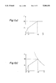
- FIGS. 1 (a) and (b) are explanatory diagrams each showing an example of the control characteristics of the magnetic bearing device as an embodiment according to this invention
- FIG. 2 is an explanatory diagram showing the timing for inserting the soft limiter used in the above embodiment
- FIG. 3 is a block diagram of an example of the control circuit adopted in the above embodiment
- FIG. 4 is an explanatory diagram showing a relation between frequency and gain obtained in the embodiment
- FIG. 5 is a sectional view of an example of construction of the magnetic bearing device in the prior art
- FIG. 6 is an explanatory diagram of a model showing the control characteristics in the magnetic bearing device shown in FIG. 5;
- FIGS. 7(a) and (b) are explanatory diagrams showing control characteristic in the prior art
- control current be reduced in the region of 0 ⁇ X ⁇ X 1 when balancing weight of the rotor 1 and the magnetic attraction of the control coil 7; while the gain k is returned to a normal small value in the region of X 1 ⁇ X ⁇ X 2 to enlarge the stable region of 0 ⁇ X ⁇ X 2 .
- a soft limiter is inserted in the control circuit to reduce the gain k at the voltage V, corresponding to the control current I, of the control coil 7 as shown in FIG. 2.
- FIG. 3 a control circuit as shown in FIG. 3 is employed.
- reference numeral 11 indicates an output circuit of the sensor coil 8
- numeral 12 indicates a compensating circuit
- numeral 13 indicates a soft limiter (gain control means)
- numeral 14 indicates a low frequency pass filter (frequency response control means)
- numeral 15 indicates an adder
- numeral 16 indicates a control coil drive circuit, respectively.
- This invention can be preferably applied to a magnetic bearing device of any constitution including the one shown in FIG. 5 or other.
Abstract
This invention discloses a magnetic bearing device having a control coil which supports a rotor in a vertical direction and a current controller which increases control current according to an increase in the clearance between the control coil and the rotor. The current controller includes a gain controller which controls the control current with a larger gain when clearance between the control coil and the rotor is less than a certain distance, and with a smaller gain when clearance between the control coil and the rotor is more than that distance.
Description
This is a continuation of application Ser. No. 383,788, filed July 24, 1989, now abandoned.
1. Industrial field
This invention relates to a magnetic bearing device.
2. Prior art
FIG. 5 shows an example of known magnetic bearing devices conventionally used, and in which reference numeral 1 indicates a rotor to which an armature disk 2 is rotatably attached. A pair of bearing elements 3, 3 are disposed at positions on opposite sides in the axial direction putting the armature disk 2 therebetween. Each of the bearing elements 3, 3 comprises a pair of pole pieces 5, 6 attached to two pole faces of a premanent magnet 4. Each of the pole pieces 5, 6 comprises a part extending in parallel to the armature disk 2 and a top end part extending from the mentioned part to the position adjacent the armature disk 2. A control coil 7 is disposed at a position nearer to the top end part than the permanent magnet 4 between the mentioned pair of pole pieces 5, 6. A sensor coil 8 is disposed at a position nearer to the top end part than the control coil 7. The sensor coil 8 is wound in the same direction as the mentioned control coil 7, such that a bridge is formed between a pair of upper and lower sensor coils 8, 8 so as to differentially output variations of distance between the coil 8 and the armature disk 2.
The known magnetic bearing device of the above construction is controlled with a control current of the control coil 7 in the following manner. For carrying out a simple control as shown in FIG. 6, supposing that control current is I, displacement of the armature disk 2 is x and weight of the rotor 1 is mg, the force acting on the armature disk 2 is expressed as follows:
F=a·I.sup.2 /x (1)
(where "a" is a proportional constant)
Accordingly, the condition to be F=mg is expressed as follows: ##EQU1## This means that the current I required in the control coil 7 varies according to the position x where magnetic attraction of the control coil 7 and weight of the rotor 1 are balanced.
Accordingly, the control current I is controlled so as to be I=k·x in the prior art. This is rewritten as x=I/k, and when substituting this expression for x in the above expression (2), a following expression (3) is obtained:
I=mg/a·k (3)
It is obviously understood from tha above expression (3) that the rotor 1 can be magnetically supported by a smaller current when establishing the gain k to be larger.
Thus, it seems desirable that the gain k for establishing the control current I be as large as possible.
When establishing the gain k to be as large as possible, however, there arises the serious disadvantage of narrowing the stable region of the rotor 1 with increased gain k. More specifically, establishing a maximum allowable current of the power supply for control current as I, magnetic attraction of the control coil 7 is lowered in the region of x>Io /k as shown in FIGS. 7(a) and (b), which results in unstable magnetic support.
This invention was made to solve the above-discussed problem and has an object of providing a magnetic bearing device in which small control current is satisfiable yet preventing from the disadvantage of enlargement of unstable region.
Other objects of the invention will become apparent in the course of the description of embodiment later-described.
In order to accomplish the foregoing object, the magnetic bearing device of this invention comprises a control coil which supports a rotor in a vertical direction; and current control means which increase the control current according to an increase in the clearance between the control coil and the rotor. The current control means includes gain control means which controls the control current with a larger gain when the clearance between the control coil and the rotor is less than a certain distance, and with a smaller gain when the clearance between the control coil and the rotor is more than that distance.
In another embodiment of the magnetic bearing device the mentioned current control means includes a frequency response means which suspends control with the mentioned gain control means in response to the high rotary frequency of the rotor, while controlling the control current with almost a constant gain over the full length of the controllable clearance.
FIGS. 1 (a) and (b) are explanatory diagrams each showing an example of the control characteristics of the magnetic bearing device as an embodiment according to this invention;
FIG. 2 is an explanatory diagram showing the timing for inserting the soft limiter used in the above embodiment;
FIG. 3 is a block diagram of an example of the control circuit adopted in the above embodiment;
FIG. 4 is an explanatory diagram showing a relation between frequency and gain obtained in the embodiment;
FIG. 5 is a sectional view of an example of construction of the magnetic bearing device in the prior art;
FIG. 6 is an explanatory diagram of a model showing the control characteristics in the magnetic bearing device shown in FIG. 5;
FIGS. 7(a) and (b) are explanatory diagrams showing control characteristic in the prior art;
Several embodiments of this invention are now described hereinafter with reference to the accompanying drawings.
This magnetic bearing device adopts a control system so as to achieve a "displacement X - control current I characteristic" and a "displacement X - magnetic attraction F characteristic (stationary characteristic)" as shown in FIGS. 1(a) and (b). That is, it is intended in this embodiment that: X1 is to be mg/a (mg=weight of the rotor 1; a=a proportional constant). k2 <x1 ; gain k is enlarged at this time; control current be reduced in the region of 0<X<X1 when balancing weight of the rotor 1 and the magnetic attraction of the control coil 7; while the gain k is returned to a normal small value in the region of X1 <X <X2 to enlarge the stable region of 0<X<X2. To achieve such characteristics, a soft limiter is inserted in the control circuit to reduce the gain k at the voltage V, corresponding to the control current I, of the control coil 7 as shown in FIG. 2.
When employing the control system described above, though the gain k is high resulting in stationary stability being attained in the area near the point zero of 0<X X1, there arises a disadvantage of easy oscillation. To prevent such disadvantage, a control circuit as shown in FIG. 3 is employed. In the drawing, reference numeral 11 indicates an output circuit of the sensor coil 8, numeral 12 indicates a compensating circuit, numeral 13 indicates a soft limiter (gain control means), numeral 14 indicates a low frequency pass filter (frequency response control means), numeral 15 indicates an adder, and numeral 16 indicates a control coil drive circuit, respectively. As a result of such an arrangement, the control of the gain k is performed in the low frequency region as mentioned above, while a small gain k is kept throughout the 0<X<X2 range in the high frequency region (see FIG. 4).
This invention can be preferably applied to a magnetic bearing device of any constitution including the one shown in FIG. 5 or other.
The invention is not limited to the foregoing embodiment, and it will be obvious for those skilled in the art to vary or modify the invention without departing from the spirit and scope of the appended claim.
In the magnetic bearing device of this invention, as a result of the construction described above, a smaller control current can be satisfactory while still preventing from the disadvantage of enlarging the unstable region peculiar to the prior art, eventually resulting in efficient magnetic support.
Claims (1)
1. A magnetic bearing device comprising: a control coil which supports a rotor in a vertical direction; and current control means which increases a control current in response to an increase of clearance between the control coil and the rotor and to a rotary frequency of the rotor, said current control means including gain control means which controls the control current with a larger gain when the clearance between the control coil and the rotor is less than a certain distance, and with a smaller gain when the clearance between the control coil and the rotor is more than the distance wherein said current control means further includes a frequency response means which suspends control with said gain control means in response to a high rotary frequency of the rotor, while controlling the control current with a substantially constant gain over the clearance between the control coil and the rotor that can be controlled.
Priority Applications (1)
| Application Number | Priority Date | Filing Date | Title |
|---|---|---|---|
| US07/549,983 US5046151A (en) | 1988-07-29 | 1990-07-09 | Magnetic bearing device |
Applications Claiming Priority (2)
| Application Number | Priority Date | Filing Date | Title |
|---|---|---|---|
| JP63191078A JP3131619B2 (en) | 1988-07-29 | 1988-07-29 | Magnetic bearing device |
| US07/549,983 US5046151A (en) | 1988-07-29 | 1990-07-09 | Magnetic bearing device |
Related Parent Applications (1)
| Application Number | Title | Priority Date | Filing Date |
|---|---|---|---|
| US07383788 Continuation | 1989-07-24 |
Publications (1)
| Publication Number | Publication Date |
|---|---|
| US5046151A true US5046151A (en) | 1991-09-03 |
Family
ID=26506483
Family Applications (1)
| Application Number | Title | Priority Date | Filing Date |
|---|---|---|---|
| US07/549,983 Expired - Fee Related US5046151A (en) | 1988-07-29 | 1990-07-09 | Magnetic bearing device |
Country Status (1)
| Country | Link |
|---|---|
| US (1) | US5046151A (en) |
Cited By (6)
| Publication number | Priority date | Publication date | Assignee | Title |
|---|---|---|---|---|
| US5312225A (en) * | 1991-09-04 | 1994-05-17 | Sulzer Escher Wyss Ag | Axially thrust-compensated turbo machine |
| US5522694A (en) * | 1994-08-01 | 1996-06-04 | Balzers Pfeiffer Gmbh | Venting device for magnetically supported vacuum pumps |
| US5658125A (en) * | 1995-02-28 | 1997-08-19 | Allison Engine Company, Inc. | Magnetic bearings as actuation for active compressor stability control |
| US5660397A (en) * | 1994-09-23 | 1997-08-26 | Holtkamp; William H. | Devices employing a liquid-free medium |
| US6121704A (en) * | 1997-07-30 | 2000-09-19 | Nsk Ltd. | Magnetic bearing |
| US6367241B1 (en) | 1999-08-27 | 2002-04-09 | Allison Advanced Development Company | Pressure-assisted electromagnetic thrust bearing |
Citations (4)
| Publication number | Priority date | Publication date | Assignee | Title |
|---|---|---|---|---|
| US4090745A (en) * | 1974-01-14 | 1978-05-23 | Sperry Rand Corporation | Magnetic suspension with magnetic stiffness augmentation |
| US4389849A (en) * | 1981-10-02 | 1983-06-28 | Beggs James M Administrator Of | Stirling cycle cryogenic cooler |
| US4795927A (en) * | 1986-05-02 | 1989-01-03 | Mitsubishi Jukogyo Kabushiki Kaisha | Control system for a magnetic type bearing |
| US4918345A (en) * | 1987-03-13 | 1990-04-17 | Aerospatiale Societe Nationale Industrielle | Magnetic bearing for active centering of a body movable relative to a static body with respect to at least one axis |
-
1990
- 1990-07-09 US US07/549,983 patent/US5046151A/en not_active Expired - Fee Related
Patent Citations (4)
| Publication number | Priority date | Publication date | Assignee | Title |
|---|---|---|---|---|
| US4090745A (en) * | 1974-01-14 | 1978-05-23 | Sperry Rand Corporation | Magnetic suspension with magnetic stiffness augmentation |
| US4389849A (en) * | 1981-10-02 | 1983-06-28 | Beggs James M Administrator Of | Stirling cycle cryogenic cooler |
| US4795927A (en) * | 1986-05-02 | 1989-01-03 | Mitsubishi Jukogyo Kabushiki Kaisha | Control system for a magnetic type bearing |
| US4918345A (en) * | 1987-03-13 | 1990-04-17 | Aerospatiale Societe Nationale Industrielle | Magnetic bearing for active centering of a body movable relative to a static body with respect to at least one axis |
Cited By (7)
| Publication number | Priority date | Publication date | Assignee | Title |
|---|---|---|---|---|
| US5312225A (en) * | 1991-09-04 | 1994-05-17 | Sulzer Escher Wyss Ag | Axially thrust-compensated turbo machine |
| US5522694A (en) * | 1994-08-01 | 1996-06-04 | Balzers Pfeiffer Gmbh | Venting device for magnetically supported vacuum pumps |
| US5660397A (en) * | 1994-09-23 | 1997-08-26 | Holtkamp; William H. | Devices employing a liquid-free medium |
| US5704613A (en) * | 1994-09-23 | 1998-01-06 | Holtkamp; William H. | Methods for sealing and unsealing using a magnetically permeable solid-based medium |
| US5658125A (en) * | 1995-02-28 | 1997-08-19 | Allison Engine Company, Inc. | Magnetic bearings as actuation for active compressor stability control |
| US6121704A (en) * | 1997-07-30 | 2000-09-19 | Nsk Ltd. | Magnetic bearing |
| US6367241B1 (en) | 1999-08-27 | 2002-04-09 | Allison Advanced Development Company | Pressure-assisted electromagnetic thrust bearing |
Similar Documents
| Publication | Publication Date | Title |
|---|---|---|
| US5319273A (en) | Fixed gain electromagnetic actuator and electromagnetic bearing incorporating same | |
| US4879500A (en) | Controller for magnetic bearing system | |
| US5495221A (en) | Dynamically stable magnetic suspension/bearing system | |
| US4312628A (en) | Turbomolecular vacuum pump having virtually zero power magnetic bearing assembly with single axis servo control | |
| US4983869A (en) | Magnetic bearing | |
| JPH07256503A (en) | Spindle apparatus | |
| US5046151A (en) | Magnetic bearing device | |
| JPH09105414A (en) | Magnetic bearing pivotally supporting rotor | |
| US3155437A (en) | Electromagnetic bearing | |
| Lee et al. | Development of a radial active magnetic bearing for high speed turbo-machinery motors | |
| US5962940A (en) | High specific load capacity radial magnetic bearing actuator | |
| Johnson et al. | Adaptive variable bias magnetic bearing control | |
| CA2057839A1 (en) | Control of magnetization of a machine with axial magnetic bearings | |
| JPH0232868B2 (en) | ||
| EP0352795A2 (en) | Magnetic bearing device | |
| EP0763169B1 (en) | Dc-biased axial magnetic bearing | |
| JPH06173948A (en) | Magnetic damper device for magnetic bearing and magnetic bearing device | |
| US6429561B1 (en) | Magnetic bearing system and method of controlling magnetic bearing system | |
| US5140209A (en) | Method of controlling electromagnets in electromagentic bearings | |
| JP3306893B2 (en) | Magnetic bearing device | |
| JP2546997B2 (en) | Non-contact support method | |
| JPH0513365B2 (en) | ||
| JP3497562B2 (en) | Servo control circuit for active magnetic bearing | |
| JPH05306715A (en) | Control method for magnetic bearing | |
| Chen et al. | A conventional point of view on active magnetic bearings |
Legal Events
| Date | Code | Title | Description |
|---|---|---|---|
| FEPP | Fee payment procedure |
Free format text: PAYOR NUMBER ASSIGNED (ORIGINAL EVENT CODE: ASPN); ENTITY STATUS OF PATENT OWNER: LARGE ENTITY |
|
| FEPP | Fee payment procedure |
Free format text: PAT HLDR NO LONGER CLAIMS SMALL ENT STAT AS INDIV INVENTOR (ORIGINAL EVENT CODE: LSM1); ENTITY STATUS OF PATENT OWNER: LARGE ENTITY |
|
| REMI | Maintenance fee reminder mailed | ||
| FPAY | Fee payment |
Year of fee payment: 4 |
|
| SULP | Surcharge for late payment | ||
| REMI | Maintenance fee reminder mailed | ||
| LAPS | Lapse for failure to pay maintenance fees | ||
| FP | Lapsed due to failure to pay maintenance fee |
Effective date: 19990903 |
|
| STCH | Information on status: patent discontinuation |
Free format text: PATENT EXPIRED DUE TO NONPAYMENT OF MAINTENANCE FEES UNDER 37 CFR 1.362 |