US5055060A - Tamper-resistant cable terminator system - Google Patents
Tamper-resistant cable terminator system Download PDFInfo
- Publication number
- US5055060A US5055060A US07/402,895 US40289589A US5055060A US 5055060 A US5055060 A US 5055060A US 40289589 A US40289589 A US 40289589A US 5055060 A US5055060 A US 5055060A
- Authority
- US
- United States
- Prior art keywords
- terminator
- shield
- axis
- socket
- rotation
- Prior art date
- Legal status (The legal status is an assumption and is not a legal conclusion. Google has not performed a legal analysis and makes no representation as to the accuracy of the status listed.)
- Expired - Lifetime
Links
- 230000005540 biological transmission Effects 0.000 claims abstract description 16
- 238000007789 sealing Methods 0.000 claims description 11
- 230000013011 mating Effects 0.000 claims description 10
- 230000000694 effects Effects 0.000 claims description 3
- 230000004044 response Effects 0.000 abstract description 5
- 238000009434 installation Methods 0.000 description 8
- 238000000034 method Methods 0.000 description 3
- 238000005259 measurement Methods 0.000 description 2
- 238000012986 modification Methods 0.000 description 2
- 230000004048 modification Effects 0.000 description 2
- 229910001369 Brass Inorganic materials 0.000 description 1
- XAGFODPZIPBFFR-UHFFFAOYSA-N aluminium Chemical compound [Al] XAGFODPZIPBFFR-UHFFFAOYSA-N 0.000 description 1
- 229910052782 aluminium Inorganic materials 0.000 description 1
- 239000010951 brass Substances 0.000 description 1
- 238000005219 brazing Methods 0.000 description 1
- 238000004891 communication Methods 0.000 description 1
- 230000000295 complement effect Effects 0.000 description 1
- 238000010276 construction Methods 0.000 description 1
- 238000005520 cutting process Methods 0.000 description 1
- 230000007812 deficiency Effects 0.000 description 1
- 230000002708 enhancing effect Effects 0.000 description 1
- 238000003780 insertion Methods 0.000 description 1
- 230000037431 insertion Effects 0.000 description 1
- 238000003754 machining Methods 0.000 description 1
- 238000012423 maintenance Methods 0.000 description 1
- 238000004519 manufacturing process Methods 0.000 description 1
- 239000000463 material Substances 0.000 description 1
- 239000007769 metal material Substances 0.000 description 1
- 230000002093 peripheral effect Effects 0.000 description 1
- 230000003014 reinforcing effect Effects 0.000 description 1
- 239000012858 resilient material Substances 0.000 description 1
- 230000000717 retained effect Effects 0.000 description 1
- 230000000087 stabilizing effect Effects 0.000 description 1
- 238000012546 transfer Methods 0.000 description 1
Images


Classifications
-
- H—ELECTRICITY
- H01—ELECTRIC ELEMENTS
- H01R—ELECTRICALLY-CONDUCTIVE CONNECTIONS; STRUCTURAL ASSOCIATIONS OF A PLURALITY OF MUTUALLY-INSULATED ELECTRICAL CONNECTING ELEMENTS; COUPLING DEVICES; CURRENT COLLECTORS
- H01R13/00—Details of coupling devices of the kinds covered by groups H01R12/70 or H01R24/00 - H01R33/00
- H01R13/62—Means for facilitating engagement or disengagement of coupling parts or for holding them in engagement
- H01R13/639—Additional means for holding or locking coupling parts together, after engagement, e.g. separate keylock, retainer strap
- H01R13/6397—Additional means for holding or locking coupling parts together, after engagement, e.g. separate keylock, retainer strap with means for preventing unauthorised use
-
- H—ELECTRICITY
- H01—ELECTRIC ELEMENTS
- H01R—ELECTRICALLY-CONDUCTIVE CONNECTIONS; STRUCTURAL ASSOCIATIONS OF A PLURALITY OF MUTUALLY-INSULATED ELECTRICAL CONNECTING ELEMENTS; COUPLING DEVICES; CURRENT COLLECTORS
- H01R2201/00—Connectors or connections adapted for particular applications
- H01R2201/18—Connectors or connections adapted for particular applications for television
-
- Y—GENERAL TAGGING OF NEW TECHNOLOGICAL DEVELOPMENTS; GENERAL TAGGING OF CROSS-SECTIONAL TECHNOLOGIES SPANNING OVER SEVERAL SECTIONS OF THE IPC; TECHNICAL SUBJECTS COVERED BY FORMER USPC CROSS-REFERENCE ART COLLECTIONS [XRACs] AND DIGESTS
- Y10—TECHNICAL SUBJECTS COVERED BY FORMER USPC
- Y10T—TECHNICAL SUBJECTS COVERED BY FORMER US CLASSIFICATION
- Y10T29/00—Metal working
- Y10T29/53—Means to assemble or disassemble
- Y10T29/53909—Means comprising hand manipulatable tool
Definitions
- This invention relates to cable transmission systems.
- the present invention relates to devices of the type normally employed for terminating an outlet of a cable transmission system.
- the instant invention concerns improvements in the installation and removal of tamper-resistant cable terminators.
- CATV common cable antenna television
- the conventional system includes a permanently installed cable extending from the antenna throughout the area to be served.
- a plurality of devices such as directional taps, are spaced along the cable.
- Each subscriber is serviced by a drop line connected to a selected terminal of the device.
- a terminator is affixed to each of the unused terminals.
- the terminals are usually readily accessible to the public. Accordingly, to prevent unauthorized access to the system, the prior art has provided a type of terminator referred to as tamper-resistant or theft-proof. A special tool, not generally available to the public, is required for installation and removal.
- a common tamper-resistant terminator includes a connector body which is rotatably contained within a coaxial shield.
- the body includes an axial bore with a pair of radially extending, diametrically opposed recesses.
- the complementary tool includes an elongate shaft which is receivable through the shield and into the bore of the connector body.
- a pair of diametrically opposed lugs, extendably and retractably carried by the shaft, are selectively engageable within the recesses.
- the foregoing means including the tamper-resistant terminator and the companion tool, adequately provide for the security of a cable transmission system.
- the arrangement has not proven to be entirely satisfactory.
- the tool incorporates a number of relatively small interacting components which result in a rather delicate and expensive structure. Excessive machining operations, especially for cutting the recesses within the bore, add extraneous costs to the terminator. Further, since precise alignment between the terminator and the tool are mandatory, even the slightest damage or the presence of foreign material can render the assembly inoperative.
- Another object of the invention is the provision of improvements especially adapted for use in connection with tamper-resistant cable terminators.
- Yet another object of the invention is to provide improved means for the installation and removal of a tamper-resistant terminator in a cable transmission system.
- Still another object of the immediate invention is the provision of an improved tamper-resistant terminator of amplified construction.
- Yet another object of the invention is to provide means for engagement between a tamper-resistant terminator and an installation tool which is immune to the usual effects of dirt and other contaminates.
- Yet still another object of the invention is the provision of improved means for sealing the connection between a terminator and a device.
- a further object of the instant invention is to provide improvements in tools for rotating tamper-resistant type cable terminators.
- a further object of the invention is the provision of a simplified tool which is exceptionally durable thereby having an extended maintenance free service life.
- Yet a further object of this invention is to provide a tamper-resistant terminator system which will expedite field operations.
- an object of the invention is the provision of means and improvements according to the foregoing which will materially reduce the cost of terminating an unused terminal.
- the terminator includes a body which is rotatably encapsulated within a shield.
- the body includes a complemental element of the engagement pair and a socket for receiving a body rotating tool.
- the shield includes a first port for receiving the element of the device therethrough for engagement with a complemental element of the engagement pair and a second port for passage of the tool therethrough into the socket.
- the socket includes an open end for receiving the tool therethrough, an inner end spaced from the open end and a continuous sidewall extending between the ends.
- the sidewall is defined by a smooth cylindrical surface.
- the complemental element and the socket are coaxial with an axis about which the shield is rotatable.
- the shield includes a first member having a bore forming one of the ports and a counterbore for rotatably receiving the body.
- the shield further includes a second member which is engageable with the first member for retaining the body within the counterbore and a second coaxial bore forming the other of the ports.
- a first annular shoulder intermediate with the bore and the counterbore of the first member receives an end of the body thereagainst.
- a second annular shoulder carried by the second member and opposing the first annular shoulder receives the other end of the body thereagainst.
- the second member may be frictionally engaged with the first member.
- an annular seal may be carried by a mating groove formed into the body for sealing engagement with the counterbore of the shield. The seal prevents flow of moisture and contaminates within the shield between the first and second ports.
- a tool having first and second members concurrently receivable within the bore of a theft-proof cable terminator.
- Actuating means moves the second member relative the first member between a first position in which the members are telescoping movable within the bore of the terminator and a second position in which the members are drivingly engaged with the bore of the terminator.
- the second member is substantially concentric with the first member in first position and substantially eccentric with the first member in second position.
- the first member extends coaxially along a first longitudinal axis and the second member is rotatable about a second longitudinal axis which is substantially parallel to and spaced from the longitudinal axis.
- the members may be serially aligned and include friction enhancing means for reinforcing the engagement with the bore of terminator.
- the tamper-resistant terminal and the tool comprise a system for terminating an unused terminal and preventing unauthorized access to a cable transmission system.
- the system may further include a seal member for normally affecting a sealing engagement between the device and the terminator when the terminator secured to the device.
- the seal member is generally cylindrical and elastically embraces the element of the engagement pair carried by the device.
- the seal may have a bore therethrough and carrying a female element matingly engageable with the male element of the terminal. To enhance the sealing engagement, the female element carried by the seal may be smaller then the male element of the terminal to constrictively embrace the terminal.
- a frusto-conical surface carried by the shield lifts and receives the seal member as the terminator is secured to the device. Also provided are closure means for selectively closing and sealing the second access port of the shield.
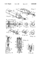
- FIG. 1 is a partially exploded perspective view of a fragmentary portion of a cable transmission system and especially showing a terminator system embodying the principles of the instant invention
- FIG. 2 is an exploded perspective view, partly in section, of a tamper-resistant terminator constructed in accordance with the teachings of the instant invention
- FIG. 3 is a side elevational view of the terminator of claim 2;
- FIG. 4 is an end elevation view taken from the lower end of FIG. 3;
- FIG. 5 illustrates the terminator of the instant invention as it would appear with other components of the terminator system of the instant invention and secured to a selected device in a cable transmission system, portions thereof being broken away for purposes of illustration;
- FIG. 6 is a perspective view of a tool, constructed in accordance with the teachings of the instant invention, especially adapted for installation and removal of a tamper-resistant terminator, the tool being shown in the release position for insertion into a tamper-resistant terminator;
- FIG. 7 is a fragmentary perspective view, generally corresponding to the view of FIG. 6, and showing the tool in the engagement position;
- FIG. 8 is a fragmentary vertical sectional view taken along the line 8--8 of FIG. 7;
- FIG. 9 is a vertical sectional view taken along the line 9--9 of FIG. 8;
- FIG. 10 is an elevational view of the end of the tool seen in FIG. 8;
- FIG. 11 is a fragmentary exploded perspective view of the end of the tool seen in FIG. 8;
- FIG. 12 is a fragmentary perspective view of the end of an alternate embodiment of the tool of the instant invention.
- FIG. 13 is an enlarged end elevational view of the embodiment seen in FIG. 12;
- FIG. 14 is a fragmentary perspective view illustrating the use of the tool for engaging a tamper-resistant terminal with a device in a cable transmission system
- FIG. 15 is an enlarged vertical sectional view taken along the line 15--15 of FIG. 14;
- FIG. 16 is an enlarged fragmentary portion of the illustration of FIG. 15 and showing the tool thereof in the engagement position for rotating the tamper-resistant terminal;
- FIG. 17 is a view generally corresponding to the illustration of FIG. 2 and illustrating an alternate embodiment thereof.
- FIG. 18 is a vertical sectional view taken along the longitudinal axis of the assembled embodiment seen in FIG. 17 and further illustrating an alternate embodiment of a seal especially adapted for sealing the engagement between the terminator and a terminal of a device.
- FIG. 1 illustrates a fragmentary portion of a cable transmission system including a device generally designated by the reference character 20 having a plurality of depending terminals 23, each including an attachment element such as generally cylindrical externally threaded member 24.
- a device 20 having a plurality of depending terminals 23, each including an attachment element such as generally cylindrical externally threaded member 24.
- device 20 is suspended from supporting cable 25 and is connected in series with primary coaxial cable 27 which transmits signals from a central antenna throughout the area served by the CATV system.
- a drop line, generally designated by the reference character 28 provides service to each subscriber.
- Each drop line 28 includes a coaxial cable 29 and a mating element or connector 30 which is mechanically and electrically securable to a selected one of the terminals 23.
- LAN local area network
- connection of a device is made with several terminals of a device.
- An unused terminal such as the terminal represented by the reference character 23a, is terminated with a tamper-resistant terminator to prevent unauthorized access to the signal carried by primary cable 27.
- Service to an authorized user is provided through connection of the respective drop line to a selected terminal such as represented by the terminal 23b. Where service has been disconnected, a tamper-resistant terminator is interposed between the terminal and the drop line as seen with reference to the terminal designated 23c.
- a tamper-resistant terminator is interposed between the terminal and the drop line as seen with reference to the terminal designated 23c.
- several individually usable inventive components which taken together comprise a novel and improved system for effecting the several connections with the terminals of the device.
- FIG. 2 illustrates a tamper-resistant terminator, generally designated by the reference character 40, embodying the principles of the instant invention and including a body 42 and a shield 43.
- Body 42 preferably fabricated of a conductive metallic material such as aluminum or brass, includes internally threaded second mating element or first end 44, second end 45, major diameter outer cylindrical surface 47 adjacent end 44 and coaxial minor diameter outer cylindrical surface 48 extending from second end 45.
- Intermediately located bore 49 and counterbore 50 coaxial with the outer cylindrical surfaces 47 and 48 along the first longitudinal axis of rotation represented by the broken line A, house resistor 52 which provides the necessary terminal impedance as will be readily appreciated by those skilled in the art.
- Bore 53 extending inwardly from first end 44, coaxial with the axis A and terminating with shoulder 54, is threaded for detachable securement to the externally threaded cylindrical member 24 of a selected terminal 23.
- Bore 55 coaxial with the longitudinal axis A, extends inwardly from second end 45.
- Bore 55 is defined by an open end 57, inner end 58 and a smooth continuous cylindrical surface 59 extending therebetween.
- the term "continuous” as used herein refers to the absence of slots, grooves or other irregularities which would breach the integrity of the smooth surface.
- Bore 55 functions as a socket for receiving and engaging a rotating tool as will be described presently.
- Gasket 60 sized to be received within bore 53 and having opening 62 to accommodate resistor 52, may be employed if desired to provide a seal between shoulder 54 and the end of the selected terminal 23.
- Shield 43 comprises first member 63 and second member 64.
- First member 63 includes first end 65, second end 67 and outer surface 68.
- Outer surface 68 carries a plurality of radially spaced longitudinally extending ribs 69. Ribs 69 function as a preferred grip receiving means.
- Frusto-conically beveled surface 70 terminates outer surface 68 adjacent end 65. The function of ribs 69 and of surface 70 will become clear as the description ensues.
- First member 63 both ends of which are open, includes bore 72 and counterbore 73 which are coaxial with the axis A.
- Counterbore 73 which extends inwardly from second end 67, terminates with shoulder 74 approximate end 65.
- Counterbore 73 rotatably receives major diameter outer cylindrical surface 47 of body 42.
- First end 44 of body 42 is receivable against shoulder 74.
- Bore 72 functions as an access port for receiving the threaded member 24 of a selected terminal 23 therethrough for engagement with the threaded bore 53 of body 42.
- Second member 64 includes first end 75, second end 77, major diameter outer cylindrical surface 78 adjacent end 75 and minor diameter outer cylindrical surface 79 adjacent end 77.
- An external thread or second attachment element 80 corresponding to the thread carried by attachment element or threaded member 24 of device 20, extends along the terminal portion of surface 79 adjacent end 77.
- second member 64 further includes bore 82 and counterbore 83.
- Counterbore 83 projects inwardly from end 75 and terminates with annular shoulder 84.
- the several elements of second member 64 extend coaxially along the axis A.
- Second member 64 is engageable with counterbore 73 of first member 63.
- surface 78 is sized to be frictionally engaged or press-fitted into counter bore 73.
- Various bonding mediums may also be employed to effect the engagement.
- the first end 75 of second member 64 is inserted into the bore 73 of first member 43 until the annular shoulder 85 intermediate surfaces 78 and 79 is flush with the second end 67 of first member 43.
- Counterbore 83 is sized to rotationally receive the minor diameter cylindrical surface 48 of body 42. Second end 45 of body 42 is receivable against the annular shoulder 84.
- Bore 82 functions as an access port for receiving a rotating tool therethrough for engagement within the socket provided by bore 55 of body 42.
- FIG. 5 wherein there is illustrated a preferred means of terminating an unused terminal as exemplified by the terminal 23a of device 20.
- An annular elastic seal member 87 is first positioned upon the threaded member of the terminal. The internal diameter of member 87 is sized to sealingly embrace the thread.
- shield 43 advances in the direction indicated by the arrowed line B. As the shield 43 moves, frusto-conically beveled surface 70 engages and lifts the initial portion of seal member 87 for sealing engagement about the terminal portion thereof.
- an end cap 88 which is threadedly engageable with the terminal portion of second member 64.
- a second seal member 87 encircling the surface 79, seals the threaded union.
- the second seal member 87 further abuts the end 67 of first member 63 and the annular shoulder 85 of second member 64 to insure, if necessary, a seal between first member 63 and second member 64.
- Ribs 69 serve to enhance stabilizing shield 43 against rotation, either by hand or by the use of a tool such as a pair of pliers, during attachment and removal of the cap or closure 88.
- terminator 40 seal members 87 and cap or closure 88 are illustrated prior to engagement.
- cap or closure 88 may be removed for alternate attachment of a drop line which has been removed from service.
- the second seal member 87 sealingly engages the connector 30 in a manner analogous to cap or closure 88.
- a seal member 87 for the stated purpose between a terminal and a connector. It will be appreciated that a seal member associated with a terminal will alternately accept either a connector or the terminator of the instant invention.
- FIG. 6 illustrates a tool, generally designated by the reference character 90, constructed in accordance with the teachings of the instant invention and especially adapted for installation and removal of the previously described terminator 40.
- the tool is also usable in connection with prior art terminals such as the device distributed by GILBERT ENGINEERING COMPANY, Phoenix, Ariz. under the designation "F" Series Male Terminator, Theft-Proof, Part No. GTP-59.
- tool 90 includes a handle 92 having a first portion 93 and a second or actuating portion 94. The portions are serially aligned that is, the forward end 95 of first portion 93 resides in juxtaposition with the rearward end 97 of second portion 94.
- Shaft 98 drivingly engaged with first portion 93, projects from forward end 95.
- a terminal portion of shaft 98 adjacent fixed end 99 is fitted into bore 100 to extend along a first longitudinal axis of symmetry represented by the broken line C.
- shaft 98 is retained by set screws 102 in accordance with conventional practice.
- shaft 98 may be press-fitted or bonded into bore 100.
- Disc 103 having knurled outer surface 104 is carried at the free end of shaft 98.
- Outer cylindrical surface 104 is coaxial with a second longitudinal axis of symmetry represented by the broken line D which is parallel to and spaced from the first longitudinal axis of symmetry represented by the broken line C. Accordingly, disc 103 is considered to be eccentric to shaft 98.
- Shaft 105 projecting forwardly from the second portion 94 and drivingly engaged therewith, terminates with free end 107 residing in close relationship with disc 103.
- a knurled terminal portion 108 resides adjacent free end 107.
- Bore 109 extending continuously through second portion 94 and shaft 105, is rotatably journalled upon shaft 98.
- Bore 109 coaxial with shaft 98, extends along the first axis represented by the broken line C.
- shaft 105 and knurled terminal portion 108 are coaxial with a second axis represented by the broken line E which is spaced from and parallel to the first axis represented by the broken line C as further seen in FIG. 9.
- the first axis represented by the broken line C, is equidistant from the second axis of symmetry and the second axis of rotation represented by the broken lines designated D and E, respectively.
- the knurled outer cylindrical surface 104 of disc 103 has approximately the same measurement as the outside diameter of the knurled terminal portion 108 of shaft 105. Accordingly, in response to relative rotation between first portion 93 and second or actuating portion 94 of handle 93, disc 103 is movable between a first position, as seen in FIG. 6, in which disc 103 and shaft 105 are substantially concentric; and a second position, as seen in FIGS. 7 and 10, in which disc 103 and knurled terminal portion 108 are eccentric.
- Shaft 98 and disc 103 are readily fabricated in accordance with various well-known procedures considered to be standard in the art.
- a reduced diameter terminal portion 110 terminating with annular shoulder 112 is formed on shaft 98.
- Terminal portion 110 which is concentric with the longitudinal axis of shaft 98, has a length which generally corresponds to the thickness of disc 103.
- Bore 113 is formed through disc 103 along a longitudinal axis which is spaced from the longitudinal axis of outer surface 104 an amount equal to the distance between the previously described axes C and E.
- Various means may be employed for retaining disc 103 upon shaft 98.
- bore 113 may be sized to be press-fitted upon the reduced diameter portion 110.
- bore 113 may be sized to locationally receive reduced diameter portion 110 and thereafter bonded by any well-known technique, such as brazing.
- knurled surface 104 opposes knurled surface 108 for camming engagement with the socket of the terminator. Only the portion of knurled surface 104 which projects from and opposes the knurled surface 108 is required for the engagement.
- FIGS. 12 and 13 illustrate an alternate embodiment of the invention which is believed to provide better engagement. Seen is a disc segment 114 having an arcuate knurled section 115. Segment 114 is secured to shaft 98 as previously described for eccentric movement relative the longitudinal axis of shaft 98. It will also be appreciated that the arcuate section 115 need not be uniformly cylindrical.
- FIG. 14 illustrates the use of tool 90 for engagement and disengagement of terminator 40 with a selected terminal 23 of device 20.
- shaft 105 and disc 103 are telescopingly receivable through bore 72 of shield 43 into bore 55 of body 42.
- Shaft 105 is of sufficient length to place at least a portion of knurled terminal portion 108 within bore 55.
- surfaces 104 and 108 are cammingly urged into driving engagement with bore 55.
- the body portion 42 of terminator 40 is drivingly engaged with tool 90 for installation and removal relative terminal 23 as seen in FIG. 14. After the installation or removal, terminator 40 is released from tool 90 in response to counterrotation of the handle portions 93 and 94.
- FIG. 17 wherein there is seen an alternate embodiment of a terminator, constructed in accordance with the teachings of the instant invention and generally designated by the reference character 120 including shield 43 having first member 63 and second member 64 as previously described.
- Alternate body 122 in general similarity to previously described body 42 includes first end 123, second end 124 major diameter outer cylindrical surface 125 and minor outer diameter cylindrical surface 127.
- the immediate body is modified by annular groove 128 formed in minor diameter outer cylindrical surface 127 for purposes of receiving and retaining annular seal 129 herein illustrated as a conventional commercially available 0-ring.
- Annular seal 129 sealingly engages the surface of groove of 128 and the internal cylindrical surface 130 of shield 43 to prevent the flow of contaminates within shield 43 between the open ends 65 and 77.
- previously end cap 88 and the associated seal 87 may be eliminated if desired.
- FIG. 18 illustrates annular seal 129 as it would appear in sealing engagement with the annular groove 128 carried by body 122 and the concentric cylindrical surface 130 of shield 43.
- seal 132 an alternate embodiment of previously described seal 87 for sealingly engagement between a terminator of the instant invention and a terminal 23 of device 20.
- Seal 132 includes bore 133 extending through seal 132 carries an internal thread which is matingly received by the externally threaded cylindrical member 24 of terminal 23.
- the thread carried by member 24 has a diameter and a pitch of finite measurement.
- seal 132 is fabricated of a resilient material
- the thread within bore 133 has a pitch which corresponds to the pitch of member 24 and a diameter which, in the free state, is smaller than the diameter of member 24.
- seal 132 includes a first surface 134 which is receivable against the device 20 and a second surface 135 which is receivable against the end of the terminator.
Abstract
Description
Claims (8)
Priority Applications (1)
| Application Number | Priority Date | Filing Date | Title |
|---|---|---|---|
| US07/402,895 US5055060A (en) | 1989-06-02 | 1989-09-05 | Tamper-resistant cable terminator system |
Applications Claiming Priority (2)
| Application Number | Priority Date | Filing Date | Title |
|---|---|---|---|
| US36077789A | 1989-06-02 | 1989-06-02 | |
| US07/402,895 US5055060A (en) | 1989-06-02 | 1989-09-05 | Tamper-resistant cable terminator system |
Related Parent Applications (1)
| Application Number | Title | Priority Date | Filing Date |
|---|---|---|---|
| US36077789A Continuation-In-Part | 1989-06-02 | 1989-06-02 |
Publications (1)
| Publication Number | Publication Date |
|---|---|
| US5055060A true US5055060A (en) | 1991-10-08 |
Family
ID=27001016
Family Applications (1)
| Application Number | Title | Priority Date | Filing Date |
|---|---|---|---|
| US07/402,895 Expired - Lifetime US5055060A (en) | 1989-06-02 | 1989-09-05 | Tamper-resistant cable terminator system |
Country Status (1)
| Country | Link |
|---|---|
| US (1) | US5055060A (en) |
Cited By (73)
| Publication number | Priority date | Publication date | Assignee | Title |
|---|---|---|---|---|
| US5273444A (en) * | 1989-06-02 | 1993-12-28 | Gilbert Engineering Co., Inc. | Tamper-resistant cable terminator system |
| WO1994001902A1 (en) * | 1992-07-10 | 1994-01-20 | Raychem Corporation | Coaxial cable connection protection system |
| US5338225A (en) * | 1993-05-27 | 1994-08-16 | Cabel-Con, Inc. | Hexagonal crimp connector |
| US5486120A (en) * | 1992-07-10 | 1996-01-23 | Raychem Corporation | Coaxial cable connection protection system with multiple chambered, flexible-webbed shroud |
| WO1997008778A1 (en) * | 1995-08-25 | 1997-03-06 | John Mezzalingua Assoc., Inc. | Coaxial cable end connector with integral moisture seal |
| US6491546B1 (en) | 2000-03-07 | 2002-12-10 | John Mezzalingua Associates, Inc. | Locking F terminator for coaxial cable systems |
| US6511333B1 (en) * | 2001-10-03 | 2003-01-28 | Chun Te Lee | Signal connector with a resistor-fixing device |
| US20030207441A1 (en) * | 2002-05-01 | 2003-11-06 | Eyster Curt R. | Devices and methods for analyte concentration determination |
| US6674343B2 (en) | 1999-08-24 | 2004-01-06 | Tresness Irrevocable Patent Trust | Electronic filter assembly |
| US20050185503A1 (en) * | 2004-02-19 | 2005-08-25 | J.C. Steele & Sons | Extrusion auger with removable auger segments and removal tool |
| US20050208833A1 (en) * | 2004-03-16 | 2005-09-22 | Emerson Electronic Connector And Components Company, A Delaware Corp. | Locking terminator for CATV apparatus and method |
| US20060160417A1 (en) * | 2005-01-18 | 2006-07-20 | Montena Noah P | Coaxial cable connector assembly |
| US7144271B1 (en) | 2005-02-18 | 2006-12-05 | Corning Gilbert Inc. | Sealed tamper resistant terminator |
| US20080102704A1 (en) * | 2006-10-26 | 2008-05-01 | John Mezzalingua Associates, Inc. | Coax cable port locking terminator device |
| US7488210B1 (en) * | 2008-03-19 | 2009-02-10 | Corning Gilbert Inc. | RF terminator |
| US20100279548A1 (en) * | 2006-10-26 | 2010-11-04 | Noah Montena | CATV Port Terminator With Contact-Enhancing Ground Insert |
| US20110111623A1 (en) * | 2009-11-06 | 2011-05-12 | Donald Andrew Burris | Integrally Conductive Locking Coaxial Connector |
| US8079860B1 (en) | 2010-07-22 | 2011-12-20 | John Mezzalingua Associates, Inc. | Cable connector having threaded locking collet and nut |
| US8147259B1 (en) * | 2010-11-02 | 2012-04-03 | Chun-Te Lee | Fixing device of anti-theft signal connector |
| US8152551B2 (en) | 2010-07-22 | 2012-04-10 | John Mezzalingua Associates, Inc. | Port seizing cable connector nut and assembly |
| US8157589B2 (en) | 2004-11-24 | 2012-04-17 | John Mezzalingua Associates, Inc. | Connector having a conductively coated member and method of use thereof |
| US8167635B1 (en) | 2010-10-18 | 2012-05-01 | John Mezzalingua Associates, Inc. | Dielectric sealing member and method of use thereof |
| US8167636B1 (en) | 2010-10-15 | 2012-05-01 | John Mezzalingua Associates, Inc. | Connector having a continuity member |
| US8167646B1 (en) | 2010-10-18 | 2012-05-01 | John Mezzalingua Associates, Inc. | Connector having electrical continuity about an inner dielectric and method of use thereof |
| US8172612B2 (en) | 2005-01-25 | 2012-05-08 | Corning Gilbert Inc. | Electrical connector with grounding member |
| US8192237B2 (en) | 2009-05-22 | 2012-06-05 | John Mezzalingua Associates, Inc. | Coaxial cable connector having electrical continuity member |
| US8231406B2 (en) | 2008-10-29 | 2012-07-31 | Corning Gilbert Inc. | RF terminator with improved electrical circuit |
| US8272893B2 (en) | 2009-11-16 | 2012-09-25 | Corning Gilbert Inc. | Integrally conductive and shielded coaxial cable connector |
| US8287310B2 (en) | 2009-02-24 | 2012-10-16 | Corning Gilbert Inc. | Coaxial connector with dual-grip nut |
| US8313345B2 (en) | 2009-04-02 | 2012-11-20 | John Mezzalingua Associates, Inc. | Coaxial cable continuity connector |
| US8323053B2 (en) | 2010-10-18 | 2012-12-04 | John Mezzalingua Associates, Inc. | Connector having a constant contact nut |
| US8337229B2 (en) | 2010-11-11 | 2012-12-25 | John Mezzalingua Associates, Inc. | Connector having a nut-body continuity element and method of use thereof |
| US8342879B2 (en) | 2011-03-25 | 2013-01-01 | John Mezzalingua Associates, Inc. | Coaxial cable connector |
| US8348697B2 (en) | 2011-04-22 | 2013-01-08 | John Mezzalingua Associates, Inc. | Coaxial cable connector having slotted post member |
| US8366481B2 (en) | 2011-03-30 | 2013-02-05 | John Mezzalingua Associates, Inc. | Continuity maintaining biasing member |
| US8388377B2 (en) | 2011-04-01 | 2013-03-05 | John Mezzalingua Associates, Inc. | Slide actuated coaxial cable connector |
| US8398421B2 (en) | 2011-02-01 | 2013-03-19 | John Mezzalingua Associates, Inc. | Connector having a dielectric seal and method of use thereof |
| US8414322B2 (en) | 2010-12-14 | 2013-04-09 | Ppc Broadband, Inc. | Push-on CATV port terminator |
| US8444445B2 (en) | 2009-05-22 | 2013-05-21 | Ppc Broadband, Inc. | Coaxial cable connector having electrical continuity member |
| US20130133487A1 (en) * | 2011-11-25 | 2013-05-30 | Yang-Ming Hsu | Tool Head Structure |
| US8465322B2 (en) | 2011-03-25 | 2013-06-18 | Ppc Broadband, Inc. | Coaxial cable connector |
| US8469739B2 (en) | 2011-02-08 | 2013-06-25 | Belden Inc. | Cable connector with biasing element |
| US8506325B2 (en) | 2008-09-30 | 2013-08-13 | Belden Inc. | Cable connector having a biasing element |
| US8573996B2 (en) | 2009-05-22 | 2013-11-05 | Ppc Broadband, Inc. | Coaxial cable connector having electrical continuity member |
| US8591244B2 (en) | 2011-07-08 | 2013-11-26 | Ppc Broadband, Inc. | Cable connector |
| US8753147B2 (en) | 2011-06-10 | 2014-06-17 | Ppc Broadband, Inc. | Connector having a coupling member for locking onto a port and maintaining electrical continuity |
| US8888526B2 (en) | 2010-08-10 | 2014-11-18 | Corning Gilbert, Inc. | Coaxial cable connector with radio frequency interference and grounding shield |
| US9017101B2 (en) | 2011-03-30 | 2015-04-28 | Ppc Broadband, Inc. | Continuity maintaining biasing member |
| US9048599B2 (en) | 2013-10-28 | 2015-06-02 | Corning Gilbert Inc. | Coaxial cable connector having a gripping member with a notch and disposed inside a shell |
| US9071019B2 (en) | 2010-10-27 | 2015-06-30 | Corning Gilbert, Inc. | Push-on cable connector with a coupler and retention and release mechanism |
| US9130281B2 (en) | 2013-04-17 | 2015-09-08 | Ppc Broadband, Inc. | Post assembly for coaxial cable connectors |
| US9136654B2 (en) | 2012-01-05 | 2015-09-15 | Corning Gilbert, Inc. | Quick mount connector for a coaxial cable |
| US9147963B2 (en) | 2012-11-29 | 2015-09-29 | Corning Gilbert Inc. | Hardline coaxial connector with a locking ferrule |
| US9147955B2 (en) | 2011-11-02 | 2015-09-29 | Ppc Broadband, Inc. | Continuity providing port |
| US9153911B2 (en) | 2013-02-19 | 2015-10-06 | Corning Gilbert Inc. | Coaxial cable continuity connector |
| US9166348B2 (en) | 2010-04-13 | 2015-10-20 | Corning Gilbert Inc. | Coaxial connector with inhibited ingress and improved grounding |
| US9172154B2 (en) | 2013-03-15 | 2015-10-27 | Corning Gilbert Inc. | Coaxial cable connector with integral RFI protection |
| US9190744B2 (en) | 2011-09-14 | 2015-11-17 | Corning Optical Communications Rf Llc | Coaxial cable connector with radio frequency interference and grounding shield |
| US9203167B2 (en) | 2011-05-26 | 2015-12-01 | Ppc Broadband, Inc. | Coaxial cable connector with conductive seal |
| US9287659B2 (en) | 2012-10-16 | 2016-03-15 | Corning Optical Communications Rf Llc | Coaxial cable connector with integral RFI protection |
| US9407016B2 (en) | 2012-02-22 | 2016-08-02 | Corning Optical Communications Rf Llc | Coaxial cable connector with integral continuity contacting portion |
| US9525220B1 (en) | 2015-11-25 | 2016-12-20 | Corning Optical Communications LLC | Coaxial cable connector |
| US9548557B2 (en) | 2013-06-26 | 2017-01-17 | Corning Optical Communications LLC | Connector assemblies and methods of manufacture |
| US9548572B2 (en) | 2014-11-03 | 2017-01-17 | Corning Optical Communications LLC | Coaxial cable connector having a coupler and a post with a contacting portion and a shoulder |
| US9570845B2 (en) | 2009-05-22 | 2017-02-14 | Ppc Broadband, Inc. | Connector having a continuity member operable in a radial direction |
| US9590287B2 (en) | 2015-02-20 | 2017-03-07 | Corning Optical Communications Rf Llc | Surge protected coaxial termination |
| US9711917B2 (en) | 2011-05-26 | 2017-07-18 | Ppc Broadband, Inc. | Band spring continuity member for coaxial cable connector |
| US9762008B2 (en) | 2013-05-20 | 2017-09-12 | Corning Optical Communications Rf Llc | Coaxial cable connector with integral RFI protection |
| US9859631B2 (en) | 2011-09-15 | 2018-01-02 | Corning Optical Communications Rf Llc | Coaxial cable connector with integral radio frequency interference and grounding shield |
| US10033122B2 (en) | 2015-02-20 | 2018-07-24 | Corning Optical Communications Rf Llc | Cable or conduit connector with jacket retention feature |
| US10211547B2 (en) | 2015-09-03 | 2019-02-19 | Corning Optical Communications Rf Llc | Coaxial cable connector |
| US10290958B2 (en) | 2013-04-29 | 2019-05-14 | Corning Optical Communications Rf Llc | Coaxial cable connector with integral RFI protection and biasing ring |
| US11152726B2 (en) * | 2017-06-06 | 2021-10-19 | Sony Semiconductor Solutions Corporation | Connector device and connector system |
Citations (9)
| Publication number | Priority date | Publication date | Assignee | Title |
|---|---|---|---|---|
| US785162A (en) * | 1904-04-28 | 1905-03-21 | Emanuel Freytag | Internal pipe-wrench. |
| US2955497A (en) * | 1958-11-12 | 1960-10-11 | Izzo Albert | Internal pipe wrench |
| US3001169A (en) * | 1956-03-29 | 1961-09-19 | Isaac S Blonder | Transmission-line connector |
| US3845454A (en) * | 1972-10-20 | 1974-10-29 | Gilbert Engineering Co | Tamper-resistant cable terminator |
| US3890028A (en) * | 1973-09-10 | 1975-06-17 | Hi G Inc | Theft proof terminator system for cable TV outlets |
| US4076360A (en) * | 1974-06-21 | 1978-02-28 | The Raymond Lee Organization, Inc. | Safety device for electrical connector device |
| US4168921A (en) * | 1975-10-06 | 1979-09-25 | Lrc Electronics, Inc. | Cable connector or terminator |
| US4469386A (en) * | 1981-09-23 | 1984-09-04 | Viewsonics, Inc. | Tamper-resistant terminator for a female coaxial plug |
| US4824386A (en) * | 1987-10-05 | 1989-04-25 | Souders Roger B | Security connector assembly for mating coaxial connectors |
-
1989
- 1989-09-05 US US07/402,895 patent/US5055060A/en not_active Expired - Lifetime
Patent Citations (9)
| Publication number | Priority date | Publication date | Assignee | Title |
|---|---|---|---|---|
| US785162A (en) * | 1904-04-28 | 1905-03-21 | Emanuel Freytag | Internal pipe-wrench. |
| US3001169A (en) * | 1956-03-29 | 1961-09-19 | Isaac S Blonder | Transmission-line connector |
| US2955497A (en) * | 1958-11-12 | 1960-10-11 | Izzo Albert | Internal pipe wrench |
| US3845454A (en) * | 1972-10-20 | 1974-10-29 | Gilbert Engineering Co | Tamper-resistant cable terminator |
| US3890028A (en) * | 1973-09-10 | 1975-06-17 | Hi G Inc | Theft proof terminator system for cable TV outlets |
| US4076360A (en) * | 1974-06-21 | 1978-02-28 | The Raymond Lee Organization, Inc. | Safety device for electrical connector device |
| US4168921A (en) * | 1975-10-06 | 1979-09-25 | Lrc Electronics, Inc. | Cable connector or terminator |
| US4469386A (en) * | 1981-09-23 | 1984-09-04 | Viewsonics, Inc. | Tamper-resistant terminator for a female coaxial plug |
| US4824386A (en) * | 1987-10-05 | 1989-04-25 | Souders Roger B | Security connector assembly for mating coaxial connectors |
Cited By (141)
| Publication number | Priority date | Publication date | Assignee | Title |
|---|---|---|---|---|
| US5273444A (en) * | 1989-06-02 | 1993-12-28 | Gilbert Engineering Co., Inc. | Tamper-resistant cable terminator system |
| WO1994001902A1 (en) * | 1992-07-10 | 1994-01-20 | Raychem Corporation | Coaxial cable connection protection system |
| US5469613A (en) * | 1992-07-10 | 1995-11-28 | Raychem Corporation | Tool for connecting a coaxial cable terminus to a connection jack |
| US5486120A (en) * | 1992-07-10 | 1996-01-23 | Raychem Corporation | Coaxial cable connection protection system with multiple chambered, flexible-webbed shroud |
| US5338225A (en) * | 1993-05-27 | 1994-08-16 | Cabel-Con, Inc. | Hexagonal crimp connector |
| US5499934A (en) * | 1993-05-27 | 1996-03-19 | Cabel-Con, Inc. | Hexagonal crimp connector |
| WO1997008778A1 (en) * | 1995-08-25 | 1997-03-06 | John Mezzalingua Assoc., Inc. | Coaxial cable end connector with integral moisture seal |
| US6674343B2 (en) | 1999-08-24 | 2004-01-06 | Tresness Irrevocable Patent Trust | Electronic filter assembly |
| US20050001697A1 (en) * | 1999-08-24 | 2005-01-06 | Gould Jerry M. | Electronic filter assembly |
| US6491546B1 (en) | 2000-03-07 | 2002-12-10 | John Mezzalingua Associates, Inc. | Locking F terminator for coaxial cable systems |
| US6511333B1 (en) * | 2001-10-03 | 2003-01-28 | Chun Te Lee | Signal connector with a resistor-fixing device |
| US20030207441A1 (en) * | 2002-05-01 | 2003-11-06 | Eyster Curt R. | Devices and methods for analyte concentration determination |
| US20050185503A1 (en) * | 2004-02-19 | 2005-08-25 | J.C. Steele & Sons | Extrusion auger with removable auger segments and removal tool |
| US7192178B2 (en) | 2004-02-19 | 2007-03-20 | J. C. Steele & Sons, Inc. | Extrusion auger with removable auger segments and removal tool |
| US7510320B2 (en) | 2004-02-19 | 2009-03-31 | J.C. Steele & Sons, Inc. | Extrusion auger with removable auger segments and removal tool |
| US20070127308A1 (en) * | 2004-02-19 | 2007-06-07 | J.C. Steele & Sons, Inc. | Extrusion Auger With Removable Auger Segments and Removal Tool |
| US20050208833A1 (en) * | 2004-03-16 | 2005-09-22 | Emerson Electronic Connector And Components Company, A Delaware Corp. | Locking terminator for CATV apparatus and method |
| US10038284B2 (en) | 2004-11-24 | 2018-07-31 | Ppc Broadband, Inc. | Connector having a grounding member |
| US10965063B2 (en) | 2004-11-24 | 2021-03-30 | Ppc Broadband, Inc. | Connector having a grounding member |
| US9312611B2 (en) | 2004-11-24 | 2016-04-12 | Ppc Broadband, Inc. | Connector having a conductively coated member and method of use thereof |
| US8157589B2 (en) | 2004-11-24 | 2012-04-17 | John Mezzalingua Associates, Inc. | Connector having a conductively coated member and method of use thereof |
| US10446983B2 (en) | 2004-11-24 | 2019-10-15 | Ppc Broadband, Inc. | Connector having a grounding member |
| US20060160417A1 (en) * | 2005-01-18 | 2006-07-20 | Montena Noah P | Coaxial cable connector assembly |
| US7128605B2 (en) | 2005-01-18 | 2006-10-31 | John Mezzalingua Associates, Inc. | Coaxial cable connector assembly |
| US10756455B2 (en) | 2005-01-25 | 2020-08-25 | Corning Optical Communications Rf Llc | Electrical connector with grounding member |
| US8690603B2 (en) | 2005-01-25 | 2014-04-08 | Corning Gilbert Inc. | Electrical connector with grounding member |
| US8172612B2 (en) | 2005-01-25 | 2012-05-08 | Corning Gilbert Inc. | Electrical connector with grounding member |
| US7144271B1 (en) | 2005-02-18 | 2006-12-05 | Corning Gilbert Inc. | Sealed tamper resistant terminator |
| US20060292927A1 (en) * | 2005-02-18 | 2006-12-28 | Burris Donald A | Sealed tamper resistant terminator |
| US7452239B2 (en) * | 2006-10-26 | 2008-11-18 | John Mezzalingua Associates Inc. | Coax cable port locking terminator device |
| US20080102704A1 (en) * | 2006-10-26 | 2008-05-01 | John Mezzalingua Associates, Inc. | Coax cable port locking terminator device |
| US8062044B2 (en) * | 2006-10-26 | 2011-11-22 | John Mezzalingua Associates, Inc. | CATV port terminator with contact-enhancing ground insert |
| US20100279548A1 (en) * | 2006-10-26 | 2010-11-04 | Noah Montena | CATV Port Terminator With Contact-Enhancing Ground Insert |
| US7488210B1 (en) * | 2008-03-19 | 2009-02-10 | Corning Gilbert Inc. | RF terminator |
| WO2009117121A1 (en) | 2008-03-19 | 2009-09-24 | Corning Gilbert Inc. | Rf terminator |
| US8506325B2 (en) | 2008-09-30 | 2013-08-13 | Belden Inc. | Cable connector having a biasing element |
| US8231406B2 (en) | 2008-10-29 | 2012-07-31 | Corning Gilbert Inc. | RF terminator with improved electrical circuit |
| US8287310B2 (en) | 2009-02-24 | 2012-10-16 | Corning Gilbert Inc. | Coaxial connector with dual-grip nut |
| US8313345B2 (en) | 2009-04-02 | 2012-11-20 | John Mezzalingua Associates, Inc. | Coaxial cable continuity connector |
| US8506326B2 (en) | 2009-04-02 | 2013-08-13 | Ppc Broadband, Inc. | Coaxial cable continuity connector |
| US8647136B2 (en) | 2009-05-22 | 2014-02-11 | Ppc Broadband, Inc. | Coaxial cable connector having electrical continuity member |
| US8444445B2 (en) | 2009-05-22 | 2013-05-21 | Ppc Broadband, Inc. | Coaxial cable connector having electrical continuity member |
| US8313353B2 (en) | 2009-05-22 | 2012-11-20 | John Mezzalingua Associates, Inc. | Coaxial cable connector having electrical continuity member |
| US8323060B2 (en) | 2009-05-22 | 2012-12-04 | John Mezzalingua Associates, Inc. | Coaxial cable connector having electrical continuity member |
| US10931068B2 (en) | 2009-05-22 | 2021-02-23 | Ppc Broadband, Inc. | Connector having a grounding member operable in a radial direction |
| US9496661B2 (en) | 2009-05-22 | 2016-11-15 | Ppc Broadband, Inc. | Coaxial cable connector having electrical continuity member |
| US8801448B2 (en) | 2009-05-22 | 2014-08-12 | Ppc Broadband, Inc. | Coaxial cable connector having electrical continuity structure |
| US9660398B2 (en) | 2009-05-22 | 2017-05-23 | Ppc Broadband, Inc. | Coaxial cable connector having electrical continuity member |
| US9570845B2 (en) | 2009-05-22 | 2017-02-14 | Ppc Broadband, Inc. | Connector having a continuity member operable in a radial direction |
| US10862251B2 (en) | 2009-05-22 | 2020-12-08 | Ppc Broadband, Inc. | Coaxial cable connector having an electrical grounding portion |
| US8597041B2 (en) | 2009-05-22 | 2013-12-03 | Ppc Broadband, Inc. | Coaxial cable connector having electrical continuity member |
| US8287320B2 (en) | 2009-05-22 | 2012-10-16 | John Mezzalingua Associates, Inc. | Coaxial cable connector having electrical continuity member |
| US8573996B2 (en) | 2009-05-22 | 2013-11-05 | Ppc Broadband, Inc. | Coaxial cable connector having electrical continuity member |
| US9419389B2 (en) | 2009-05-22 | 2016-08-16 | Ppc Broadband, Inc. | Coaxial cable connector having electrical continuity member |
| US8562366B2 (en) | 2009-05-22 | 2013-10-22 | Ppc Broadband, Inc. | Coaxial cable connector having electrical continuity member |
| US8192237B2 (en) | 2009-05-22 | 2012-06-05 | John Mezzalingua Associates, Inc. | Coaxial cable connector having electrical continuity member |
| US8517763B2 (en) | 2009-11-06 | 2013-08-27 | Corning Gilbert Inc. | Integrally conductive locking coaxial connector |
| US20110111623A1 (en) * | 2009-11-06 | 2011-05-12 | Donald Andrew Burris | Integrally Conductive Locking Coaxial Connector |
| US8272893B2 (en) | 2009-11-16 | 2012-09-25 | Corning Gilbert Inc. | Integrally conductive and shielded coaxial cable connector |
| US9166348B2 (en) | 2010-04-13 | 2015-10-20 | Corning Gilbert Inc. | Coaxial connector with inhibited ingress and improved grounding |
| US10312629B2 (en) | 2010-04-13 | 2019-06-04 | Corning Optical Communications Rf Llc | Coaxial connector with inhibited ingress and improved grounding |
| US9905959B2 (en) | 2010-04-13 | 2018-02-27 | Corning Optical Communication RF LLC | Coaxial connector with inhibited ingress and improved grounding |
| US8079860B1 (en) | 2010-07-22 | 2011-12-20 | John Mezzalingua Associates, Inc. | Cable connector having threaded locking collet and nut |
| US8152551B2 (en) | 2010-07-22 | 2012-04-10 | John Mezzalingua Associates, Inc. | Port seizing cable connector nut and assembly |
| US8888526B2 (en) | 2010-08-10 | 2014-11-18 | Corning Gilbert, Inc. | Coaxial cable connector with radio frequency interference and grounding shield |
| US8167636B1 (en) | 2010-10-15 | 2012-05-01 | John Mezzalingua Associates, Inc. | Connector having a continuity member |
| US8167635B1 (en) | 2010-10-18 | 2012-05-01 | John Mezzalingua Associates, Inc. | Dielectric sealing member and method of use thereof |
| US8323053B2 (en) | 2010-10-18 | 2012-12-04 | John Mezzalingua Associates, Inc. | Connector having a constant contact nut |
| US8382517B2 (en) | 2010-10-18 | 2013-02-26 | John Mezzalingua Associates, Inc. | Dielectric sealing member and method of use thereof |
| US8167646B1 (en) | 2010-10-18 | 2012-05-01 | John Mezzalingua Associates, Inc. | Connector having electrical continuity about an inner dielectric and method of use thereof |
| US9071019B2 (en) | 2010-10-27 | 2015-06-30 | Corning Gilbert, Inc. | Push-on cable connector with a coupler and retention and release mechanism |
| US8147259B1 (en) * | 2010-11-02 | 2012-04-03 | Chun-Te Lee | Fixing device of anti-theft signal connector |
| US8550835B2 (en) | 2010-11-11 | 2013-10-08 | Ppc Broadband, Inc. | Connector having a nut-body continuity element and method of use thereof |
| US8920182B2 (en) | 2010-11-11 | 2014-12-30 | Ppc Broadband, Inc. | Connector having a coupler-body continuity member |
| US8337229B2 (en) | 2010-11-11 | 2012-12-25 | John Mezzalingua Associates, Inc. | Connector having a nut-body continuity element and method of use thereof |
| US8529279B2 (en) | 2010-11-11 | 2013-09-10 | Ppc Broadband, Inc. | Connector having a nut-body continuity element and method of use thereof |
| US8858251B2 (en) | 2010-11-11 | 2014-10-14 | Ppc Broadband, Inc. | Connector having a coupler-body continuity member |
| US8920192B2 (en) | 2010-11-11 | 2014-12-30 | Ppc Broadband, Inc. | Connector having a coupler-body continuity member |
| US8915754B2 (en) | 2010-11-11 | 2014-12-23 | Ppc Broadband, Inc. | Connector having a coupler-body continuity member |
| US10686264B2 (en) | 2010-11-11 | 2020-06-16 | Ppc Broadband, Inc. | Coaxial cable connector having a grounding bridge portion |
| US8414322B2 (en) | 2010-12-14 | 2013-04-09 | Ppc Broadband, Inc. | Push-on CATV port terminator |
| US8398421B2 (en) | 2011-02-01 | 2013-03-19 | John Mezzalingua Associates, Inc. | Connector having a dielectric seal and method of use thereof |
| US8469739B2 (en) | 2011-02-08 | 2013-06-25 | Belden Inc. | Cable connector with biasing element |
| US9153917B2 (en) | 2011-03-25 | 2015-10-06 | Ppc Broadband, Inc. | Coaxial cable connector |
| US8342879B2 (en) | 2011-03-25 | 2013-01-01 | John Mezzalingua Associates, Inc. | Coaxial cable connector |
| US8465322B2 (en) | 2011-03-25 | 2013-06-18 | Ppc Broadband, Inc. | Coaxial cable connector |
| US8469740B2 (en) | 2011-03-30 | 2013-06-25 | Ppc Broadband, Inc. | Continuity maintaining biasing member |
| US9660360B2 (en) | 2011-03-30 | 2017-05-23 | Ppc Broadband, Inc. | Connector producing a biasing force |
| US9017101B2 (en) | 2011-03-30 | 2015-04-28 | Ppc Broadband, Inc. | Continuity maintaining biasing member |
| US9608345B2 (en) | 2011-03-30 | 2017-03-28 | Ppc Broadband, Inc. | Continuity maintaining biasing member |
| US9595776B2 (en) | 2011-03-30 | 2017-03-14 | Ppc Broadband, Inc. | Connector producing a biasing force |
| US8366481B2 (en) | 2011-03-30 | 2013-02-05 | John Mezzalingua Associates, Inc. | Continuity maintaining biasing member |
| US11811184B2 (en) | 2011-03-30 | 2023-11-07 | Ppc Broadband, Inc. | Connector producing a biasing force |
| US10186790B2 (en) | 2011-03-30 | 2019-01-22 | Ppc Broadband, Inc. | Connector producing a biasing force |
| US10559898B2 (en) | 2011-03-30 | 2020-02-11 | Ppc Broadband, Inc. | Connector producing a biasing force |
| US8485845B2 (en) | 2011-03-30 | 2013-07-16 | Ppc Broadband, Inc. | Continuity maintaining biasing member |
| US8480430B2 (en) | 2011-03-30 | 2013-07-09 | Ppc Broadband, Inc. | Continuity maintaining biasing member |
| US8480431B2 (en) | 2011-03-30 | 2013-07-09 | Ppc Broadband, Inc. | Continuity maintaining biasing member |
| US8475205B2 (en) | 2011-03-30 | 2013-07-02 | Ppc Broadband, Inc. | Continuity maintaining biasing member |
| US8388377B2 (en) | 2011-04-01 | 2013-03-05 | John Mezzalingua Associates, Inc. | Slide actuated coaxial cable connector |
| US8348697B2 (en) | 2011-04-22 | 2013-01-08 | John Mezzalingua Associates, Inc. | Coaxial cable connector having slotted post member |
| US9203167B2 (en) | 2011-05-26 | 2015-12-01 | Ppc Broadband, Inc. | Coaxial cable connector with conductive seal |
| US11283226B2 (en) | 2011-05-26 | 2022-03-22 | Ppc Broadband, Inc. | Grounding member for coaxial cable connector |
| US9711917B2 (en) | 2011-05-26 | 2017-07-18 | Ppc Broadband, Inc. | Band spring continuity member for coaxial cable connector |
| US10707629B2 (en) | 2011-05-26 | 2020-07-07 | Ppc Broadband, Inc. | Grounding member for coaxial cable connector |
| US8753147B2 (en) | 2011-06-10 | 2014-06-17 | Ppc Broadband, Inc. | Connector having a coupling member for locking onto a port and maintaining electrical continuity |
| US8758050B2 (en) | 2011-06-10 | 2014-06-24 | Hiscock & Barclay LLP | Connector having a coupling member for locking onto a port and maintaining electrical continuity |
| US8591244B2 (en) | 2011-07-08 | 2013-11-26 | Ppc Broadband, Inc. | Cable connector |
| US9190744B2 (en) | 2011-09-14 | 2015-11-17 | Corning Optical Communications Rf Llc | Coaxial cable connector with radio frequency interference and grounding shield |
| US9859631B2 (en) | 2011-09-15 | 2018-01-02 | Corning Optical Communications Rf Llc | Coaxial cable connector with integral radio frequency interference and grounding shield |
| US9537232B2 (en) | 2011-11-02 | 2017-01-03 | Ppc Broadband, Inc. | Continuity providing port |
| US11233362B2 (en) | 2011-11-02 | 2022-01-25 | Ppc Broadband, Inc. | Devices for biasingly maintaining a port ground path |
| US9147955B2 (en) | 2011-11-02 | 2015-09-29 | Ppc Broadband, Inc. | Continuity providing port |
| US10700475B2 (en) | 2011-11-02 | 2020-06-30 | Ppc Broadband, Inc. | Devices for biasingly maintaining a port ground path |
| US10116099B2 (en) | 2011-11-02 | 2018-10-30 | Ppc Broadband, Inc. | Devices for biasingly maintaining a port ground path |
| US20130133487A1 (en) * | 2011-11-25 | 2013-05-30 | Yang-Ming Hsu | Tool Head Structure |
| US9136654B2 (en) | 2012-01-05 | 2015-09-15 | Corning Gilbert, Inc. | Quick mount connector for a coaxial cable |
| US9768565B2 (en) | 2012-01-05 | 2017-09-19 | Corning Optical Communications Rf Llc | Quick mount connector for a coaxial cable |
| US9484645B2 (en) | 2012-01-05 | 2016-11-01 | Corning Optical Communications Rf Llc | Quick mount connector for a coaxial cable |
| US9407016B2 (en) | 2012-02-22 | 2016-08-02 | Corning Optical Communications Rf Llc | Coaxial cable connector with integral continuity contacting portion |
| US9912105B2 (en) | 2012-10-16 | 2018-03-06 | Corning Optical Communications Rf Llc | Coaxial cable connector with integral RFI protection |
| US9722363B2 (en) | 2012-10-16 | 2017-08-01 | Corning Optical Communications Rf Llc | Coaxial cable connector with integral RFI protection |
| US10236636B2 (en) | 2012-10-16 | 2019-03-19 | Corning Optical Communications Rf Llc | Coaxial cable connector with integral RFI protection |
| US9287659B2 (en) | 2012-10-16 | 2016-03-15 | Corning Optical Communications Rf Llc | Coaxial cable connector with integral RFI protection |
| US9147963B2 (en) | 2012-11-29 | 2015-09-29 | Corning Gilbert Inc. | Hardline coaxial connector with a locking ferrule |
| US9153911B2 (en) | 2013-02-19 | 2015-10-06 | Corning Gilbert Inc. | Coaxial cable continuity connector |
| US9172154B2 (en) | 2013-03-15 | 2015-10-27 | Corning Gilbert Inc. | Coaxial cable connector with integral RFI protection |
| US9130281B2 (en) | 2013-04-17 | 2015-09-08 | Ppc Broadband, Inc. | Post assembly for coaxial cable connectors |
| US10290958B2 (en) | 2013-04-29 | 2019-05-14 | Corning Optical Communications Rf Llc | Coaxial cable connector with integral RFI protection and biasing ring |
| US9762008B2 (en) | 2013-05-20 | 2017-09-12 | Corning Optical Communications Rf Llc | Coaxial cable connector with integral RFI protection |
| US10396508B2 (en) | 2013-05-20 | 2019-08-27 | Corning Optical Communications Rf Llc | Coaxial cable connector with integral RFI protection |
| US9548557B2 (en) | 2013-06-26 | 2017-01-17 | Corning Optical Communications LLC | Connector assemblies and methods of manufacture |
| US9048599B2 (en) | 2013-10-28 | 2015-06-02 | Corning Gilbert Inc. | Coaxial cable connector having a gripping member with a notch and disposed inside a shell |
| US9991651B2 (en) | 2014-11-03 | 2018-06-05 | Corning Optical Communications Rf Llc | Coaxial cable connector with post including radially expanding tabs |
| US9548572B2 (en) | 2014-11-03 | 2017-01-17 | Corning Optical Communications LLC | Coaxial cable connector having a coupler and a post with a contacting portion and a shoulder |
| US10033122B2 (en) | 2015-02-20 | 2018-07-24 | Corning Optical Communications Rf Llc | Cable or conduit connector with jacket retention feature |
| US9590287B2 (en) | 2015-02-20 | 2017-03-07 | Corning Optical Communications Rf Llc | Surge protected coaxial termination |
| US10211547B2 (en) | 2015-09-03 | 2019-02-19 | Corning Optical Communications Rf Llc | Coaxial cable connector |
| US9882320B2 (en) | 2015-11-25 | 2018-01-30 | Corning Optical Communications Rf Llc | Coaxial cable connector |
| US9525220B1 (en) | 2015-11-25 | 2016-12-20 | Corning Optical Communications LLC | Coaxial cable connector |
| US11152726B2 (en) * | 2017-06-06 | 2021-10-19 | Sony Semiconductor Solutions Corporation | Connector device and connector system |
Similar Documents
| Publication | Publication Date | Title |
|---|---|---|
| US5055060A (en) | Tamper-resistant cable terminator system | |
| US5179877A (en) | Tamper-resistant cable terminator system | |
| US5273444A (en) | Tamper-resistant cable terminator system | |
| US4203640A (en) | Electrical cable coupler with rotatable protective covers | |
| US3845454A (en) | Tamper-resistant cable terminator | |
| US4469386A (en) | Tamper-resistant terminator for a female coaxial plug | |
| US5525076A (en) | Longitudinally compressible coaxial cable connector | |
| US4824386A (en) | Security connector assembly for mating coaxial connectors | |
| US4168921A (en) | Cable connector or terminator | |
| US4806116A (en) | Combination locking and radio frequency interference shielding security system for a coaxial cable connector | |
| US20050176296A1 (en) | Nut seal assembly for coaxial cable system components | |
| US6491546B1 (en) | Locking F terminator for coaxial cable systems | |
| US5820416A (en) | Multiple contact wet connector | |
| CN100539301C (en) | Connector | |
| US5667405A (en) | Coaxial cable connector for CATV systems | |
| US6146197A (en) | Watertight end connector for coaxial cable | |
| US5024606A (en) | Coaxial cable connector | |
| CA2571472C (en) | Nut seal assembly for coaxial connector | |
| US5007861A (en) | Crimpless coaxial cable connector with pull back cable engagement | |
| US4163594A (en) | Electrical connector | |
| US20070123101A1 (en) | Nut seal assembly for coaxial cable system components | |
| MXPA03004892A (en) | Connector for hard-line coaxial cable. | |
| WO1993024973A1 (en) | Longitudinally compressible coaxial cable connector | |
| EP0428424A3 (en) | Catv environmental f-connector | |
| CA2371239A1 (en) | Universal quick-disconnect coupling and valve |
Legal Events
| Date | Code | Title | Description |
|---|---|---|---|
| AS | Assignment |
Owner name: GILBERT ENGINEERING COMPANY, INC., A CORP. OF ARIZ Free format text: ASSIGNMENT OF ASSIGNORS INTEREST.;ASSIGNORS:DOWN, WILLIAM J.;HAYWARD, ROBERT D.;REEL/FRAME:005155/0786 Effective date: 19890813 |
|
| STCF | Information on status: patent grant |
Free format text: PATENTED CASE |
|
| AS | Assignment |
Owner name: GILBERT ENGINEERING CO., INC., ARIZONA Free format text: CHANGE OF NAME;ASSIGNORS:GILBERT ENGINEERING COMPANY, INC. (A.K.A. GILBERT ENGINEERING CO., INC. );GILBERT ENGINEERING ACQUISITION CO., INC. (MERGED INTO);REEL/FRAME:006402/0560 Effective date: 19921223 |
|
| FEPP | Fee payment procedure |
Free format text: PAT HLDR NO LONGER CLAIMS SMALL ENT STAT AS INDIV INVENTOR (ORIGINAL EVENT CODE: LSM1); ENTITY STATUS OF PATENT OWNER: LARGE ENTITY Free format text: PAYOR NUMBER ASSIGNED (ORIGINAL EVENT CODE: ASPN); ENTITY STATUS OF PATENT OWNER: LARGE ENTITY |
|
| FPAY | Fee payment |
Year of fee payment: 4 |
|
| FPAY | Fee payment |
Year of fee payment: 8 |
|
| FPAY | Fee payment |
Year of fee payment: 12 |